
2 layers27.9 × 16.5 mm

 AalindOg/AVA-Robot-
Built by Aalind Tiwari, with AI-assisted CAD and development.
Ava carrier is an open-source printed circuit board by AalindOg, from the AalindOg/AVA-Robot- repository on GitHub. It is a 2-layer board of 60 × 40 mm with 18 parts on 23 nets, routed with 61 tracks and 0 vias.
Its parts include 5 connectors, 3 ICs, 2 resistors, 2 diodes and 1 switch. It belongs with the ESP32 boards of this library.
A wheeled robot project for Half Life by Hack Club.
Built by Aalind Tiwari, with AI-assisted CAD and development.
Explore the CAD · Download STEP · View STL · Development journal
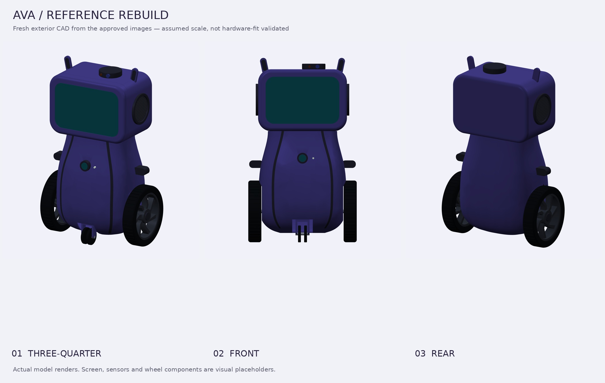
Actual renders of the current model. Not photographs of a fabricated robot.
AVA is a mobile AI companion: a screen for expression and interaction, cameras and microphones for sensing, speakers for responses, and a wheeled body. The longer-term goal is to connect that body to Hermes Agent, with a small controller handling the hardware interface and a computer handling higher-level processing.
This repository brings together three parts of that project: the exterior CAD, the carrier-board design, and the firmware/server prototypes. They are at different stages. The integrated, moving robot is not finished.
The earlier STL attempt did not match the intended robot. Instead of polishing the wrong shape, this version was rebuilt from the original purple robot images and the surviving video views. The older meshes are not imported by the new model.
The design keeps the features that made the reference worth building:
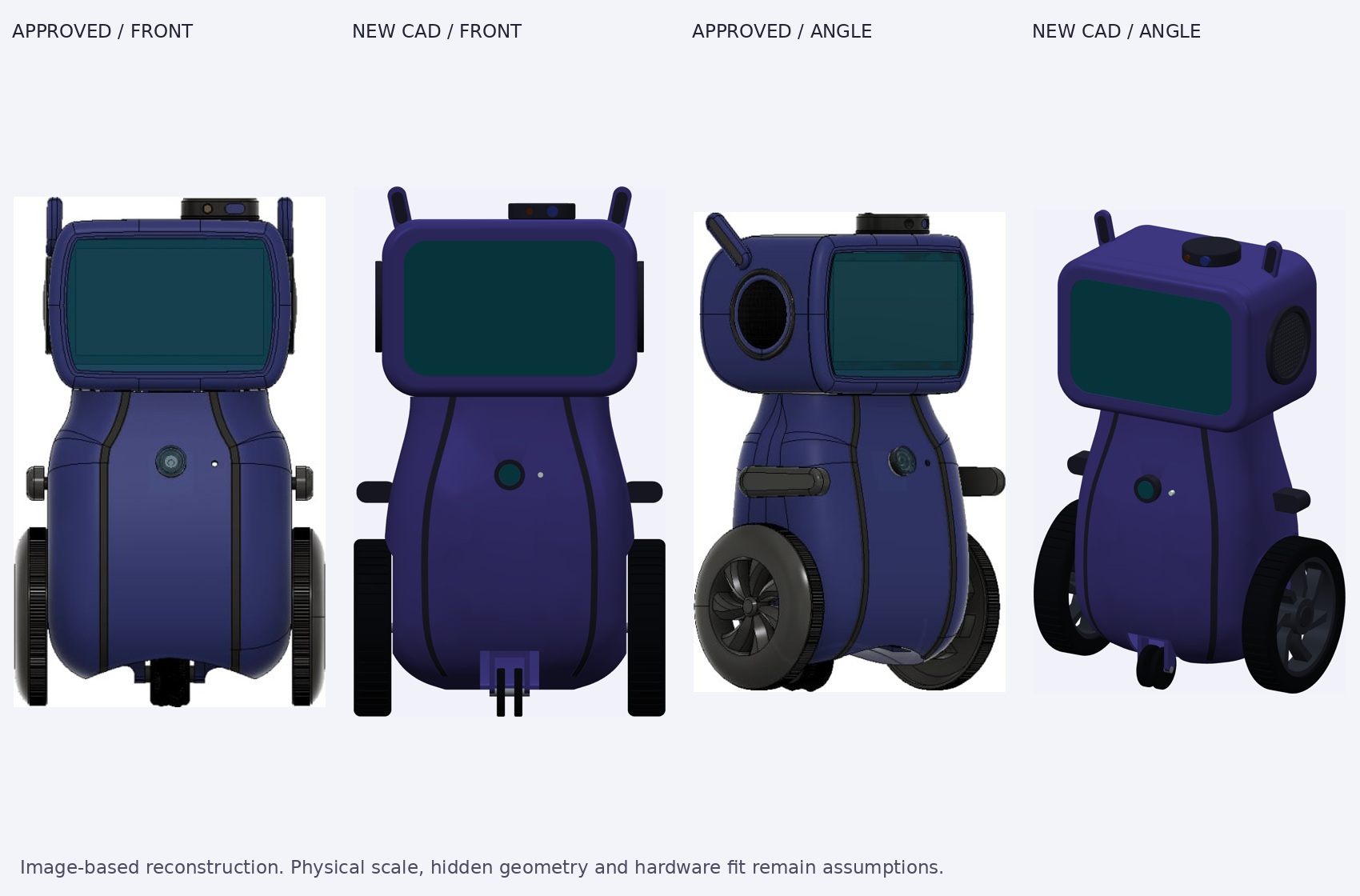
Reference and reconstruction side by side. Fine seams, hidden surfaces and small hardware details are still approximate.
[!IMPORTANT] This is an exterior design prototype, not a print-ready robot kit. The STL files are real geometry exports, but the dimensions are image-based assumptions. Motor mounts, electronics packaging, joints, tolerances and print orientations still need engineering and physical tests. Do not print the complete assembly expecting a working robot.
| File | Use it for |
|---|---|
| Full STEP assembly | Import named, coloured solid components into FreeCAD, Fusion or Onshape. |
| Full STL assembly | Inspect the complete geometry; this is a multi-component assembly, not one fused print. |
| Individual STL components | Inspect or modify separate shell sections, wheels, trim and other components. |
| Coloured GLB model | Open in a compatible 3D viewer. Uses metres and +Y up. |
| CadQuery source | Edit the construction and regenerate the geometry. |
| Design notes | Read the assumptions, interpretation choices and verification scope. |
| Printing status | See what must be resolved before a physical prototype. |
For everything, use GitHub’s Code → Download ZIP, or clone this repository. STEP/STL use millimetres. STEP contains editable solids; the procedural construction lives in the Python source, not a native CAD feature-history tree.
The current CAD export contains 38 component instances. They include visual stand-ins for screens, sensors and axles—not 38 fabrication-ready parts.
| Check | Recorded result | Evidence |
|---|---|---|
| Solid geometry | All 38 component instances valid, with positive volume | Geometry report |
| Component clashes | No intersections above the 0.5 mm³ reporting threshold; no check errors | Pairwise check |
| STL quality | Every individual STL is watertight, consistently wound, finite and positive-volume | Mesh report |
| STEP round trip | Re-imported successfully; solid count and volume comparison passed | Round-trip result |
| Viewer export | GLB re-imported with all 38 components | Viewer check |
| Visual review | Front and angled views compared with the approved images | Comparison sheet |
The assumed exterior envelope is approximately 232 × 147 × 394 mm (width × depth × height). Head width was set to 190 mm as a scaling choice, not a measurement from a physical robot.
These checks establish coherent files. They do not establish strength, stability, printability, electronics fit or successful motion.
The useful outcome is not just a better render: the source, exported solids and validation reports are all here to inspect.
The existing v1 carrier-board design is retained alongside the new CAD. It includes a battery input and power switching, a buck-module connection, a TB6612FNG motor-driver module socket, a XIAO ESP32-S3 Sense socket, motor connectors and an I²C expansion connector.
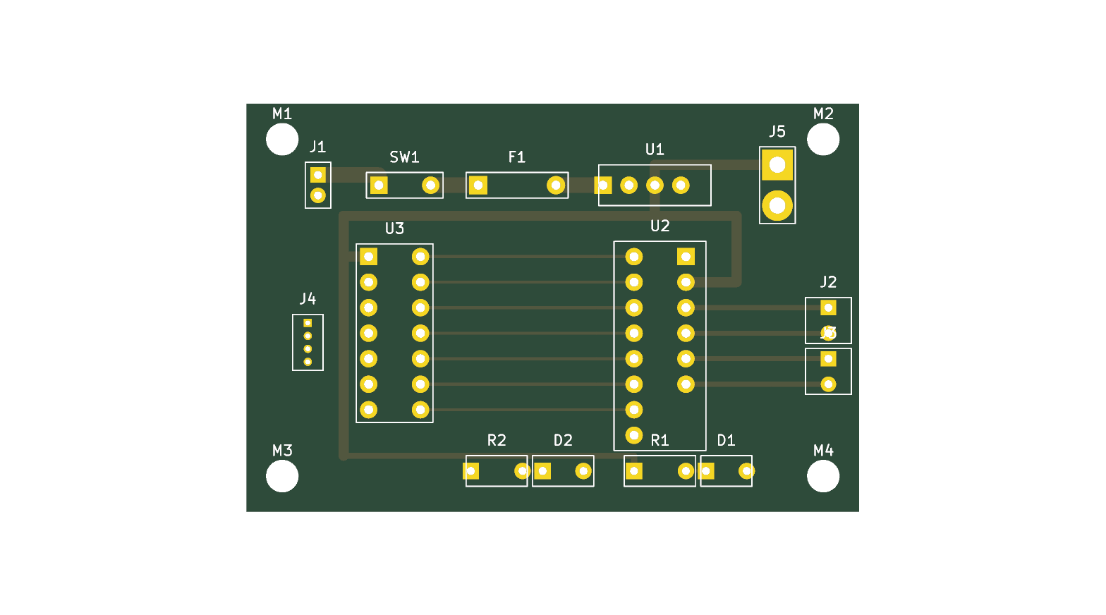
The carrier board and the new enclosure have not been physically integrated or fit-tested. The board files and fabrication exports are design artifacts, not evidence that a board was manufactured or powered successfully. Check component ratings and footprints before ordering or connecting a battery.
The CAD component inventory is separate from the electronics BOM: it lists visual model instances, not parts to purchase.
The repository also retains:
firmware/ — PlatformIO/Arduino sources for the ESP32-S3 sensing and bridge work.server/ — Python audio-receiver, transcription, dashboard and intelligence experiments.The intended division is simple: the controller handles device I/O; the computer handles processing and agent behaviour. These are prototype sources, not proof of a working end-to-end robot. Their runtime and physical integration were not revalidated as part of this CAD update.
Tested with Python 3.12 and CadQuery 2.8.0. From the repository root on Linux/macOS:
cd cad/reference-rebuild
python3 -m venv .venv
.venv/bin/python -m pip install -r requirements.txt

# Generate parts, assembly and geometry checks
.venv/bin/python cad/build_robot.py

# Check all meshes, re-import STEP and export GLB
.venv/bin/python cad/validate_meshes.py

# Render the actual exported geometry and compare with references
.venv/bin/python cad/render_robot.py
.venv/bin/python cad/compare.py
The model is editable procedural CAD, not a fully constrained configurator. Major dimensional changes also require checking the inner shell, openings and neighbouring components. Rerun the checks after edits. More details: CAD README.
The development journal and funding tracker are mirrored from Half Life. Those files are managed by the platform; this update leaves them unchanged. The CAD rebuild is documented here and in design notes, rather than inventing hours or modifying past entries.
AI assistance is part of this work. Aalind selected the reference design, rejected the earlier model and directed the rebuild. Ava/Hermes assisted with procedural CAD generation, debugging, validation, rendering and documentation. This repository does not claim the generated work was completed unaided, that it has already been accepted for a particular week, or that the physical robot has been built.
The source images are kept separately in references so readers can distinguish the design references from the new model renders. Provenance notes describe the surviving source copies; their original author/license is not independently established here.
cad/reference-rebuild/
├── cad/                # Build, render, compare, validate and package scripts
├── exports/            # STEP, STL, GLB, inventory and validation reports
│   └── parts/          # Individual component-instance STLs
├── images/             # Current renders and reference comparison
├── references/         # Source reference views, kept distinct from outputs
├── DESIGN-NOTES.md
└── PRINTING.md
hardware/               # Existing carrier schematic, PCB and fabrication exports
firmware/               # Existing microcontroller prototypes
server/                 # Existing Python prototypes
bom.csv                 # Carrier-board parts list
BOM.md                  # Half Life-managed funding tracker
JOURNAL.md # Half Life-managed devlogThe project’s existing MIT declaration applies to its original code and design contributions. Supplied reference images are not being relicensed by this update; their provenance and usage rights should be checked before reuse outside this project.
| Qty | Value | Footprint | References |
|---|---|---|---|
| 4 | M3 | MOUNT_M3 | M1, M2, M3, M4 |
| 1 | 1k | R1_SOCKET | R1 |
| 1 | 1k | R2_SOCKET | R2 |
| 1 | Buck 5V/5A Module | U1_SOCKET | U1 |
| 1 | I2C Expansion | J4_SOCKET | J4 |
| 1 | LED +5V | D1_SOCKET | D1 |
| 1 | LED VBAT | D2_SOCKET | D2 |
| 1 | LiPo 2S In (JST-PH) | J1_SOCKET | J1 |
| 1 | Motor A (JST-PH) | J2_SOCKET | J2 |
| 1 | Motor B (JST-PH) | J3_SOCKET | J3 |
| 1 | Polyfuse 5A | F1_SOCKET | F1 |
| 1 | Power Switch | SW1_SOCKET | SW1 |
| 1 | SBC 5V Feed (JST-VH) | J5_SOCKET | J5 |
| 1 | TB6612FNG Motor Driver | U2_SOCKET | U2 |
| 1 | XIAO ESP32-S3 Sense | U3_SOCKET | U3 |
It measures 60 × 40 mm and has 2 copper layers, 1.6 mm thick.
18 parts. The full list of its parts is on this page, with links to each part's symbol and footprint where PCBKit's library has them.
From the AalindOg/AVA-Robot- repository on GitHub, at the commit this page was made from: the board is hardware/ava-carrier.kicad_pcb and its schematic hardware/ava-carrier.kicad_sch. PCBKit opens the board in the browser, with nothing to install.
Its repository states no licence, so its author keeps all rights: ask AalindOg before reusing the design.

VoronDesign/Voron-Hardware
Cool Hardware designed by the Voron Design group


hackclub/OnBoard
💡 Join 1,000 teenagers and make your first PCB with a $100 grant!

VoronDesign/Voron-Tap
Tap is a nozzle-based z-probe for the V2 and Trident printer designs. The entire toolhead moves to trigger an optical switch. Tap offers many advantages:

Luos-io/luos_engine
Open-source and real-time orchestrator for cyber-physical-systems, to easily design, test and deploy embedded applications and digital twins.


Twotoz/C5VRX
Ultra-minimal, zero-CPU 5.8 GHz analog FPV video receiver using ESP32-C5 Wi-Fi 6 PHY MODEM_DIAG, BitScrambler WBFM demodulation & resistor DAC CVBS