
6 layers168.8 × 105.3 mm
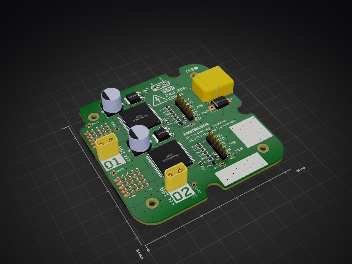
PWM amp is an open-source printed circuit board by YingK8, from the YingK8/FlyingRobotsLinLiweiLab repository on GitHub. It is a 4-layer board of 84 × 84 mm with 53 parts on 44 nets, routed with 315 tracks and 431 vias.
It is built around the NC7SVU04P5X, FDD8447L and XT30UPB-M, with the SMCJ18A and XT60PW-M among its other parts. Its parts include 12 resistors, 8 capacitors, 7 connectors, 4 ICs and 2 transistors. It belongs with the audio and music boards of this library.


| Qty | Value | Footprint | References |
|---|---|---|---|
| 6 | 1k | Resistor_SMD:R_0805_2012Metric_Pad1.20x1.40mm_HandSolder | R1, R5, R6, R7, R8, R9 |
| 6 | 4.7k | Resistor_SMD:R_0805_2012Metric_Pad1.20x1.40mm_HandSolder | R2, R3, R4, R10, R11, R12 |
| 5 | LOGO | LOGO | G***, G***, G***, G***, G*** |
| 4 | 0.1uF | Capacitor_SMD:C_0805_2012Metric_Pad1.18x1.45mm_HandSolder | C1, C2, C7, C8 |
| 4 | MountingHole | MountingHole:MountingHole_3.2mm_M3 | H1, H2, H3, H8 |
| 2 | 100uF | EEH-ZC1H10:CAP_EEH-ZC_10P3X10P3_PAN | C3, C5 |
| 2 | 1uF | Capacitor_SMD:C_0805_2012Metric_Pad1.18x1.45mm_HandSolder | C4, C6 |
| 2 | Conn_01x02_Pin | PinHeader_1x04_P2.54mm_Vertical.kicad_mod:matrix5x5 | J3, J4 |
| 2 | Conn_01x06_Pin | Connector_PinHeader_2.54mm:PinHeader_1x06_P2.54mm_Vertical | J1, J2 |
| 2 | FDD8447L | Package_TO_SOT_SMD:TO-252-2 | Q1, Q2 |
| 2 | NC7SVU04P5X | Package_TO_SOT_SMD:SOT-353_SC-70-5 | U3, U4 |
| 2 | OUTA | TestPoint:TestPoint_Loop_D1.80mm_Drill1.0mm_Beaded | OUT2, OUT2 |
| 2 | OUTB | TestPoint:TestPoint_Loop_D1.80mm_Drill1.0mm_Beaded | OUT1, OUT1 |
| 2 | VNH5019A-E | Package_SO:ST_MultiPowerSO-30 | U1, U2 |
| 2 | XT30UPB-M | XT30UPB-M:AMASS_XT30UPB-M | J5, J10 |
| 1 | GND1 | TestPoint:TestPoint_Loop_D1.80mm_Drill1.0mm_Beaded | PGND |
| 1 | INA1 | TestPoint:TestPoint_Loop_D1.80mm_Drill1.0mm_Beaded | INB1 |
| 1 | INA2 | TestPoint:TestPoint_Loop_D1.80mm_Drill1.0mm_Beaded | INB2 |
| 1 | INB1 | TestPoint:TestPoint_Loop_D1.80mm_Drill1.0mm_Beaded | INA1 |
| 1 | INB2 | TestPoint:TestPoint_Loop_D1.80mm_Drill1.0mm_Beaded | INA2 |
| 1 | SMCJ18A | Diode_SMD:D_SMC-RM10_Universal_Handsoldering | D1 |
| 1 | VM1 | TestPoint:TestPoint_Loop_D1.80mm_Drill1.0mm_Beaded | VM |
| 1 | XT60PW-M | XT60PW-M:AMASS_XT60PW-M | J49 |


AlexAsplund/vanchor-pcb
95×92 mm 2-layer board. Full H-bridge for a 12–24 V brushed trolling motor, controlled by the vanchor-helm board over one straight 8-wire cable. Two build variants share the same PCB:

jrseti/roboclaw-cm4-dc-dish-controller
Satellite dish controller using a ROBOCLAW-2X15A-OEM controlled by a Raspberry Pi CM4 module. Powered by DC battery.
It measures 84 × 84 mm and has 4 copper layers, 1.6 mm thick.
53 parts, built around the NC7SVU04P5X, FDD8447L, XT30UPB-M and SMCJ18A. The full list of its parts is on this page, with links to each part's symbol and footprint where PCBKit's library has them.
From the YingK8/FlyingRobotsLinLiweiLab repository on GitHub, at the commit this page was made from: the board is PCB/PWM_amp/PWM_amp.kicad_pcb and its schematic PCB/Capacitors/Multi_capacitor/Multi_capacitor.kicad_sch. PCBKit opens the board in the browser, with nothing to install.
Its repository states no licence, so its author keeps all rights: ask YingK8 before reusing the design.