2 layers65 × 30 mm
CANFDZeroHAT
generationmake/CANFDZeroHAT
Raspberry Pi HAT with Microchip MCP2518FD CAN FD controller
32 parts27

 Xenii1642/USB-GC224
Meet the new generation of USB-C GameCube Power Board. Now compatible with both 12V and 15V chargers. Two voltages, twice the potential.
USB GC2 is an open-source printed circuit board by Xenii1642, from the Xenii1642/USB-GC2 repository on GitHub, published under the CERN-OHL-S-2.0 licence. It is a 2-layer board of 29.1 × 45.1 mm with 23 parts on 25 nets, routed with 55 tracks and 98 vias.
It is built around the CH224K, TPS621351RGXR and B2B-PH-K-S, with the B2B-XH-A and JS202011JCQN among its other parts. Its parts include 6 resistors, 5 capacitors, 3 connectors, 2 ICs and 2 switches. It belongs with the power boards of this library.


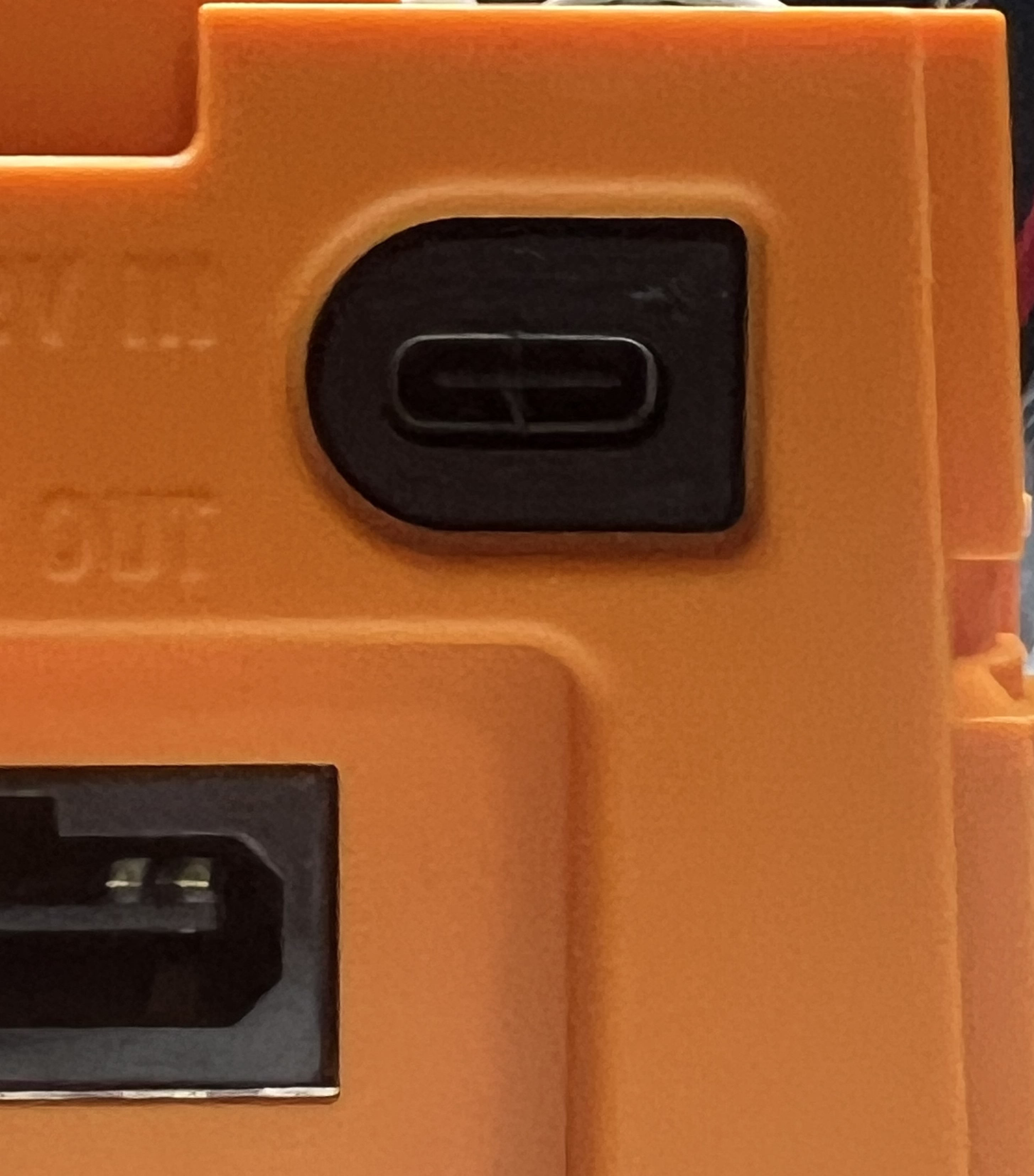
USB-GC2 is new generation GameCube Power Board. It allows powering the console with USB-C Power Delivery. It also contains a switch to select between 12V or 15V input, making it compatible with a variety of Power Delivery chargers. This second revision also integrates securities, which protects the GameCube against voltage spikes. But most importantly, USB-GC2 is now open-source!
Check this Bitbuilt Thread for further informations: BitBuilt Thread
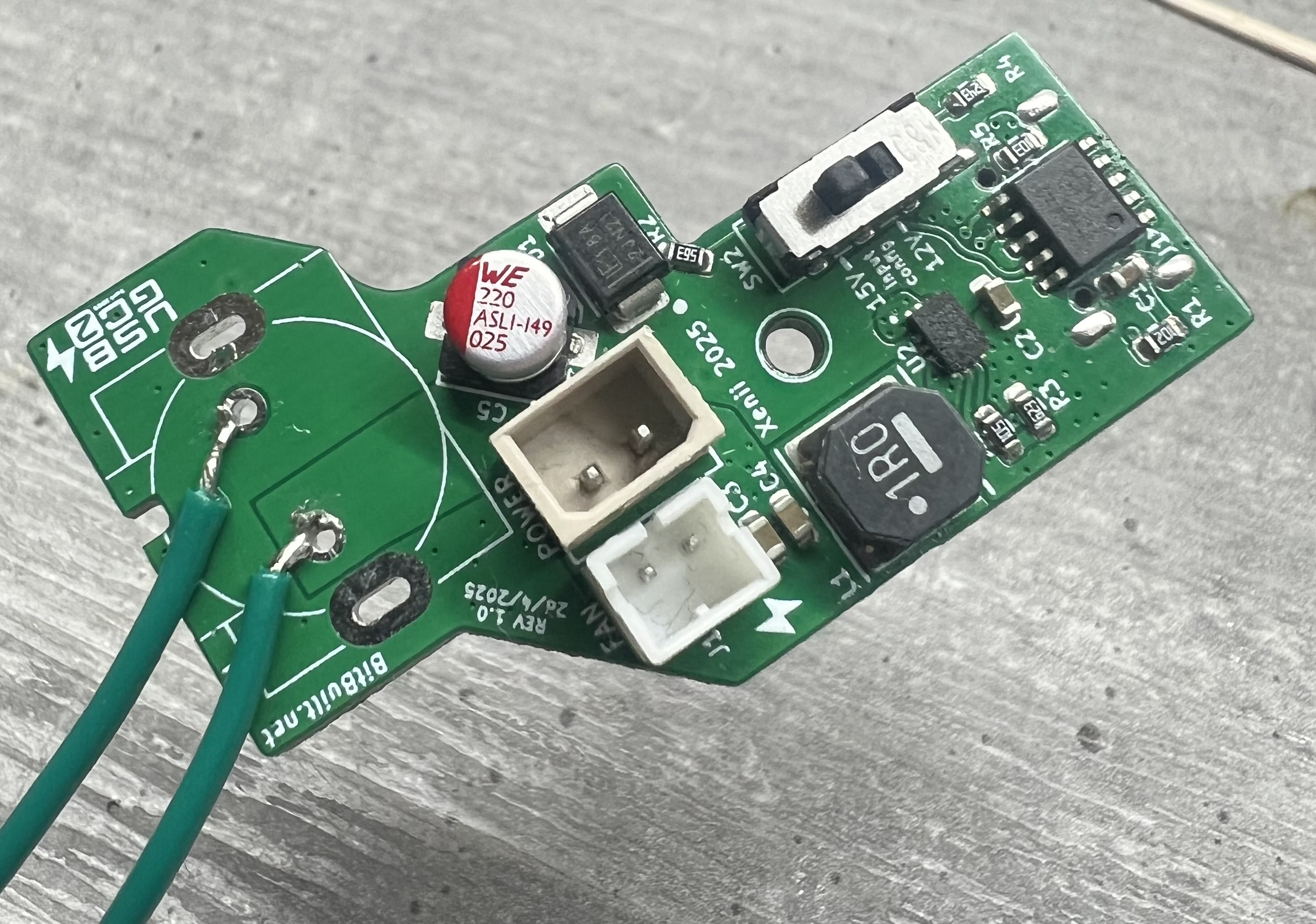
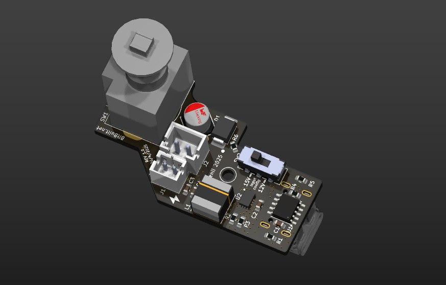
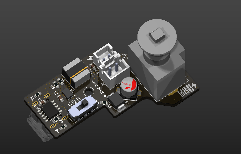
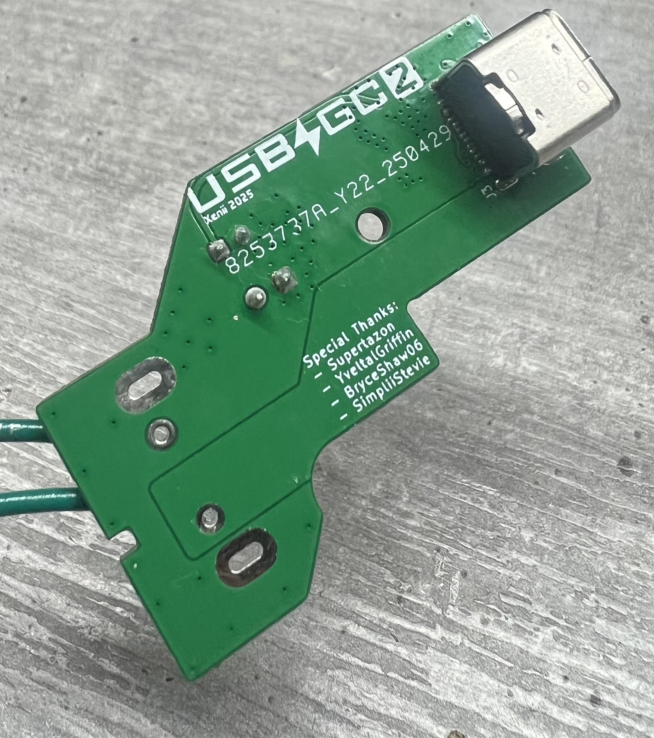
USB-GC2 PCB is available in the PCB section of the repository. Components are all listed in the BOM file.
For ordering, you can simply use the Gerber files. Upload it through your favorite manufacturer. I ordered mine, and personnaly suggest JLCPCB for that board.
For the settings, USB-GC2 doesn't need any. You should however keep the thickness to 1.6mm. You can also change the color, it's up to you!
All the components can be ordered through Digikey or Mouser ⚠️ The links are currently only for Digikey ⚠️
Except for the soldering stuff, you need a compatible USB-C Power Delivery Charger.
The charger needs to be compatible with 12V or 15V. It should also be able to deliver 2.5A of intensity.
Here are two USB-C Power Delivery chargers:
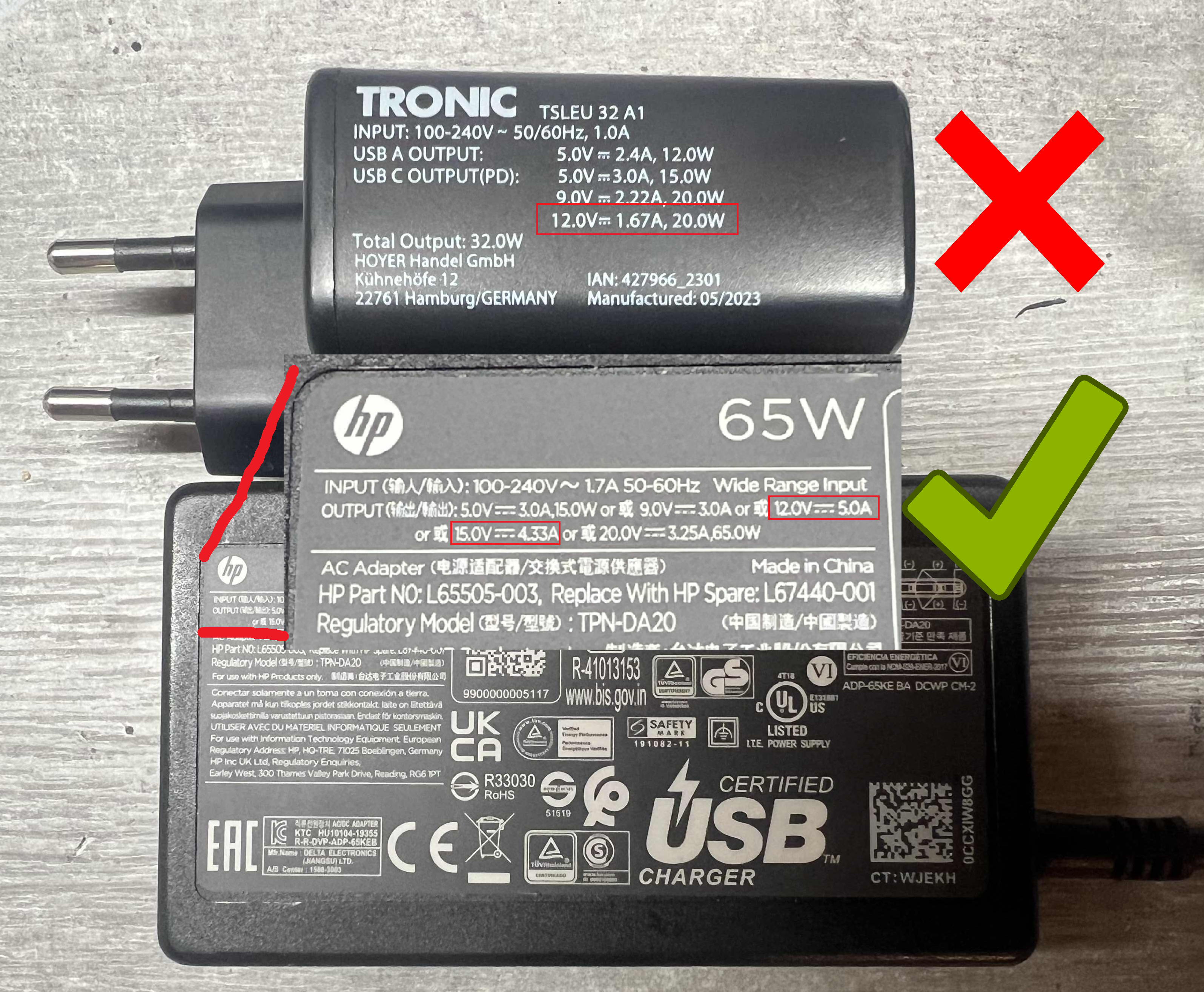
Its voltage is 12V ✅ Its current is 1.67A ❌ ➡️ This charger is not compatible 😭
Voltage is 12V, but it also has 15V ✅ Current is 5A for 12V ✅ Current is 4.33A for 15V ✅ ➡️ This charger is 100% compatible, and you will be able to use it with both input modes! 😊 💡 If that's the case, you should use the 12V input instead of 15V.
USB-GC2 PCB has been designed to be assembled in one time, using a hot plate.
My suggestion is to first apply solder paste (stencil makes life easier, you can find PCB jigs here. Then, place the components using the BOM file
I personally use BI58SN42 solder paste, but all work. Choose the one you're the most confident with 👍
Once the components are placed, I used my mini hot plate to solder everything.
It should then look like this:
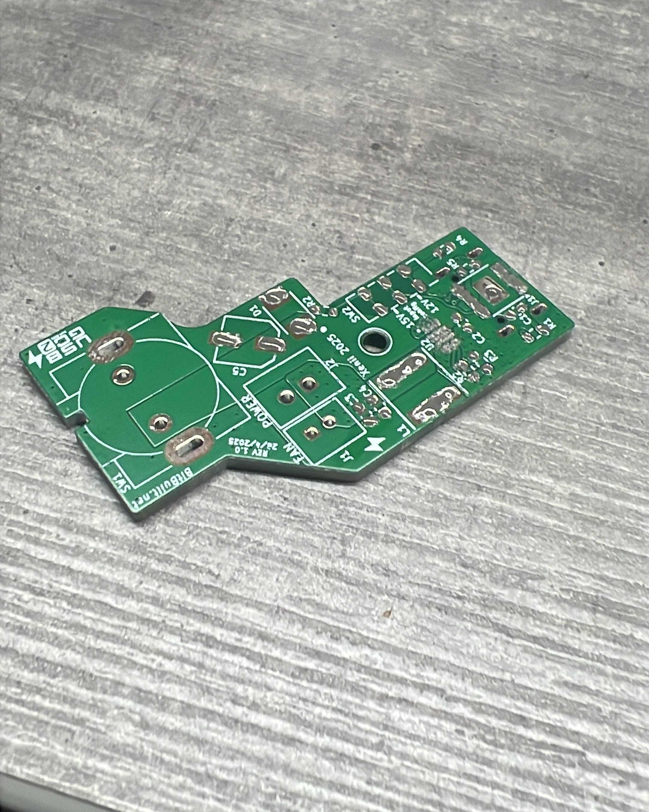
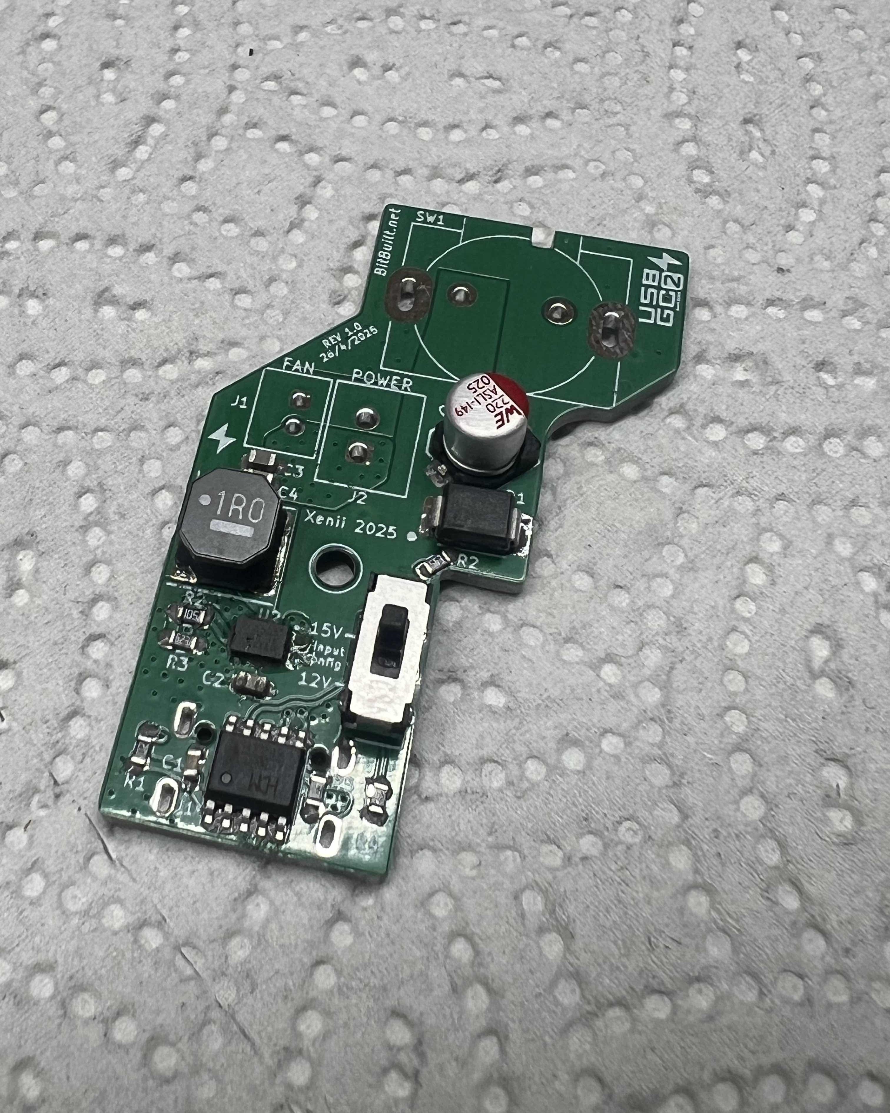
⚠️ Please take note that the original power connector (J2) and the Power Switch (SW1) should / must be took from an original board. ⚠️ 💡The Step Down converter (U2) is the trickest part to solder. I just apply a really little bit of solder paste, and then apply some flux. My recommendation is the SMD291from ChipQuick.
Finally, the last step is to solder the USB-C connector. You can use hot air, but I decided to use my solder iron with the solder paste + plenty of flux. ⚠️ Do not forget to make a good clean of the board to avoid flux / solder paste making shorts between multiples pads. ⚠️
The USB-GC2 only needs one 3D printed cover. It is used to fill the old port and make everything prettier. There is two version of that cover. One with the logo, and one without. If you don't have a 3D printer, you can simply order the cover through JLC3DP.
The USB-GC2 covers are also available on my Printable account: Printables 3D files
Once printed, simply place the cover and push it against the USB-C port. Using the friction fit technology, it should stay in without moving.
To install the new USB-GC2 in your Nintendo GamCube console, you first need to open it up using the 3.5mm security bit. I won't detail the whole dissasembling process here, but you can follow the iFixit guide.
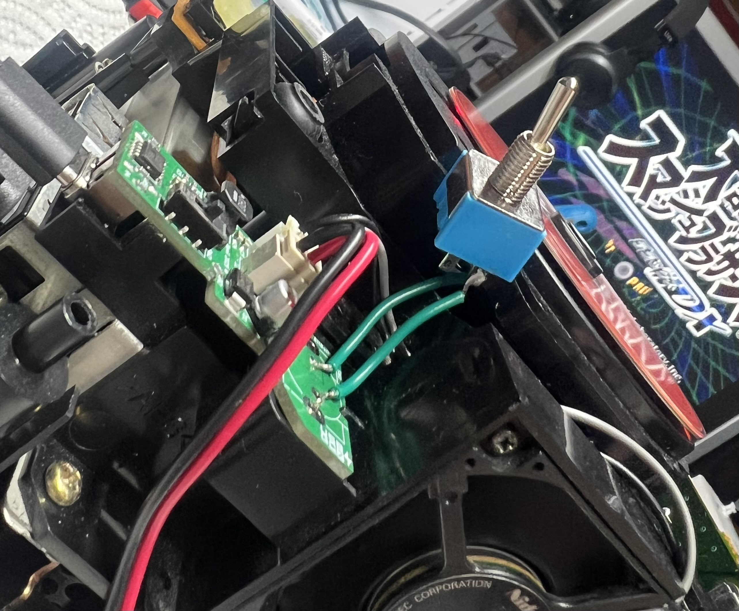
Once the original power board is removed, you can just swap the new USB-GC2 module back in. Do not forget to plug the cables in the correct orientation.
Once everything is installed, simply grab a compatible USB-C Power Delivery Charger.
Plug it carefully and press the switch. You see the GameCube booting on the screen? It means it's working! Congrats!
You can now reassemble your GameCube and enjoy hours of gameplay with the same and universal charger!
The UBS-GC2 is released under the CERN-OHL-S-2.0 license. This license allows you to:
Any modified versions of derivatives must also remain open-source under the same, unmodified license You must also properly credit the original creators when reusing or redistributing these files.
If you see anything wrong with the repository, the USB-GC itself, or else, please let me know. You can also contact me for questions or suggestions! Thanks for your support, and have fun!
| Qty | Value | Footprint | References |
|---|---|---|---|
| 3 | 10uF | Capacitor_SMD:C_0603_1608Metric | C2, C3, C4 |
| 3 | LOGO | LOGO | G***, G***, G*** |
| 1 | 10K | Resistor_SMD:R_0603_1608Metric | R4 |
| 1 | 1K | Resistor_SMD:R_0603_1608Metric | R1 |
| 1 | 1M | Resistor_SMD:R_0603_1608Metric | R2 |
| 1 | 1uF | Capacitor_SMD:C_0603_1608Metric | C1 |
| 1 | 1uH | NRS6045T1R0NMGK:NRS6045T1R0NMGK | L1 |
| 1 | 20V | USB-GC 2:TVS Diode | D1 |
| 1 | 2171800001 | 2171800001:MOLEX_2171800001 | J2 |
| 1 | 22uF | 865080442004:865080442004 | C5 |
| 1 | 24K | Resistor_SMD:R_0603_1608Metric | R5 |
| 1 | 56K | Resistor_SMD:R_0603_1608Metric | R6 |
| 1 | 62K | Resistor_SMD:R_0603_1608Metric | R3 |
| 1 | B2B-PH-K-S | B2B_PH_K_S:JST_B2B-PH-K-S | J1 |
| 1 | B2B-XH-A | B2B_XH_A:JST_B2B-XH-A | J3 |
| 1 | CH224K | CH224K:ESSOP-10 | U1 |
| 1 | JS202011JCQN | JS202011JCQN:SW_JS202011JCQN | SW2 |
| 1 | TPS621351RGXR | TPS621351:TPS621351 | U2 |
| 1 | ~ | GameCube Power Switch:GC-Power-Button | SW2 |
generationmake/CANFDZeroHAT
Raspberry Pi HAT with Microchip MCP2518FD CAN FD controller

davedarko/VectorScopeMusicAddon
A small add-on for the Hackaday Supercon 2023 / Europe 2024 event badge that allows displaying oscilloscope music

rjhsun/moleblink
ATtiny85-based illuminated PCB keychain featuring the Blacker House crest

SpinWearables/SpinWheelHardware
The hardware design files for the SpinWheel.

hannesduske/Fast_SiPM_Photodetector
An open-hardware SiPM photodetector with integrated low-noise amplifier, single-photon resolution, and temperature sensing for active thermal control.

Tinkerbug-Robotics/TinkerRocket
Model rocket flight computer, ground station, iOS app, and simulation

42CrMo4/P00B_UPDI_Programmer
A UPDI Programmer to use the Würth Redfit Skedd Connector and a switch for UPDI and TX of the MCU.

Avinash1286/pendent
AURA: open wearable note-taking device development — PCB, printable case, firmware, Next.js/Convex notes, interactive 3D site and launch film.
It measures 29.1 × 45.1 mm and has 2 copper layers, 1.6 mm thick.
23 parts, built around the CH224K, TPS621351RGXR, B2B-PH-K-S and B2B-XH-A. The full list of its parts is on this page, with links to each part's symbol and footprint where PCBKit's library has them.
From the Xenii1642/USB-GC2 repository on GitHub, at the commit this page was made from: the board is PCB/KiCad 9 Files/USB-GC2.kicad_pcb and its schematic PCB/KiCad 9 Files/USB-GC2.kicad_sch. PCBKit opens the board in the browser, with nothing to install.
Its repository publishes it under the CERN-OHL-S-2.0 licence: you may reuse it on that licence's terms (keep the author's notice, and for a copyleft licence share your changes alike).