
2 layers

 Vihaan6119/RePower
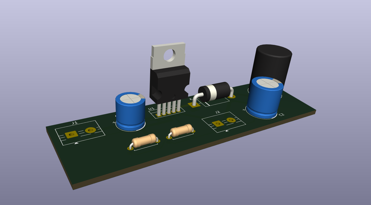
it takes power from a wall adapter via usb-c/dc input and uses a through-hole step down buck regulator (LM2576/LM2596) to convert it to a steady 3.9v dc directly into the speaker's mainboard. it also includes a big 1000uF smoothing capacitor so the speaker can handle heavy bass without rebooting, making the speaker run permanently off wall power
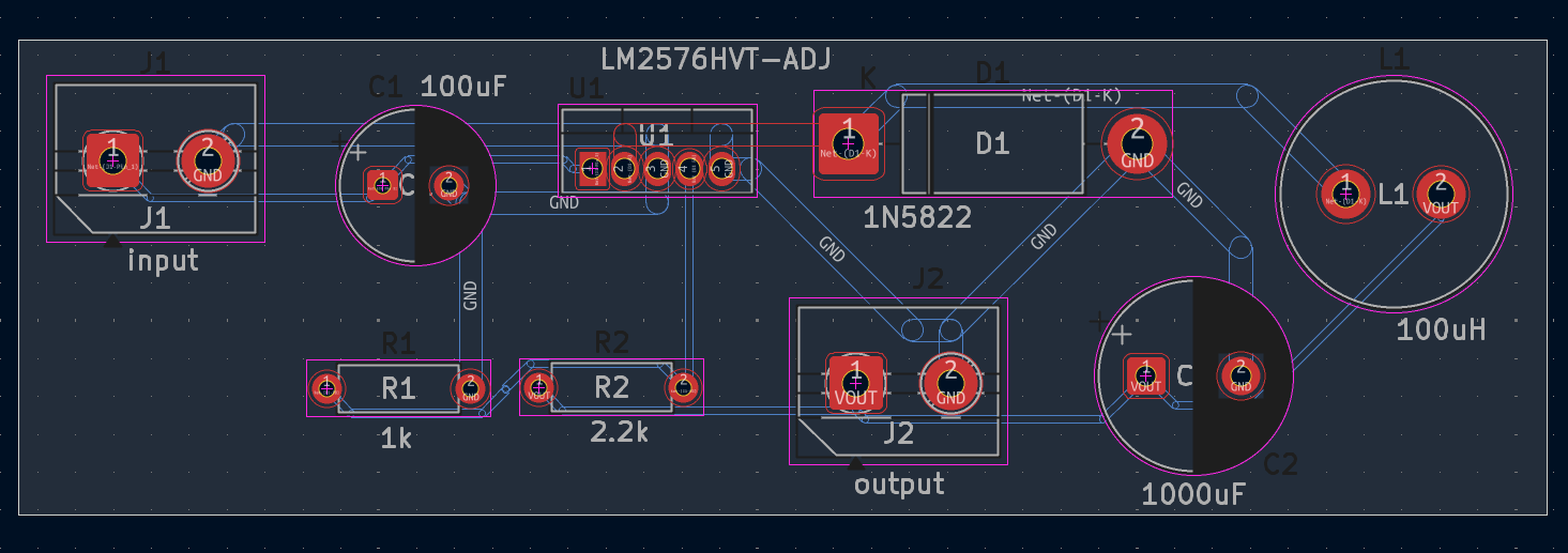
RePower is an open-source printed circuit board by Vihaan6119, from the Vihaan6119/RePower repository on GitHub. It is a 2-layer board of 80.7 × 25 mm with 9 parts on 5 nets, routed with 49 tracks and 0 vias.
It is built around the LM2576HVT-ADJ. Its parts include 2 capacitors, 2 resistors, 2 connectors, 1 IC and 1 diode. It belongs with the power and audio and music boards of this library.
i am made a custom power supply pcb called RePower. it takes power from a wall adapter via usb-c/dc input and uses a through-hole step down buck regulator to convert it to a steady 3.9v dc directly into the speaker's mainboard. it also includes a big 1000uF smoothing capacitor so the speaker can handle heavy bass without rebooting, making the speaker run permanently on wall power
(the speaker i am using is the JBL Charge 2, which is not working (due to battery problem) (what i think) and is dismantled.)
(This case was around 6 months ago)
It all started when I took out the speaker from the shelf, we were going to farmhouse for fun and enjoyment with all of my family members. And we had a very good speaker (The JBL charge 2). So while we were booking, I kept the speaker in charging. For the next 2 hrs it was in charging. But there was no sign of battery increase. So my dad told to keep it in charging overnight. So we keep the speaker in charger overnight, but what happens is that the batter % indicator (the white dots) would be in the same blinking position (like at night the dotted point was at 1 dot or 2 dot and it is blinking then in the morning it is still the same 1 dot or 2 dot blinking). and in the morning if we try to power on the speaker by pressing the power button, the speaker would start, show the blink lights, and the on sound from the speakers would also be there, but after a few seconds, it would power off. so then after getting permission from my dad, i disassembled in the speaker.
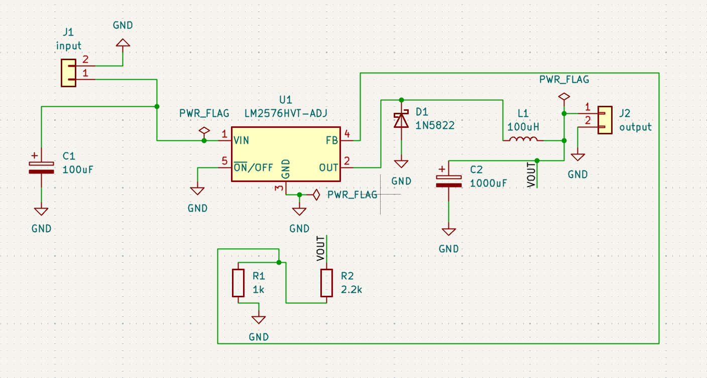
RePower is a through-hole power board that runs my JBL Charge 2 from the wall after its battery died. It takes 9-12V DC from a wall adapter (not accurately measured) and uses an LM2576HVT-ADJ buck regulator to bring it down to about 3.9V (not accurately measured). A 1000uF output capacitor is designed to absorb bass current spikes so the speaker does not reset at higher voltage or higer power.
This is how RePower is planned to work:
A 9-12V DC wall adapter trnasfers the input terminal (J1). C1 smooths the flowing voltage. The LM2576HVT-ADJ (U1) switches that voltage on and off very fast, and the diode (D1) and inductor (L1) smothens the pulses into a steady lower voltage. C2 then filters the output, which goes to the output terminal (J2) and on to the speaker’s battery connector. Two resistors of resistance R1 = 1k and R2 = 2.2k, form a divider that gives parts of the output back to U1’s feedback pin, so the regulator keeps the output at about 1.23 × (1 + 2.2k/1k) = 3.9V (approx. not accurately measured).
RePower/
├── README.md
├── bom.csv
├── JOURNAL.md
├── images/
│   ├── 3d-render.png
│   ├── pcb-layout.png
│   └── schematic.png
└── PCB/
    ├── RePower.kicad_sch
    ├── RePower.kicad_pcb
    ├── RePower.kicad_pro
    ├── RePower.step
└── gerber.zip| Qty | Value | Footprint | References |
|---|---|---|---|
| 1 | 1000uF | Capacitor_THT:CP_Radial_D10.0mm_P5.00mm | C2 |
| 1 | 100uF | Capacitor_THT:CP_Radial_D8.0mm_P3.50mm | C1 |
| 1 | 100uH | Inductor_THT:L_Radial_D12.0mm_P5.00mm_Fastron_11P | L1 |
| 1 | 1N5822 | Diode_THT:D_DO-201AD_P15.24mm_Horizontal | D1 |
| 1 | 1k | Resistor_THT:R_Axial_DIN0207_L6.3mm_D2.5mm_P7.62mm_Horizontal | R1 |
| 1 | 2.2k | Resistor_THT:R_Axial_DIN0207_L6.3mm_D2.5mm_P7.62mm_Horizontal | R2 |
| 1 | LM2576HVT-ADJ | Package_TO_SOT_THT:TO-220-5_Vertical | U1 |
| 1 | input | TerminalBlock:TerminalBlock_MaiXu_MX126-5.0-02P_1x02_P5.00mm | J1 |
| 1 | output | TerminalBlock:TerminalBlock_MaiXu_MX126-5.0-02P_1x02_P5.00mm | J2 |


francesmatthew/BikeLite
This is the schematic and PCB for a buck converter and 555 timer to add flashing LEDs to my bike


saitis-net/sl8500_retrofit_electronics
Kicad projects for the hardware parts

reivax-boucoi/PCB_Kicad
Repo for all my home projects involving PCBs developped with Kicad


It measures 80.7 × 25 mm and has 2 copper layers, 1.6 mm thick.
9 parts, built around the LM2576HVT-ADJ. The full list of its parts is on this page, with links to each part's symbol and footprint where PCBKit's library has them.
From the Vihaan6119/RePower repository on GitHub, at the commit this page was made from: the board is PCB/RePower.kicad_pcb and its schematic PCB/RePower.kicad_sch. PCBKit opens the board in the browser, with nothing to install.
Its repository states no licence, so its author keeps all rights: ask Vihaan6119 before reusing the design.