2 layers116.8 × 30 mm
Type d
google/mozc-devices
Circuit diagrams and firmware source code for Gboard DIY keyboards
14 parts3kApache-2.0

 Vatsal314/Micromouse1
Autonomous maze-solving robot using STM32F411, Flood Fill, VL53L0X ToF sensors, and N20 encoder motors.
Micromouse final is an open-source printed circuit board by Vatsal314, from the Vatsal314/Micromouse repository on GitHub. It is a 2-layer board of 101.6 × 123.8 mm with 14 parts on 53 nets, routed with 242 tracks and 10 vias.
It belongs with the robots and motor control and sensors and measurement boards of this library.
An autonomous, self-navigating maze-solving robot designed to map, compute, and solve a grid using the Flood Fill algorithm. The system features a custom-designed PCB to streamline power and sensing, coupled with real-time sensor feedback over standard serial protocols.
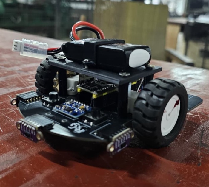
To minimize structural footprint and eliminate complex wiring failure points, a custom multi-layer PCB was fabricated.
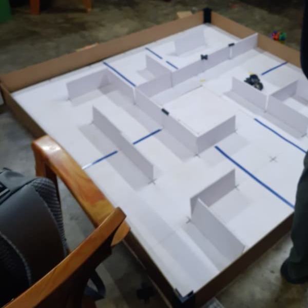
The robot was tested and validated in a physical maze environment configured with the following specifications:
Dimensions and Grid: A modular grid layout featuring distinct pathways, vertical wall dividers, and an enclosed central target zone.
Physical Construction: Built using white foam board panels for the structural walls and a gridded base layer featuring blue alignment markings to delineate cell thresholds.
Core Objective: The robot starts from the outer perimeter and relies on real-time sensory feedback to dynamically map cell paths, track orientation changes, and navigate toward the centralized goal area.
The robot utilizes a dynamic Flood Fill algorithm optimized for real-time maze-mapping, tracking orientation updates, path optimization, and execute routines.
initFloodfill routine populates the arena_map grid using Manhattan distance bounds calculated relative to the target cell coordinate (0, length - 1). Every cell is given an initial cost matrix weight indicating its theoretical steps away from the destination.initWalls function instantiates the initial maze boundary configuration, defaulting the grid's outer boundary elements to closed parameters.detectDist (180 mm), the corresponding coordinate index within the global wall_data matrix is permanently flagged (= 1).facing variable mapping to 0: West, 1: North, 2: East, 3: South). Relative ToF configurations (Left, Front, Right) are translated into absolute compass coordinates to ensure accurate wall updates as the orientation shifts.rearrange_map)rearrange_map routine initiates.Queue structure. The program continuously pops elements from the queue, calculating the minimum accessible neighbor via minimum_value_accessible_neighbors. The cell value is updated dynamically to smallest_neighbor_value + 1, and all unblocked adjacent neighbors are placed into the queue to recursively refresh the local routing map.direction_wrt_bot routine. It converts required compass steps into actual motion commands (moveForward, TurnLeft, TurnRight, Turn180).path_taken. Dead ends or backtracks are parsed by reduceDirections, which processes the path string through a custom stack interface to discard inverse direction pairings (e.g., North-South or East-West cancellations). This converts the discovery track into a clean tracking coordinate sequence saved into short_path.final_run)final_run.steps++). If sequential cells follow a uniform direction, it executes long-distance acceleration (moveForward(steps * steplength * 0.9)) coupled with tuned PD constants (KP_WALL, KD_WALL, KP_YAW), leveraging the N20 encoders for high-speed transit.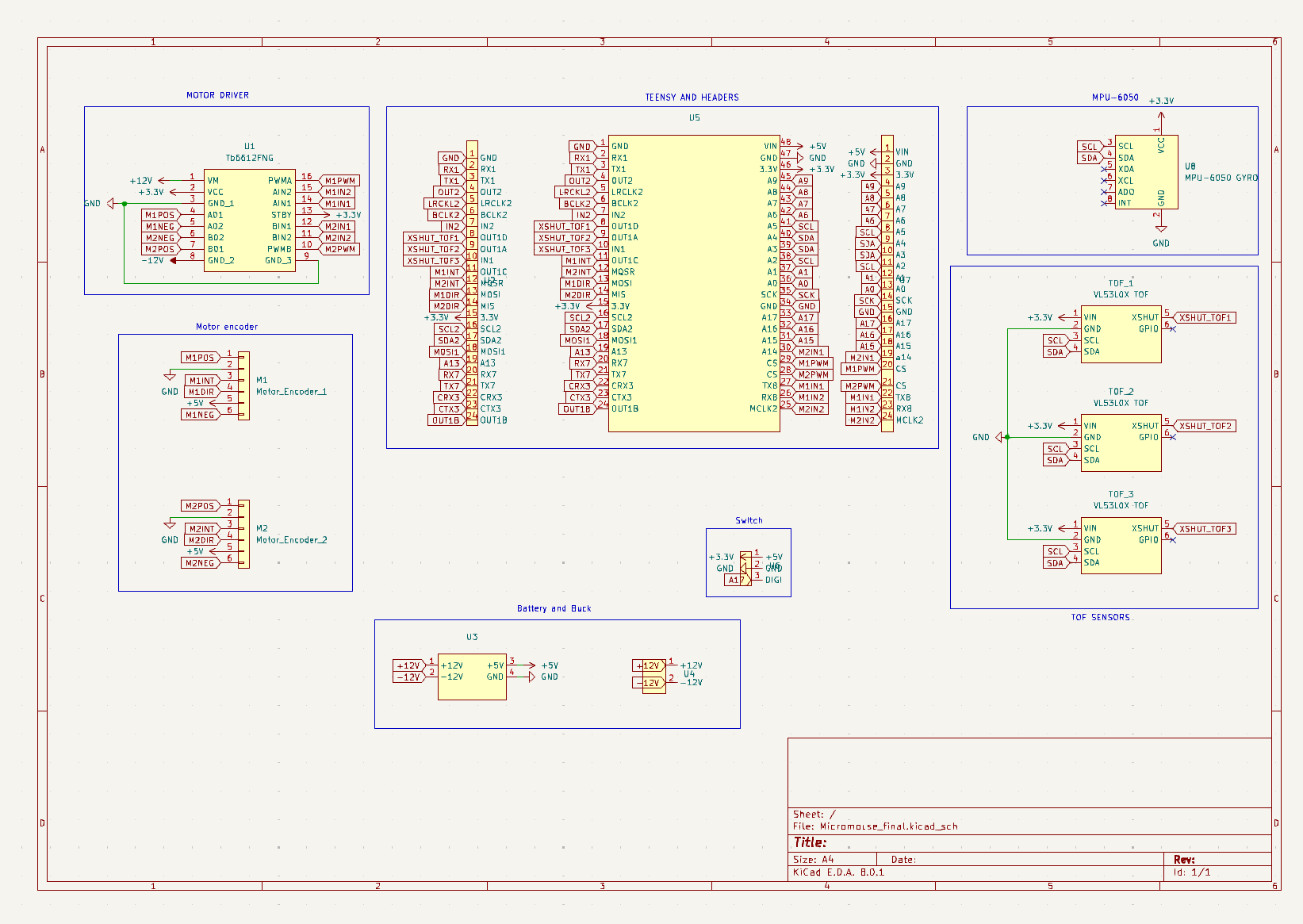
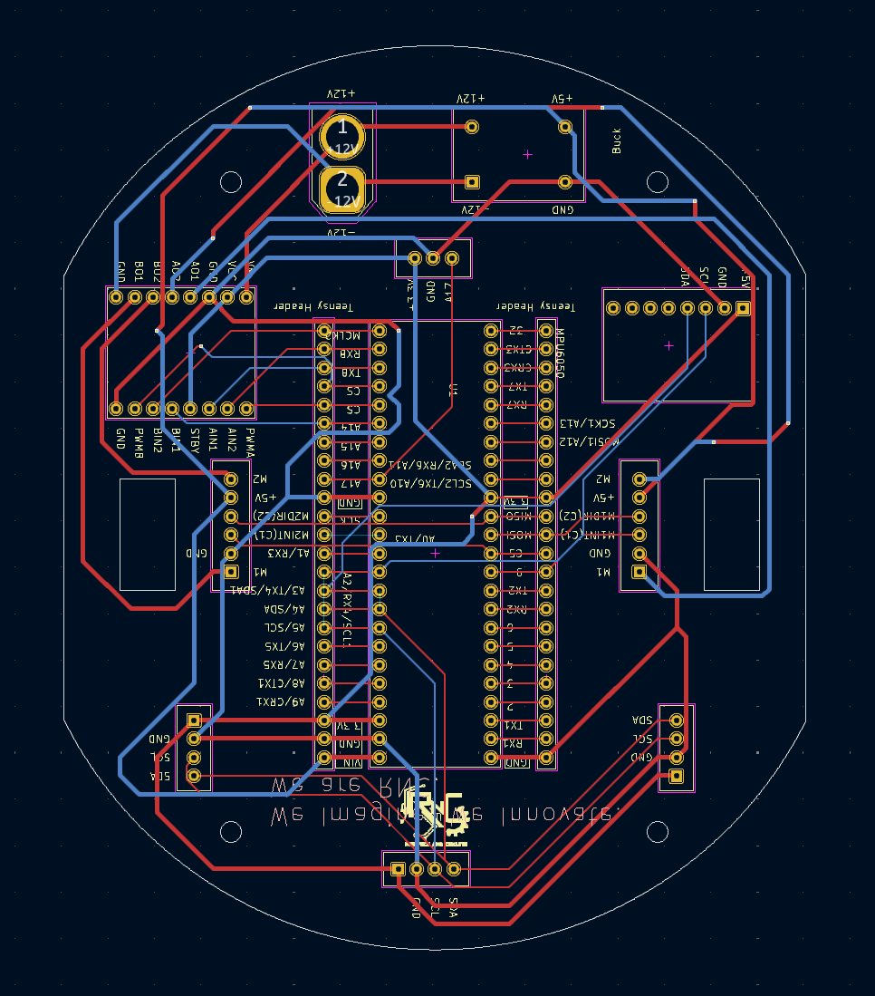
Note on Hardware Evolution: This custom multi-layer PCB was originally architected and routed around a Teensy 4.1 MCU footprint. The subsequent physical implementation and final firmware integration were ported to the STM32F411CEU6 "Black Pill" microcontroller to align with specific processing, layout, and peripheral subsystem constraints.
| Qty | Value | Footprint | References |
|---|---|---|---|
| 3 | VL53L0X TOF | Sensor_TOF:TOF sensor | TOF_1, TOF_2, TOF_3 |
| 2 | ~ | Teensy 4.1:Teensy headers | U2, U7 |
| 1 | LOGO | LOGO | G*** |
| 1 | MPU-6050 GYRO | MPU-6050:MPU6050 | U8 |
| 1 | Motor_Encoder_1 | Motor_N20:Encoder | M1 |
| 1 | Motor_Encoder_2 | Motor_N20:Encoder | M2 |
| 1 | Tb6612FNG | MOTOR_DRIVERS:TB6612FNG | U1 |
| 1 | ~ | Switch_SPDT:SPDT_micromouse | U6 |
| 1 | ~ | Connector_AMASS:AMASS_XT60-F_1x02_P7.20mm_Vertical | U4 |
| 1 | ~ | BUCK:BUCK | U3 |
| 1 | ~ | Teensy_Boards:Teensy_4.1 | U5 |
google/mozc-devices
Circuit diagrams and firmware source code for Gboard DIY keyboards


hackclub/OnBoard
💡 Join 1,000 teenagers and make your first PCB with a $100 grant!


Twotoz/C5VRX
Ultra-minimal, zero-CPU 5.8 GHz analog FPV video receiver using ESP32-C5 Wi-Fi 6 PHY MODEM_DIAG, BitScrambler WBFM demodulation & resistor DAC CVBS


It measures 101.6 × 123.8 mm and has 2 copper layers, 1.6 mm thick.
14 parts. The full list of its parts is on this page, with links to each part's symbol and footprint where PCBKit's library has them.
From the Vatsal314/Micromouse repository on GitHub, at the commit this page was made from: the board is PCB Design Files/Micromouse_final.kicad_pcb and its schematic PCB Design Files/Micromouse_final.kicad_sch. PCBKit opens the board in the browser, with nothing to install.
Its repository states no licence, so its author keeps all rights: ask Vatsal314 before reusing the design.