Skip to the content
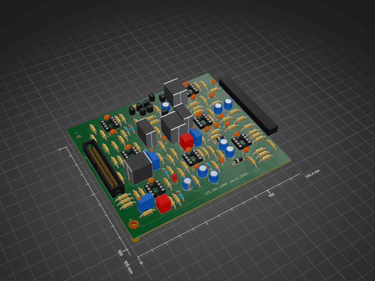
2 layers128.4 × 105 mmCompressor with pcb, the printed circuit board in 3D

Compressor with pcb

UTS-500-Series/Compressor

A 35 × 110 mm board that sits flat behind the faceplate and carries everything on the panel: the five pots, the four toggles, and both LED meters with their two LM3914 drivers.

Size
128.4 × 105 mm
Copper layers
2
Thickness
1.6 mm
Parts
137
Nets
94
Pads
382
Tracks, vias
1,025, 155
Pours
4
Routed
Yes
KiCad
KiCad 10.0 (file 20260206)
Created
5 Aug 2026
Updated
21 Oct 2026

Overview

Compressor with pcb is an open-source printed circuit board by UTS-500-Series, from the UTS-500-Series/Compressor repository on GitHub, published under the CERN-OHL-S-2.0 licence. It is a 2-layer board of 128.4 × 105 mm with 137 parts on 94 nets, routed with 1,025 tracks and 155 vias.

It is built around the NE5532, TL072 and BC549C, with the BZX79-C5V1 among its other parts. Its parts include 69 resistors, 36 capacitors, 9 diodes, 9 transistors and 7 ICs.

Main components

4

README

kicad_withpcb/compressor_front/README.md

Compressor front board

A 35 × 110 mm board that sits flat behind the faceplate and carries everything on the panel: the five pots, the four toggles, and both LED meters with their two LM3914 drivers. It joins the main board with a 30-way ribbon from J1 here to J2 on the main board, pin for pin, with the same net names in both schematics.

The parts are the ones drawn in the main schematic. They stay drawn there (excluded from that board and its BOM) so the circuit still reads as one piece.

How it sits

  • The front of the board faces the panel. Pots, toggles, LEDs, the driver ICs and their small parts all go on the front.
  • J1 (a plain 2×15 pin header) and C38 (47 µF, too tall for the front) go on the back.
  • The toggles are Salecom mini toggles from Altronics: S1350 (DPDT) for BYPASS, S1315 (SPDT) for KEY, HPF and LINK. Their body stands 10.4 mm off the board and the Altronics 9 mm pots stand 10.6 mm, so the board sits about 10.6 mm behind the panel, with the pot bodies against the back of the panel and the toggles 0.2 mm short of it.
  • Alps RK09K pots, if you use them instead, are shorter: make up the difference with a nut behind the panel, which may need the longer bushing version.
  • The LEDs need spacers to reach the panel: about 7.8 mm for the 2 mm flat-tops drawn here (10.6 mm gap less the 2.8 mm LED).
  • Each meter is a column of ten LEDs on a 3.0 mm pitch, so the LED bodies are 0.2 mm apart. The LED footprints' courtyards and silkscreen are trimmed to suit (DRC lists them as differing from the library). 3 mm LEDs no longer fit.
  • The pots' 5 mm bushing leaves under 2 mm of thread through a 3.18 mm panel: see panel/README.md on panel thickness. The toggles' 8.9 mm bushing is plenty.
  • The pins of all four toggles come through the back by about 0.8 mm.
  • The main board's front edge is set back 24 mm from the panel to clear this board, the header and the ribbon plug. The board's back face is now about 12.2 mm behind the panel, so check the plug on J1 still clears it, especially with single-way sockets (taller than an IDC plug).

Joining the boards

The boards are joined only by the ribbon; each one is fixed to the faceplate on its own.

  • Ribbon: 30-way, 2.54 mm pitch, with an IDC socket crimped on each end. Main board J2 is a shrouded box header; J1 here is a plain pin header, so it isn't keyed. Put the red stripe on pin 1 at both ends (pin 1 is marked on the back silkscreen). Altronics has no 30-way IDC parts, so bom/altronics.csv lists a plain 2×15 header for J2 as well and a 150 mm socket-to-socket strip of single-way leads (P1023) for the ribbon. It works, but nothing keys it: keep lead 1 on pin 1 at both ends. For a proper IDC ribbon, buy the box header, two sockets and cable from element14.
  • Length: about 150 mm, folded once between the boards. J2 sits roughly 30 mm behind the panel and about 35 mm higher than J1, and the sideways distance depends on where the main board sits in your rack, so lay the boards out and check before crimping.
  • Front board to panel: the nuts on the five pot and four toggle bushings.
  • Main board to panel: an L-bracket from the back of the panel to H1 and H2, the two M3 holes by the main board's front edge (85 mm apart). The front edge is 24 mm behind the panel, so the bracket leg along the board needs to reach that far: 25 × 25 mm aluminium angle, or a short angle with standoffs. H2 is plated and tied to CHASSIS (J1 pin 1), so the bracket also grounds the panel as the faceplate guide asks. Mask the anodise where the bracket touches the panel. The 3D-printed faceplate in panel/print/ has this bracket built in: two ears that H1 and H2 screw to with M3 × 6 screws into captive nuts, and a wall that runs back along the main board to cover its solder side.

Coordinates

The panel outline and every hole are drawn on User.Drawings, with the grid origin on the panel's top-left corner. The board editor's coordinates read the same as the panel drawing, and panel/make_panel.py takes its hole positions from this board.

3D models

Every part has a 3D model, so the 3D viewer and a STEP export (for the Fusion 360 assembly) show both boards complete.

  • Most come from KiCad's own library.
  • The pots use Alps' official RK09K1130 model. It's the maker's file, so it isn't kept in git: run sh tools/get_3d_models.sh once to fetch it into 3dmodels/. The pots use a project copy of the stock RK09K footprint that points at it.
  • The toggles use simple models built to the Altronics drawings by tools/make_toggle_models.py (case, bushing, lever and pins).
  • The main board's edge fingers are copper, not a part, so J1 there has no model.

Check before ordering

  • The toggle footprints follow the drawings on Altronics' S1315 and S1350 pages: pins on 4.70 mm, 1.3 mm holes, the DPDT's two rows 4.83 mm apart. The S1332 (centre off) has the same drawing as the S1315, so it drops into any SPDT position. Check one switch against the footprint before ordering boards.
  • The toggles sit at x = 7.15 and 30.95 mm (panel coordinates), 0.25 mm in from the old sub-miniature positions, so the S1350's 11.4 mm body stays on the board. The pot footprint's courtyard was trimmed to its pads so it doesn't overlap the S1350's.
  • The Altronics 9 mm pots (R19xx) have the RK09K's pin and lug pattern (lugs 8.6 mm apart, pins 7.0 mm behind them), so they use the same footprint. Their drawing doesn't place the shaft relative to the lugs; the RK09K's is 0.5 mm beyond them. Check before cutting the panel.
  • SW3 (HPF) and SW4 (LINK) are single-pole in the schematic and use the SPDT footprint's top and centre pins; the bottom pin is unused.
  • There are no mounting holes: the nine bushing nuts hold the board. Add standoffs if it flexes.

Parts

137
QtyValueFootprintReferences
16100nCapacitor_THT:C_Disc_D5.0mm_W2.5mm_P5.00mmC7, C20, C23, C24, C25, C26, C27, C28, C29, C30, C31, C32, C33, C34, C41, C42
1410kResistor_THT:R_Axial_DIN0207_L6.3mm_D2.5mm_P10.16mm_HorizontalR11, R12, R19, R20, R29, R30, R39, R40, R41, R43, R84, R85, R86, R94
1022kResistor_THT:R_Axial_DIN0207_L6.3mm_D2.5mm_P10.16mm_HorizontalR1, R2, R3, R4, R23, R24, R80, R81, R82, R83
9BC549CPackage_TO_SOT_THT:TO-92_InlineQ1, Q2, Q3, Q4, Q5, Q6, Q7, Q8, Q9
7100RResistor_THT:R_Axial_DIN0207_L6.3mm_D2.5mm_P10.16mm_HorizontalR5, R6, R28, R32, R33, R34, R52
6NE5532Package_DIP:DIP-8_W7.62mm_SocketU1, U2, U3, U5, U6, U7
51N4148Diode_THT:D_DO-35_SOD27_P7.62mm_HorizontalD5, D6, D7, D11, D12
51kResistor_THT:R_Axial_DIN0207_L6.3mm_D2.5mm_P10.16mm_HorizontalR26, R35, R38, R68, R87
4220RResistor_THT:R_Axial_DIN0207_L6.3mm_D2.5mm_P10.16mm_HorizontalR13, R14, R15, R45
3100uCapacitor_THT:CP_Radial_D6.3mm_P2.50mmC6, C16, C17
310uCapacitor_THT:C_Rect_L16.5mm_W11.8mm_P15.00mm_MKTC5, C8, C15
2100pCapacitor_THT:C_Disc_D5.0mm_W2.5mm_P5.00mmC11, C13
210RResistor_THT:R_Axial_DIN0207_L6.3mm_D2.5mm_P10.16mm_HorizontalR50, R51
21N4004Diode_THT:D_DO-41_SOD81_P7.62mm_HorizontalD8, D9
21nCapacitor_THT:C_Disc_D5.0mm_W2.5mm_P5.00mmC3, C4
220kResistor_THT:R_Axial_DIN0207_L6.3mm_D2.5mm_P10.16mm_HorizontalR42, R44
220kPotentiometer_THT:Potentiometer_Bourns_3296W_VerticalRV7, RV8
222uCapacitor_THT:CP_Radial_D6.3mm_P2.50mmC1, C2
22u2Capacitor_THT:C_Rect_L7.2mm_W7.2mm_P5.00mm_FKS2_FKP2_MKS2_MKP2C14, C35
247uCapacitor_THT:CP_Radial_D6.3mm_P2.50mmC19, C21
24k7Resistor_THT:R_Axial_DIN0207_L6.3mm_D2.5mm_P10.16mm_HorizontalR16, R17
24u7Capacitor_THT:C_Rect_L16.5mm_W7.3mm_P15.00mm_MKTC9, C10
25k1Resistor_THT:R_Axial_DIN0207_L6.3mm_D2.5mm_P10.16mm_HorizontalR31, R49
26k8Resistor_THT:R_Axial_DIN0207_L6.3mm_D2.5mm_P10.16mm_HorizontalR21, R22
10RResistor_THT:R_Axial_DIN0207_L6.3mm_D2.5mm_P10.16mm_HorizontalR48
1100kResistor_THT:R_Axial_DIN0207_L6.3mm_D2.5mm_P10.16mm_HorizontalR88
110nCapacitor_THT:C_Disc_D5.0mm_W2.5mm_P5.00mmC18
111kResistor_THT:R_Axial_DIN0207_L6.3mm_D2.5mm_P10.16mm_HorizontalR10
115kResistor_THT:R_Axial_DIN0207_L6.3mm_D2.5mm_P10.16mm_HorizontalR47
118kResistor_THT:R_Axial_DIN0207_L6.3mm_D2.5mm_P10.16mm_HorizontalR93
11k33Resistor_THT:R_Axial_DIN0207_L6.3mm_D2.5mm_P10.16mm_HorizontalR61
11k5Resistor_THT:R_Axial_DIN0207_L6.3mm_D2.5mm_P10.16mm_HorizontalR18
11k8Resistor_THT:R_Axial_DIN0207_L6.3mm_D2.5mm_P10.16mm_HorizontalR53
1220kResistor_THT:R_Axial_DIN0207_L6.3mm_D2.5mm_P10.16mm_HorizontalR74
123k2Resistor_THT:R_Axial_DIN0207_L6.3mm_D2.5mm_P10.16mm_HorizontalR62
124kResistor_THT:R_Axial_DIN0207_L6.3mm_D2.5mm_P10.16mm_HorizontalR60
12kPotentiometer_THT:Potentiometer_Bourns_3296W_VerticalRV1
136kResistor_THT:R_Axial_DIN0207_L6.3mm_D2.5mm_P10.16mm_HorizontalR69
13k9Resistor_THT:R_Axial_DIN0207_L6.3mm_D2.5mm_P10.16mm_HorizontalR77
147RResistor_THT:R_Axial_DIN0207_L6.3mm_D2.5mm_P10.16mm_HorizontalR46
147kResistor_THT:R_Axial_DIN0207_L6.3mm_D2.5mm_P10.16mm_HorizontalR37
14u7Capacitor_THT:CP_Radial_D6.3mm_P2.50mmC22
168kResistor_THT:R_Axial_DIN0207_L6.3mm_D2.5mm_P10.16mm_HorizontalR9
175RResistor_THT:R_Axial_DIN0207_L6.3mm_D2.5mm_P10.16mm_HorizontalR8
182kResistor_THT:R_Axial_DIN0207_L6.3mm_D2.5mm_P10.16mm_HorizontalR36
18k2Resistor_THT:R_Axial_DIN0207_L6.3mm_D2.5mm_P10.16mm_HorizontalR7
1BZX79-C5V1Diode_THT:D_DO-35_SOD27_P7.62mm_HorizontalD10
1Bracket M3MountingHole:MountingHole_3.2mm_M3_PadH2
1Bracket M3MountingHole:MountingHole_3.2mm_M3H1
1EDA 306Cards:EDA_306J1
1FRONT BOARDConnector_IDC:IDC-Header_2x15_P2.54mm_VerticalJ2
1GRLED_THT:LED_D3.0mmLED1
1TL072Package_DIP:DIP-8_W7.62mm_SocketU4

More from UTS-500-Series/Compressor

1
  • 2 layers35 × 110 mmCompressor front, the printed circuit board in 3D

    Compressor front

    UTS-500-Series/Compressor

    A 35 × 110 mm board that sits flat behind the faceplate and carries everything on the panel: the five pots, the four toggles, and both LED meters with their two LM3914 drivers.

    39 partsCERN-OHL-S-2.0

Similar boards

  • 2 layers60.8 × 99.9 mmReSeed, the printed circuit board in 3D

    ReSeed

    SukkoPera/ReSeed

    Sounds from C64 now for Plus/4!

    59 parts15
  • 2 layers63 × 98 mmThermostat, the printed circuit board in 3D

    Thermostat

    sensei-hacker/open-smart-thermostat

    A 24 VAC HVAC thermostat board. A Seeed XIAO RP2040 handles temperature control and switches the HVAC wires through optically isolated triacs. An M5Stack Dial provides the user interface.

    76 partsMIT
  • 2 layers82.6 × 64.8 mmTa101bc, the printed circuit board in 3D

    Ta101bc

    TuchAudio/ta101b

    Discrete Phono preamp

    99 partsMIT
  • 2 layersCjss301, the printed circuit board in 3D

    Cjss301

    zuiko21/minimOS

    Scalable OS for 6502/65816

    81 parts23MIT
  • 2 layers100.5 × 66.5 mmN22 DCAmplifier, the printed circuit board in 3D

    N22 DCAmplifier

    deqit/PhilipsPM2528

    Hardware and software for the Philips PM2528

    81 parts3
  • 2 layers38.1 × 65.4 mmSequencer back pcb, the printed circuit board in 3D

    Sequencer back pcb

    yry-dev/maddie-synths

    My Open Source / Public Eurorack projects

    14 parts1
  • 2 layers165 × 103.8 mmOutput pcb, the printed circuit board in 3D

    Output pcb

    QuinnFreedman/modular

    A collection of free & open source DIY synthesizer module designs for Eurorack

    128 parts116
  • 2 layers80 × 60 mmDigishaper152, the printed circuit board in 3D

    Digishaper152

    jonnor/projects

    Small projects not worthy of dedicated repositories

    61 parts45

Questions

How big is the Compressor with pcb PCB?

It measures 128.4 × 105 mm and has 2 copper layers, 1.6 mm thick.

What parts does the Compressor with pcb use?

137 parts, built around the NE5532, TL072, BC549C and BZX79-C5V1. The full list of its parts is on this page, with links to each part's symbol and footprint where PCBKit's library has them.

Where can I download the Compressor with pcb KiCad files?

From the UTS-500-Series/Compressor repository on GitHub, at the commit this page was made from: the board is kicad_withpcb/compressor_with_pcb/compressor_with_pcb.kicad_pcb and its schematic kicad/UTS Mini Mixing Desk - Compressor.kicad_sch. PCBKit opens the board in the browser, with nothing to install.

Can I use the Compressor with pcb design in my own project?

Its repository publishes it under the CERN-OHL-S-2.0 licence: you may reuse it on that licence's terms (keep the author's notice, and for a copyleft licence share your changes alike).