2 layers85.6 × 54 mm
Ramn
ToyotaInfoTech/RAMN
RAMN (Resistant Automotive Miniature Network), a miniature CAN/CAN-FD testbed of 4 Electronic Control Units.
106 parts285
 ToyotaInfoTech/RAMN285
RAMN (Resistant Automotive Miniature Network), a miniature CAN/CAN-FD testbed of 4 Electronic Control Units.
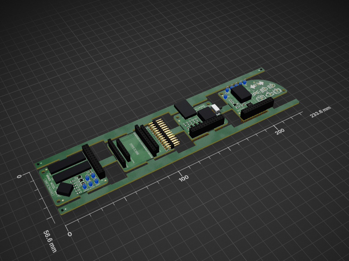
Pods panel is an open-source printed circuit board by ToyotaInfoTech, from the ToyotaInfoTech/RAMN repository on GitHub. It is a 2-layer board of 233.6 × 56.6 mm with 191 parts on 135 nets, routed with 596 tracks and 59 vias.
It is built around the STP08CP05XT, SK14EG13 and SKRHADE010. Its parts include 15 resistors, 8 diodes, 8 connectors, 4 capacitors and 4 switches.


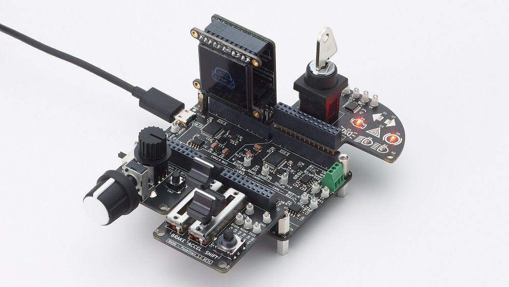
RAMN (Resistant Automotive Miniature Network) is a miniature CAN/CAN-FD testbed of four Electronic Control Units (ECUs) consiting solely of Printed Circuit Boards. The ECUs can be programmed to emulate the same network traffic as PASTA, another project from our team. RAMN is powered over USB and can be recognized as a standard CAN adapter. It can be connected in closed-loop with the autonomous driving simulator CARLA. What happens to the virtual vehicle has an impact on the physical CAN/CAN-FD bus, and vice versa. RAMN can be expanded with many stackable expansions, ranging from external quadSPI memories to Trusted Platform Modules (TPMs).
Please check the Documentation for demonstrations and details.

This project is open-source and RAMN boards can be fabricated by most PCB assembly prototyping services.
We have setup 're-orders' at PCBWay. Please see the docs 'PCB Ordering' for more details. You can also request a prototype from any PCB manufacturer, using the Gerber files and BOM in the Hardware folder.
Feel free to contact us if you need assistance to fabricate or sell RAMN boards.
Because component availability is subject to change, we are periodically updating the hardware. The original RAMN hardware data is available in misc/RAMN_V1_reference_PCB.zip, and is recommended for academic purposes.
Contains design files, from KiCAD project files to Gerber files and BOM.
Contains various scripts to interact with the ECUs:
Contains firmware source code for RAMN's ECUs.
Please check the LICENSE.md file for more details.
Feel free to contact us if you have questions. Videos available here.
Copyright (c) 2026 TOYOTA MOTOR CORPORATION. ALL RIGHTS RESERVED.
| Qty | Value | Footprint | References |
|---|---|---|---|
| 101 | NPTH | NPTH | KiKit_MB_10_1, KiKit_MB_10_2, KiKit_MB_10_3, KiKit_MB_10_4, KiKit_MB_10_5, KiKit_MB_10_6, KiKit_MB_10_7, KiKit_MB_11_1, KiKit_MB_11_2, KiKit_MB_11_3, KiKit_MB_11_4, KiKit_MB_11_5, KiKit_MB_11_6, KiKit_MB_11_7, KiKit_MB_12_1, KiKit_MB_12_2 +85 |
| 14 | 10k | Resistor_SMD:R_0603_1608Metric | R1, R2, R3, R4, R5, R6, R7, R8, R9, R10, R11, R12, R13, R14 |
| 11 | TestPoint | TestPoint:TestPoint_Loop_D2.54mm_Drill1.5mm_Beaded | 3V3, ACCEL, BRAKE, GND, GND, KEY, LE, MOSI, OE, SCK, SHIFT |
| 9 | Fiducial | Fiducial:Fiducial_1mm_Mask2mm | FID1, FID1, FID1, FID2, FID2, FID2, FID3, FID3, FID3 |
| 8 | LED | LED_SMD:LED_0603_1608Metric | D1, D2, D3, D4, D5, D6, D7, D8 |
| 7 | D_TVS | Diode_SMD:D_SOD-123F | TVS1, TVS2, TVS3, TVS4, TVS5, TVS6, TVS7 |
| 6 | Fiducial | Fiducial | KiKit_FID_B_1, KiKit_FID_B_2, KiKit_FID_B_3, KiKit_FID_T_1, KiKit_FID_T_2, KiKit_FID_T_3 |
| 6 | MountingHole | MountingHole:MountingHole_3.2mm_M3_ISO7380 | H1, H2, H3, H4, H5, H6 |
| 4 | 100nF | Capacitor_SMD:C_0603_1608Metric | C1, C2, C3, C4 |
| 3 | Connector_PinSocket_2.54mm:PinSocket_2x13_P2.54mm_Vertical | J6, J7, J8 | |
| 2 | LOGO | drawings:drawing_turn | G***, G*** |
| 2 | R_POT_TRIM_US | custom:RS15111A900B | RV1, RV2 |
| 1 | Button_Switch_THT:SW_CuK_OS102011MA1QN1_SPDT_Angled | SW2 | |
| 1 | Connector_PinHeader_2.54mm:PinHeader_2x13_P2.54mm_Horizontal | J1 | |
| 1 | 1.8k | Resistor_SMD:R_0603_1608Metric | R15 |
| 1 | 1431 | Connector_PinSocket_2.54mm:PinSocket_1x11_P2.54mm_Vertical | J2 |
| 1 | 326 | Connector_PinSocket_2.54mm:PinSocket_1x08_P2.54mm_Vertical | J4 |
| 1 | 4086 | Connector_PinSocket_2.54mm:PinSocket_1x13_P2.54mm_Vertical | J3 |
| 1 | 4383 | Connector_PinSocket_2.54mm:PinSocket_1x11_P2.54mm_Vertical | J5 |
| 1 | LOGO | drawings:drawing_battery | G*** |
| 1 | LOGO | drawings:drawing_parking_brake | G*** |
| 1 | LOGO | drawings:drawing_PL | G*** |
| 1 | LOGO | drawings:drawing_LB | G*** |
| 1 | LOGO | drawings:drawing_HB | G*** |
| 1 | LOGO | drawings:drawing_engine | G*** |
| 1 | NKK_NR01 | Akiyuki_UI:NR01 | SW3 |
| 1 | R_POT_TRIM_US | custom:RK09K1110A2S | RV3 |
| 1 | SK14EG13 | custom:SK14EG13 | SW4 |
| 1 | SKRHADE010 | custom:SKRHADE010 | SW1 |
| 1 | STP08CP05XT | Package_SO:HTSSOP-16-1EP_4.4x5mm_P0.65mm_EP3x3mm | U1 |
ToyotaInfoTech/RAMN
RAMN (Resistant Automotive Miniature Network), a miniature CAN/CAN-FD testbed of 4 Electronic Control Units.

ToyotaInfoTech/RAMN
RAMN (Resistant Automotive Miniature Network), a miniature CAN/CAN-FD testbed of 4 Electronic Control Units.

ToyotaInfoTech/RAMN
RAMN (Resistant Automotive Miniature Network), a miniature CAN/CAN-FD testbed of 4 Electronic Control Units.

ToyotaInfoTech/RAMN
RAMN (Resistant Automotive Miniature Network), a miniature CAN/CAN-FD testbed of 4 Electronic Control Units.

ToyotaInfoTech/RAMN
RAMN (Resistant Automotive Miniature Network), a miniature CAN/CAN-FD testbed of 4 Electronic Control Units.

ToyotaInfoTech/RAMN
RAMN (Resistant Automotive Miniature Network), a miniature CAN/CAN-FD testbed of 4 Electronic Control Units.


jonboh/skrhade_singlepcb
These switches can be acquired in Mouser and probably other electronic component stores.


skiselev/radio-86rk
Re-make of the Soviet Ham Radio computer published in Radio Magazine in 1986

ravinrabbid/DivaCon2040
RP2040 based firmware for DIY Project Diva Arcade Controllers


It measures 233.6 × 56.6 mm and has 2 copper layers, 1.6 mm thick.
191 parts, built around the STP08CP05XT, SK14EG13 and SKRHADE010. The full list of its parts is on this page, with links to each part's symbol and footprint where PCBKit's library has them.
From the ToyotaInfoTech/RAMN repository on GitHub, at the commit this page was made from: the board is hardware/build/pods_panel.kicad_pcb. PCBKit opens the board in the browser, with nothing to install.
Its repository states no licence, so its author keeps all rights: ask ToyotaInfoTech before reusing the design.