4 layers136.4 × 77.8 mm
Mother
emiirkaya/ThermovitalSync-PCB
A PCB project for a vital monitoring-cooling device with GUI
99 parts2MIT

 TiebeDeclercq/Audio-1-Labo-Opstelling
Complete audio versterker PCB voor labo-opdrachten met Klasse A, AB en push-pull configuraties plus frequentie-analyse circuits. En ook alles voor vermogenelektronica.
Audio + Vermogen Opstelling is an open-source printed circuit board by TiebeDeclercq, from the TiebeDeclercq/Audio-1-Labo-Opstelling repository on GitHub. It is a 2-layer board of 114.9 × 100 mm with 123 parts on 77 nets, routed with 503 tracks and 31 vias.
It is built around the BC547, BC557 and TIP142. Its parts include 52 resistors, 20 capacitors, 19 transistors, 11 connectors and 4 diodes. It belongs with the audio and music boards of this library.


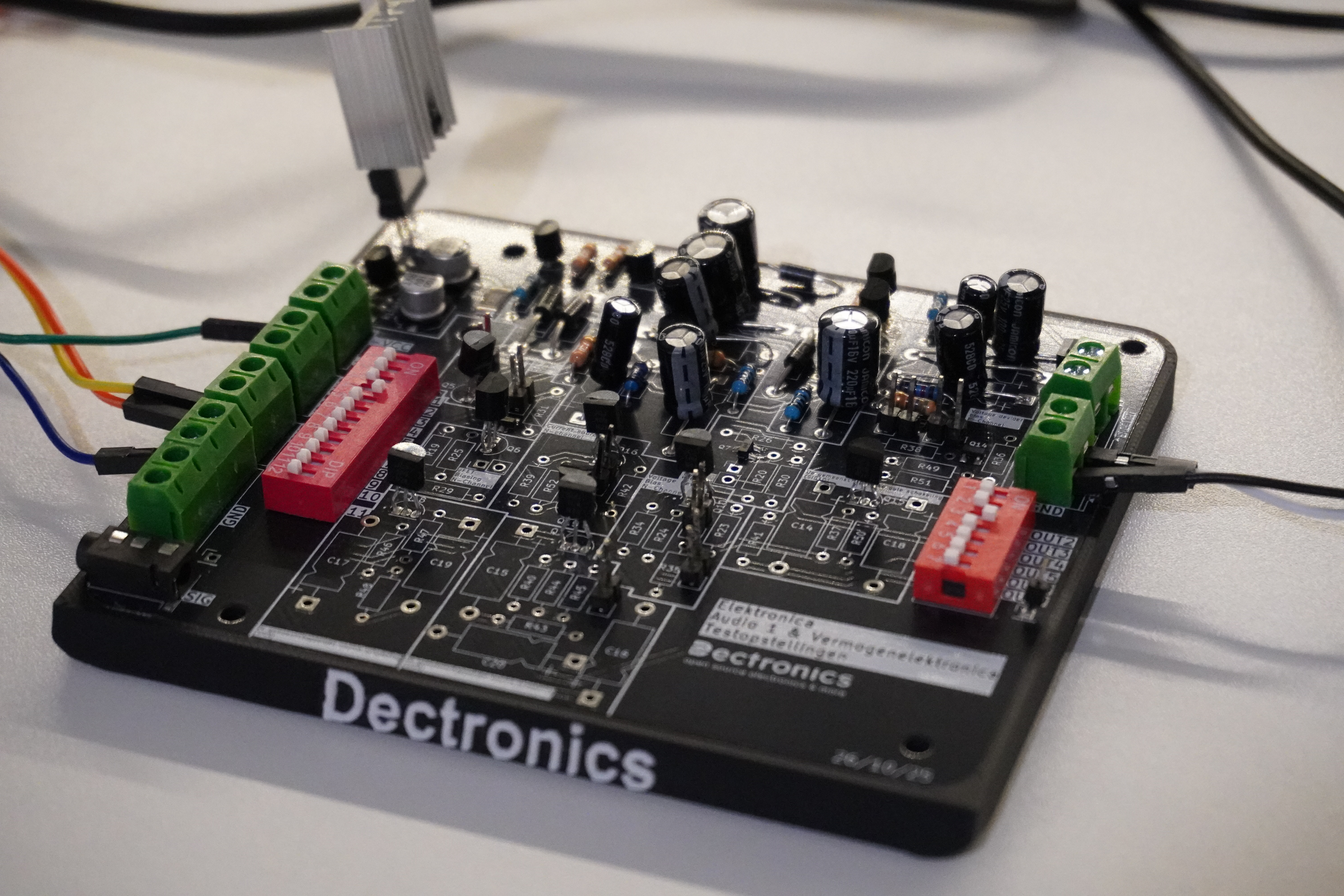
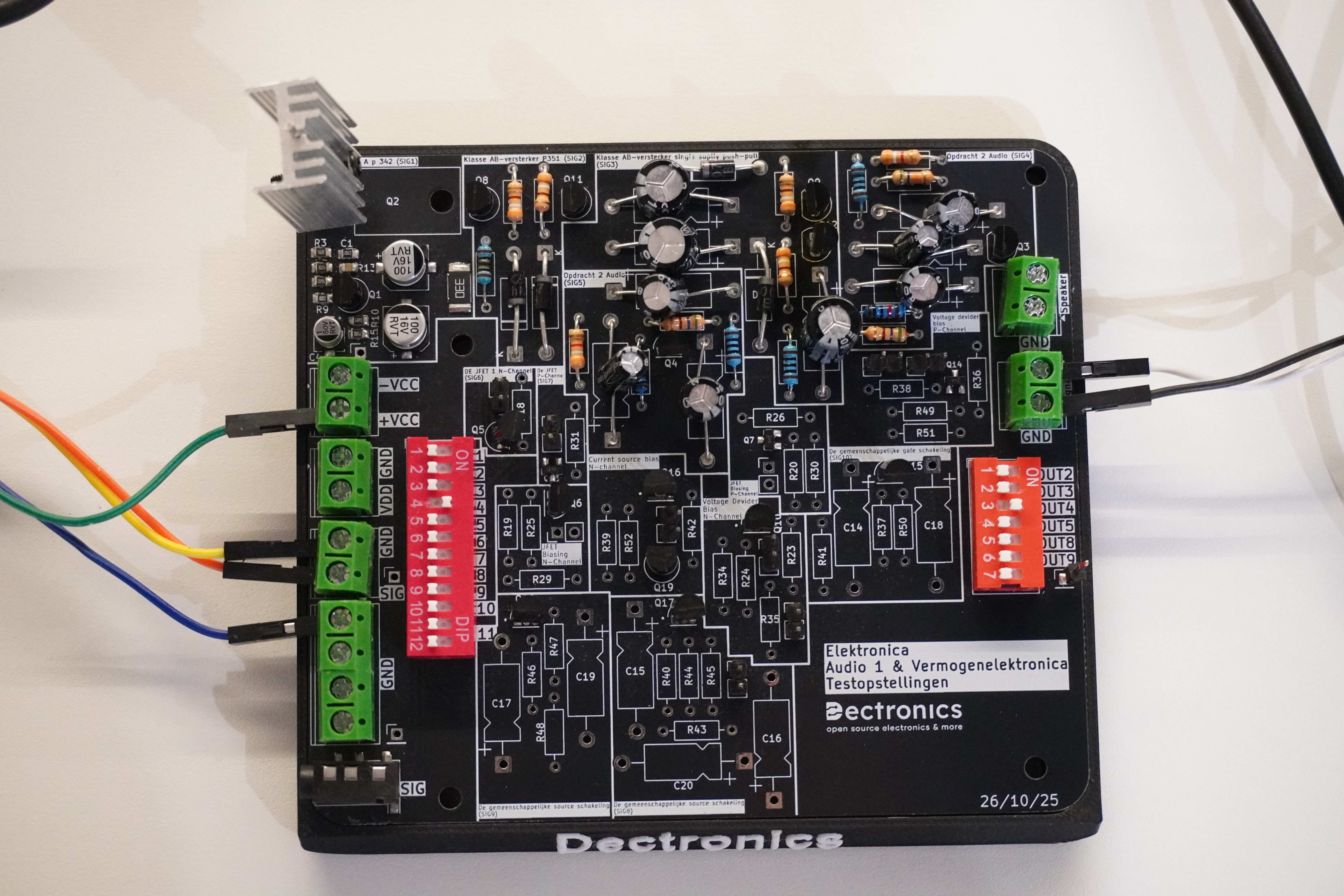
Complete printplaat met alle schakelingen voor audio 1 en vermogenelektronica @Vives kortrijk. Met een printbare voet voor betere stabiliteit en geen kortsluiting te krijgen. Op deze voet wordt er gewerkt met heated inserts (M3) voor het monteren van de print.
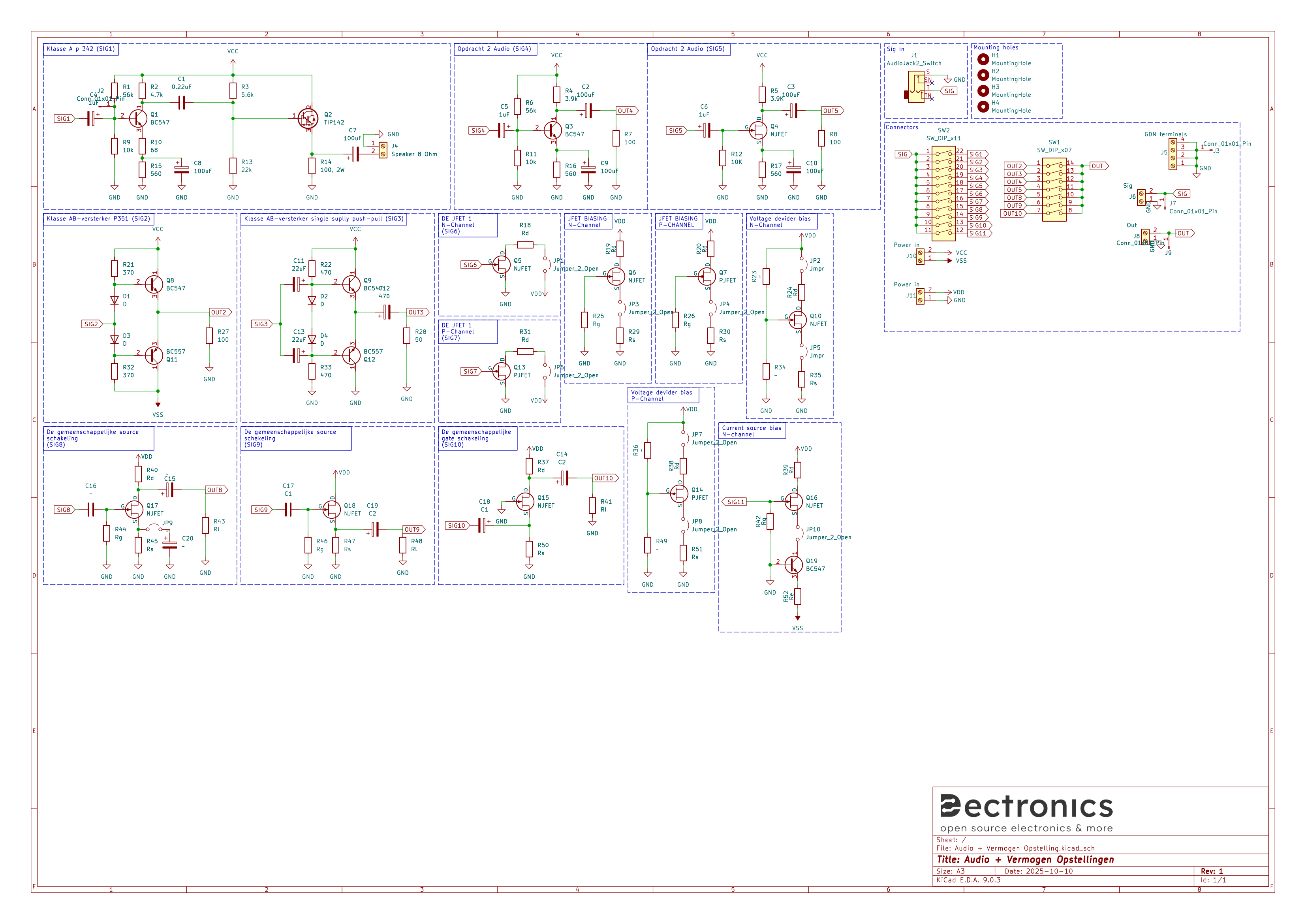
De printplaat bevat een Klasse A versterker in twee-traps configuratie met Darlington uitgang. Daarnaast is er een Klasse AB versterker met push-pull configuratie en diode bias die werkt op dual supply spanning. Voor frequentie-analyse zijn er twee circuits: een BJT common emitter configuratie en een JFET common source configuratie, beide met bypass mogelijkheden. Alle belangrijke signalen zijn toegankelijk via testpunten en connectors.
Het schema is als volgt:
Voor het solderen kan je gebruikmaken van de meegeleverde BOM file, de printplaat is een mix van SMD en TH componenten.
| Qty | Value | Footprint | References |
|---|---|---|---|
| 10 | Rd | Resistor_THT:R_Axial_DIN0207_L6.3mm_D2.5mm_P10.16mm_Horizontal | R5, R18, R19, R20, R24, R31, R37, R38, R39, R40 |
| 9 | ~ | Capacitor_THT:CP_Axial_L11.0mm_D5.0mm_P18.00mm_Horizontal | C2, C3, C5, C6, C9, C10, C15, C16, C20 |
| 8 | NJFET | J109:TRANS_J109 | Q4, Q5, Q6, Q10, Q15, Q16, Q17, Q18 |
| 8 | Rs | Resistor_THT:R_Axial_DIN0207_L6.3mm_D2.5mm_P10.16mm_Horizontal | R17, R29, R30, R35, R45, R47, R50, R51 |
| 7 | Jumper_2_Open | Connector_PinHeader_2.54mm:PinHeader_1x02_P2.54mm_Vertical | JP1, JP3, JP4, JP6, JP7, JP8, JP10 |
| 6 | Rg | Resistor_THT:R_Axial_DIN0207_L6.3mm_D2.5mm_P10.16mm_Horizontal | R12, R25, R26, R42, R44, R46 |
| 6 | ~ | Resistor_THT:R_Axial_DIN0207_L6.3mm_D2.5mm_P10.16mm_Horizontal | R6, R11, R23, R34, R36, R49 |
| 5 | BC547 | Package_TO_SOT_THT:TO-92_Inline | Q1, Q3, Q8, Q9, Q19 |
| 5 | Rl | Resistor_THT:R_Axial_DIN0207_L6.3mm_D2.5mm_P10.16mm_Horizontal | R7, R8, R41, R43, R48 |
| 4 | Conn_01x01_Pin | Connector_PinHeader_2.54mm:PinHeader_1x01_P2.54mm_Vertical | J2, J3, J7, J9 |
| 4 | D | Diode_THT:D_DO-15_P15.24mm_Horizontal | D1, D2, D3, D4 |
| 4 | MountingHole | MountingHole:MountingHole_3.2mm_M3 | H1, H2, H3, H4 |
| 3 | PJFET | MMBFJ176:SOT23 | Q7, Q13, Q14 |
| 2 | 100uF | Capacitor_SMD:CP_Elec_6.3x5.4 | C7, C8 |
| 2 | 22uF | Capacitor_THT:CP_Axial_L11.0mm_D5.0mm_P18.00mm_Horizontal | C11, C13 |
| 2 | 430 | Resistor_THT:R_Axial_DIN0207_L6.3mm_D2.5mm_P10.16mm_Horizontal | R21, R32 |
| 2 | 470 | Resistor_THT:R_Axial_DIN0207_L6.3mm_D2.5mm_P10.16mm_Horizontal | R22, R33 |
| 2 | BC557 | Package_TO_SOT_THT:TO-92_Inline | Q11, Q12 |
| 2 | C1 | Capacitor_THT:CP_Axial_L11.0mm_D5.0mm_P18.00mm_Horizontal | C17, C18 |
| 2 | C2 | Capacitor_THT:CP_Axial_L11.0mm_D5.0mm_P18.00mm_Horizontal | C14, C19 |
| 2 | Jmpr | Connector_PinHeader_2.54mm:PinHeader_1x02_P2.54mm_Vertical | JP2, JP5 |
| 2 | Power in | TerminalBlock_Phoenix:TerminalBlock_Phoenix_MKDS-1,5-2_1x02_P5.00mm_Horizontal | J10, J11 |
| 2 | Re | Resistor_THT:R_Axial_DIN0207_L6.3mm_D2.5mm_P10.16mm_Horizontal | R16, R52 |
| 1 | 0.22uF | Capacitor_SMD:C_0805_2012Metric | C1 |
| 1 | 10k | Resistor_SMD:R_0805_2012Metric_Pad1.20x1.40mm_HandSolder | R9 |
| 1 | 16 | Resistor_THT:R_Axial_DIN0207_L6.3mm_D2.5mm_P10.16mm_Horizontal | R27 |
| 1 | 1uF | Capacitor_SMD:CP_Elec_4x5.4 | C4 |
| 1 | 22k | Resistor_SMD:R_0805_2012Metric_Pad1.20x1.40mm_HandSolder | R13 |
| 1 | 33, 2W | Resistor_SMD:R_2512_6332Metric_Pad1.40x3.35mm_HandSolder | R14 |
| 1 | 4.7k | Resistor_SMD:R_0805_2012Metric_Pad1.20x1.40mm_HandSolder | R2 |
| 1 | 470 | Capacitor_THT:CP_Axial_L11.0mm_D5.0mm_P18.00mm_Horizontal | C12 |
| 1 | 5.6k | Resistor_SMD:R_0805_2012Metric_Pad1.20x1.40mm_HandSolder | R3 |
| 1 | 50 | Resistor_THT:R_Axial_DIN0207_L6.3mm_D2.5mm_P10.16mm_Horizontal | R28 |
| 1 | 560 | Resistor_SMD:R_0805_2012Metric_Pad1.20x1.40mm_HandSolder | R15 |
| 1 | 56k | Resistor_SMD:R_0805_2012Metric_Pad1.20x1.40mm_HandSolder | R1 |
| 1 | 68 | Resistor_SMD:R_0805_2012Metric_Pad1.20x1.40mm_HandSolder | R10 |
| 1 | AudioJack2_Switch | Connector_Audio:Jack_3.5mm_KoreanHropartsElec_PJ-320D-4A_Horizontal | J1 |
| 1 | GDN terminals | TerminalBlock_Phoenix:TerminalBlock_Phoenix_MKDS-1,5-4-5.08_1x04_P5.08mm_Horizontal | J5 |
| 1 | LOGO | Drawings_Customs:Dectronics_Sub_20mm | G*** |
| 1 | Out | TerminalBlock_Phoenix:TerminalBlock_Phoenix_MKDS-1,5-2_1x02_P5.00mm_Horizontal | J8 |
| 1 | Rc | Resistor_THT:R_Axial_DIN0207_L6.3mm_D2.5mm_P10.16mm_Horizontal | R4 |
| 1 | SW_DIP_x07 | Button_Switch_THT:SW_DIP_SPSTx07_Slide_9.78x19.96mm_W7.62mm_P2.54mm | SW1 |
| 1 | SW_DIP_x11 | Button_Switch_THT:SW_DIP_SPSTx11_Slide_9.78x30.12mm_W7.62mm_P2.54mm | SW2 |
| 1 | Sig | TerminalBlock_Phoenix:TerminalBlock_Phoenix_MKDS-1,5-2_1x02_P5.00mm_Horizontal | J6 |
| 1 | Speaker 8 Ohm | TerminalBlock_Phoenix:TerminalBlock_Phoenix_MKDS-1,5-2_1x02_P5.00mm_Horizontal | J4 |
| 1 | TIP142 | Package_TO_SOT_THT:TO-220-3_Horizontal_TabDown | Q2 |
| 1 | ~ | Connector_PinHeader_2.54mm:PinHeader_1x02_P2.54mm_Vertical | JP9 |
emiirkaya/ThermovitalSync-PCB
A PCB project for a vital monitoring-cooling device with GUI


prydin/opamp-frontend-class-ab
The result is a fast amplifier (>80V/us slew rate) with low distortion (0.00045% meadured @ 1kHz/1W/8ohm resistive load). It's undergone some preliminary measurements and looks quite promising.


dotnet/iot
This repo includes .NET Core implementations for various IoT boards, chips, displays and PCBs.

robsonsmartins/usbflashprog
A memory device programmer (Flash/EPROM/E2PROM) board and software, connected to PC by USB port.
It measures 114.9 × 100 mm and has 2 copper layers, 1.6 mm thick.
123 parts, built around the BC547, BC557 and TIP142. The full list of its parts is on this page, with links to each part's symbol and footprint where PCBKit's library has them.
From the TiebeDeclercq/Audio-1-Labo-Opstelling repository on GitHub, at the commit this page was made from: the board is Printplaat/Audio + Vermogen Opstelling.kicad_pcb and its schematic Printplaat/Audio + Vermogen Opstelling.kicad_sch. PCBKit opens the board in the browser, with nothing to install.
Its repository states no licence, so its author keeps all rights: ask TiebeDeclercq before reusing the design.