2 layers90 × 50 mm

 ThomasStaeudelmayr/LedDriver
ESP controlled 4 Channel Led Driver (RGBW)
Led driver cc v2 is an open-source printed circuit board by ThomasStaeudelmayr, from the ThomasStaeudelmayr/LedDriver repository on GitHub. It is a 2-layer board of 90 × 63 mm with 61 parts on 44 nets, routed with 287 tracks and 115 vias.
It is built around the TSR 1-2490, LM3404B and SMAJ40A. Its parts include 28 capacitors, 8 resistors, 5 ICs, 5 diodes and 4 inductors.


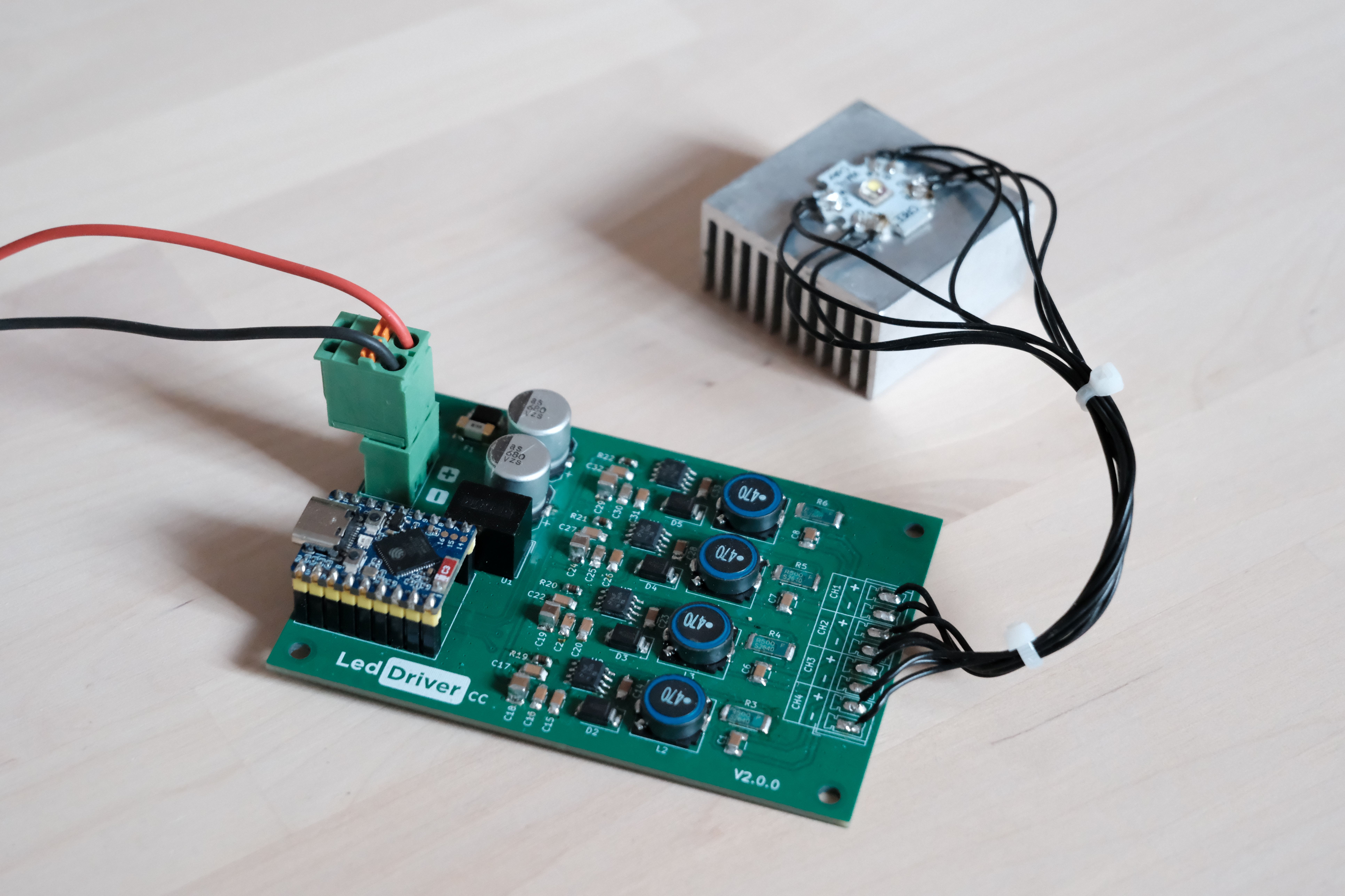
This repository contains two distinct 4-channel LED driver hardware designs controlled by an ESP32-S3 Zero. Both versions support pulse-width modulation dimming.
Constant Current (CC) Driver: Designed for high-power LEDs (like the Cree XLamp Color Series) that require current regulation.
Constant Voltage (CV) Driver: Features 4 power MOSFETs designed for dimming standard 12V/24V RGBW LED strips.
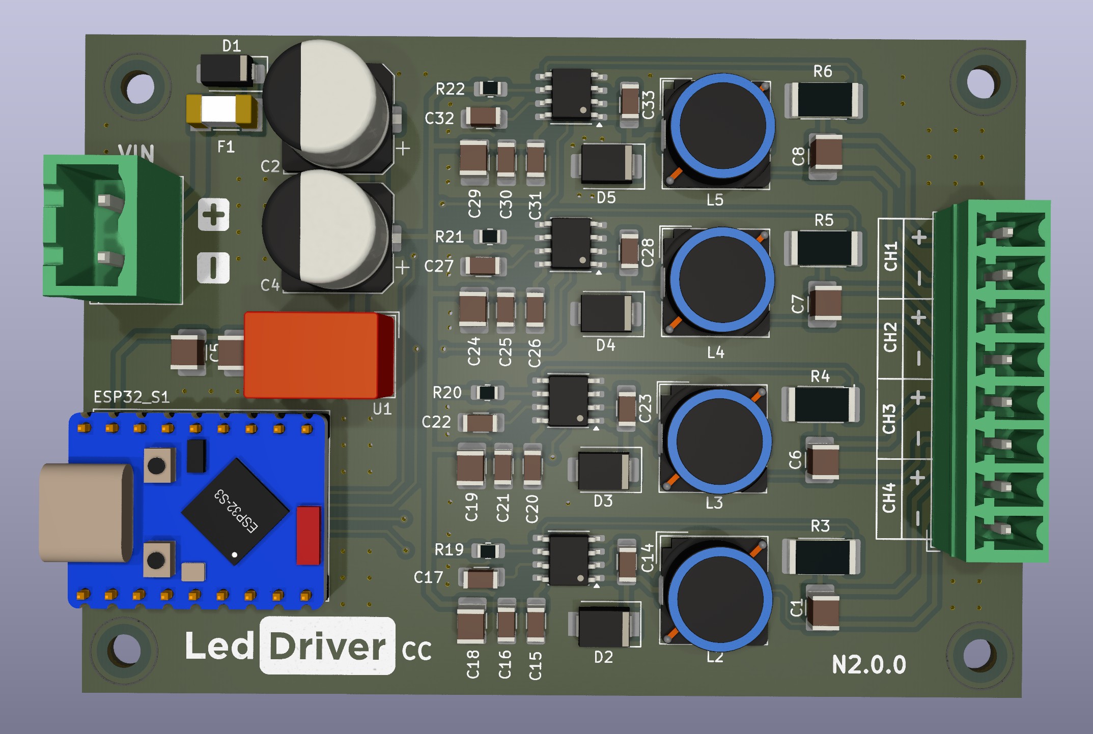
The CC version is built around the LM3404 LED driver IC. This is a step-down switching regulator that drives the connected LEDs in constant current mode, eliminating the need for current-limiting resistors and increasing system efficiency.
The maximum forward current ($I_F$) delivered to the LEDs is determined by the value of the sense resistor ($R_{SNS}$) connected to the CS pin. Use the following formula to select your resistor value:
$$R_{SNS} = \frac{V_{REF}}{I_F} = \frac{0.2\text{ V}}{I_F}$$
Using a 0.2 $\Omega$ resistor sets the maximum forward current to 1.0 A.
| Part name | Quantity | Order number | Distributor |
|---|---|---|---|
| ESP32-S3-Zero | 1 | B0GV459V87 | Amazon |
| LM3404 | 4 | LM 3404 MA | Reichelt |
| DK_SLF10145 47uH | 4 | 810-SLF10145T | Mouser |
| 0R2 2512 | 4 | 708-RNCL2512FTR200 | Mouser |
| SMAJ40A | 4 | 652-SMAJ40A | Mouser |
| DCDC Converter | 1 | LME78_05-1.0 | Reichelt |
| MCV_1,5_8-G-3.81 | 1 | 220-4888 | RS |
| Fuse 5A | 1 | 576-0454005.NR | Mouser |
| MSTBVA 2-G 5,08 | 1 | STBVA 2-G 5,08 | Reichelt |
| Capacitor 470uF 10x10 35V | 2 | - | - |
| Capacitor 470nF 1210 50V | 4 | - | - |
| Capacitor 2.2uF 1206 50V | 4 | - | - |
| Capacitor 100nF 1206 50V | 8 | - | - |
| Capacitor 10uF 1210 50V | 6 | - | - |
| Resistor 500k 0805 | 4 | - | - |
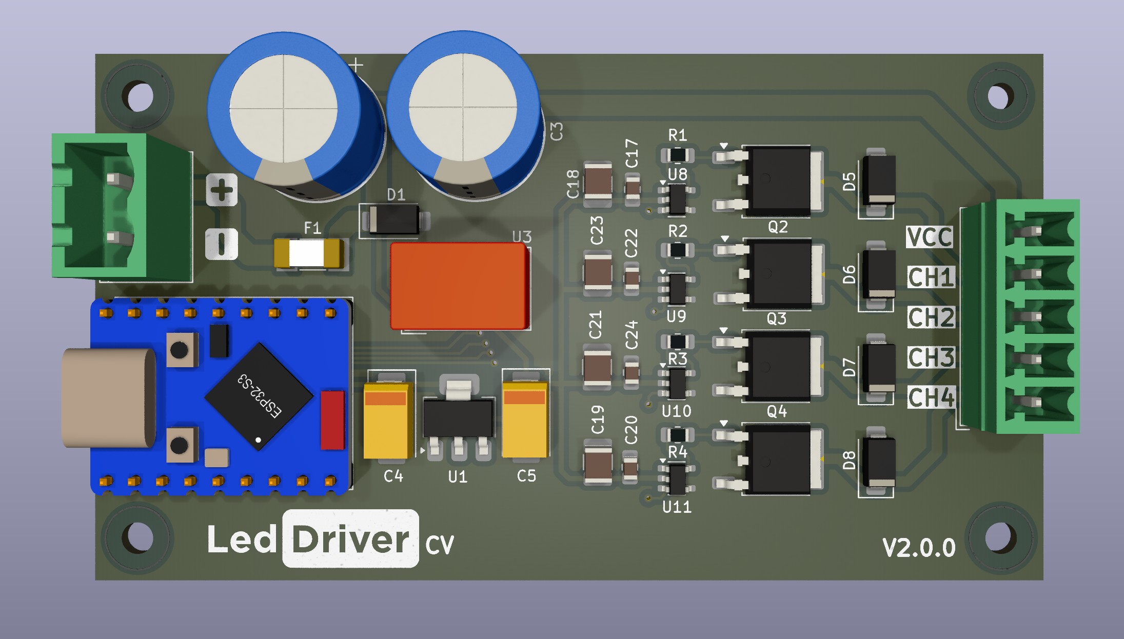
The constant voltage version is designed for standard 12V/24V RGBW LED strips with integrated current-limiting resistors, utilizing 4 power MOSFETs as low-side switches. Dedicated gate drivers rapidly charge the MOSFET gate capacitance. The resulting fast rise and fall times minimize switching power losses during high-frequency PWM operation.
| Part name | Quantity | Order number | Distributor |
|---|---|---|---|
| ESP32-S3-Zero | 1 | B0GV459V87 | Amazon |
| MCV_1,5_5-G-3.81 | 1 | 651-1803455 | Mouser |
| MSTBVA 2-G 5,08 | 1 | STBVA 2-G 5,08 | Reichelt |
| Capacitor 470uF 35V | 2 | FR-A 470U 63B | Reichelt |
| SMAJ40A | 5 | 652-SMAJ40A | Mouser |
| Tantal 7343 100uF 16V | 2 | 80-T495D107M16ATE060 | Mouser |
| 5V LDO | 1 | 511-LD1117S50 | Mouser |
| 9V DCDC Converter | 1 | TSRN 1-2490 | Reichelt |
| MCP1416 SOT-23-5 | 4 | 579-MCP1416RTEOTVAO | Mouser |
| Mosfet STD80N6F6 | 4 | 511-STD80N6F6 | Mouser |
| Fuse 5A | 1 | 576-0454005.NR | Mouser |
| Capacitor 10uF 1210 50V | 4 | - | - |
| Capacitor 100nF 0805 50V | 4 | - | - |
| Resistor 10R 0805 | 4 | - | - |
The PC sends color values over a USB serial connection to the Led Driver Bridge, which then wirelessly sends those values to the Led Driver Receiver.
To pair the devices, you need the unique MAC address of the receiver board.
The transmitter connects to your PC via USB, listens for incoming serial data, and forwards it wirelessly.
// Example: Replace with your actual receiver MAC address
uint8_t broadcastAddress[] = {0x34, 0xB7, 0xDA, 0x5B, 0x58, 0xE0};The bridge ESP expects a single string formatted as R:G:B:W followed by a newline character (\n).
Example: 1024:255:150:360
You can type this manually into the Arduino Serial Monitor or automate it using a program. This repository contains two python and one html example that generate the rgbw values. Once the transmitter gets a valid message, it splits the string into individual color values and sends them out over ESP-NOW.
LedDriver_web_app_rgbw.html - control leds via a browser LedDriver_control_hsv.py - control leds via a python script LedDriver_rgbw_waves.py - python script that generates led animation
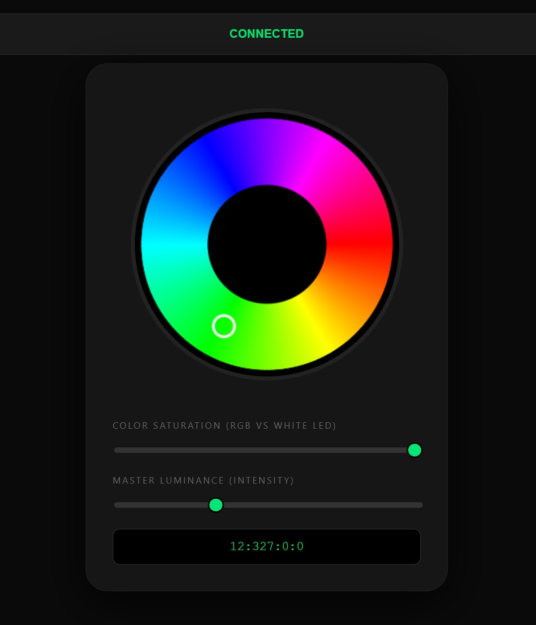
The Web Server example eliminates the need for a dedicated transmitter controller. The ESP32 on the driver board will act as a web server. After altering the Wi-Fi name and password and uploading the code the leds can be controlled on: http://ledcontrol.local
| Qty | Value | Footprint | References |
|---|---|---|---|
| 8 | 100nF | Capacitor_SMD:C_1206_3216Metric_Pad1.33x1.80mm_HandSolder | C16, C17, C21, C22, C26, C27, C31, C32 |
| 6 | 10uF | Capacitor_SMD:C_1210_3225Metric_Pad1.33x2.70mm_HandSolder | C3, C5, C18, C19, C24, C29 |
| 4 | 0.2R | Resistor_SMD:R_2512_6332Metric_Pad1.40x3.35mm_HandSolder | R3, R4, R5, R6 |
| 4 | 10nF | Capacitor_SMD:C_1206_3216Metric_Pad1.33x1.80mm_HandSolder | C14, C23, C28, C33 |
| 4 | 2,2UF | Capacitor_SMD:C_1206_3216Metric_Pad1.33x1.80mm_HandSolder | C15, C20, C25, C30 |
| 4 | 470nF | Capacitor_SMD:C_1210_3225Metric_Pad1.33x2.70mm_HandSolder | C1, C6, C7, C8 |
| 4 | 47µH | Inductor_SMD:L_TDK_SLF10145 | L2, L3, L4, L5 |
| 4 | 536k | Resistor_SMD:R_0805_2012Metric_Pad1.20x1.40mm_HandSolder | R19, R20, R21, R22 |
| 4 | D_Schottky | Diode_SMD:D_SMB | D2, D3, D4, D5 |
| 4 | LM3404 | Package_SO:SOIC-8_3.9x4.9mm_P1.27mm | U2, U3, U4, U5 |
| 4 | MountingHole | MountingHole:MountingHole_3.2mm_M3 | H1, H2, H3, H4 |
| 3 | LOGO | LOGO | G***, G***, G*** |
| 2 | 470uF | Capacitor_SMD:CP_Elec_10x10 | C2, C4 |
| 1 | 1A | custom_footprints:Fuse_Littelfuse-NANO2-451_453 | F1 |
| 1 | Conn_01x02_Female | Connector_Phoenix_MSTB:PhoenixContact_MSTBVA_2,5_2-G_1x02_P5.00mm_Vertical | J3 |
| 1 | Conn_01x08_Pin | Connector_Phoenix_MC:PhoenixContact_MCV_1,5_8-G-3.81_1x08_P3.81mm_Vertical | J1 |
| 1 | SMAJ40A | Diode_SMD:D_SMA | D1 |
| 1 | TSR_1-2490 | Converter_DCDC:Converter_DCDC_TRACO_TSR-1_THT | U1 |
| 1 | ~ | custom_footprints:ESP32-S3-Zero | ESP32_S1 |

klaus-liebler/sensact
Es gibt vier Namespaces für Nachrichten "REQUEST" und "RESPONSE", "EVENT" und "ACKNOWLEDGE". Dies wird mit den beiden LSB des Versions-Namespace-Bytes erklärt (Somit bleiben 64 Versionierungsmöglichkeiten) Alle vier…

sunipkm/kicad-auto-importer
A Rust workspace with two companion desktop applications for KiCad, built on a shared, GUI-agnostic core library — each has its own README with full details:


Kaptain2026/AUDIO-AMPLIFIER-PCB-DESIGN
I designed an audio amplifier pcb for my personal consumption. It has controls for Bass, Tremble and Volume. In addition you can connect to it through Bluetooth and play your music directly.


Many3Stars/Another-IoT-network-for-monitoring-forests
Author: Manuel Álvarez Herrera Supervisor: José Antonio García Souto Year: 2024

shanteacontrols/OpenDeck
A platform for building interactive control and sensing devices using MIDI and OSC built with Zephyr RTOS.

Neumi/open_echo
Open Source echo sounder / depth sounder / SONAR for bathymetry and research. Arduino based and compatible.
It measures 90 × 63 mm and has 2 copper layers, 1.6 mm thick.
61 parts, built around the TSR 1-2490, LM3404B and SMAJ40A. The full list of its parts is on this page, with links to each part's symbol and footprint where PCBKit's library has them.
From the ThomasStaeudelmayr/LedDriver repository on GitHub, at the commit this page was made from: the board is hardware/ledDriver_cc/led_driver_cc_v2.1/led_driver_cc_v2.kicad_pcb and its schematic hardware/ledDriver_cc/led_driver_cc_v2.1/led_driver_cc_v2.kicad_sch. PCBKit opens the board in the browser, with nothing to install.
Its repository states no licence, so its author keeps all rights: ask ThomasStaeudelmayr before reusing the design.