

4 layers35 × 32.3 mm

An open source, low cost, extensible brushed drone.
Astra is an open-source printed circuit board by TheScientist101, from the TheScientist101/astra repository on GitHub. It is a 4-layer board of 43.2 × 43.2 mm with 93 parts on 111 nets, routed with 864 tracks and 120 vias.
It is built around the BMP388, HYCW110-TF10-180B and BMI270, with the TLV1117LV33DCYR, AO3400A and WS2812B among its other parts. Its parts include 27 capacitors, 17 resistors, 8 diodes, 7 ICs and 4 transistors. It belongs with the robots and motor control boards and the STM32 boards of this library.



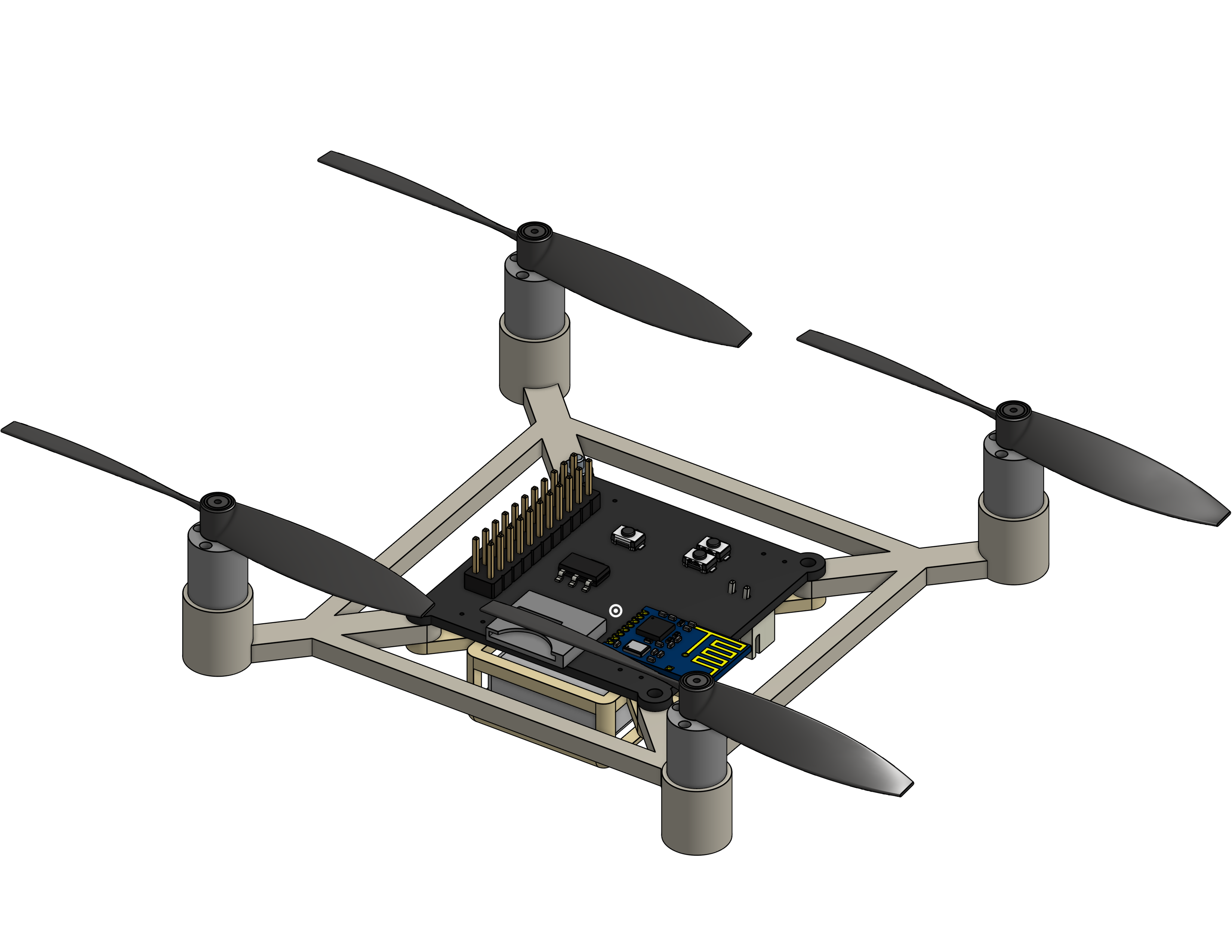
Astra is an ~80mm brushed quadcopter. It it powered off of a single 1s Li-Po (4.2V), and uses four brushed motors.
Astra supports an optional FPV module, and includes a HAT-style pin interface on the flight controller.
We've also designed our own transmitter for Astra. The flight controller and transmitter use an nRF24 to communicate with low latency.
Every part of Astra was designed from scratch - the flight controller, the transmitter, and the frame.
Siddhant and I both love making things, but we've never made anything that moves before. What cooler of a thing is there that moves than a drone? With air voyage in our control, it would open the gate to even cooler projects, like imagine if you could play laser tag with a drone as your teammate or if you could have a drone that follows you around and takes pictures of you. The possibilities are endless!
That's why we decided to make our drone extensible. To me, modularity is the coolest part of any gadget. It allows you to add new features and capabilities without having to redesign the entire thing. Astra has a HAT-style pin interface called the DUCKDUCKGOOSE (Digital Unified Centralized Kibibit Device Universal Coding Knowledge Generic Operable Objective Service Extensible) Connector on the flight controller, which allows you to add new peripherals and sensors easily.
On the other hand, most drone projects we've seen online are expensive. While Hack Club is dope enough to have a program that gives us free hardware, it is difficult to find a "DIY" drone that is relatively cheap that flies well. Since we wanted to make sure that our drone was actually good at flying, we decided to remove the onboard camera that we had in our initial design in place of a more traditional FPV system rather than just trying to make our own.
All of the components for the drone and can be bought for around $75. (See the BOM for more details!)
The bulk of this is actually the cost to buy the PCBs and stencil (which is anticipated to be around $25). The actual component cost is closer to $50.
Note: Adding an FPV system to the drone is relatively costly. The FPV Camera + VTX module costs
$25, which is actually on the cheaper end for these systems. The total cost with the FPV module is slightly less than$100before taxes and other fees.
(for hackclub) Even though the total cost of this drone is under $150, we will likely need to have multiple iterations of the PCB before we can get it working right.
The Flight Controller uses an STM32H750. This is a powerful chip with plenty of GPIO pins for peripherals. We plan to implement a software OSD within the H7 for the FPV interface.
PCB files can be found within the drone/pcb/ folder.
The Flight Controller uses the betaflight firmware. A betaflight config file as well as flashing instructions can be found in the drone/firmware/ folder
The frame for the FC was designed in Onshape. CAD files can be found in drone/cad/;
Peripherals:
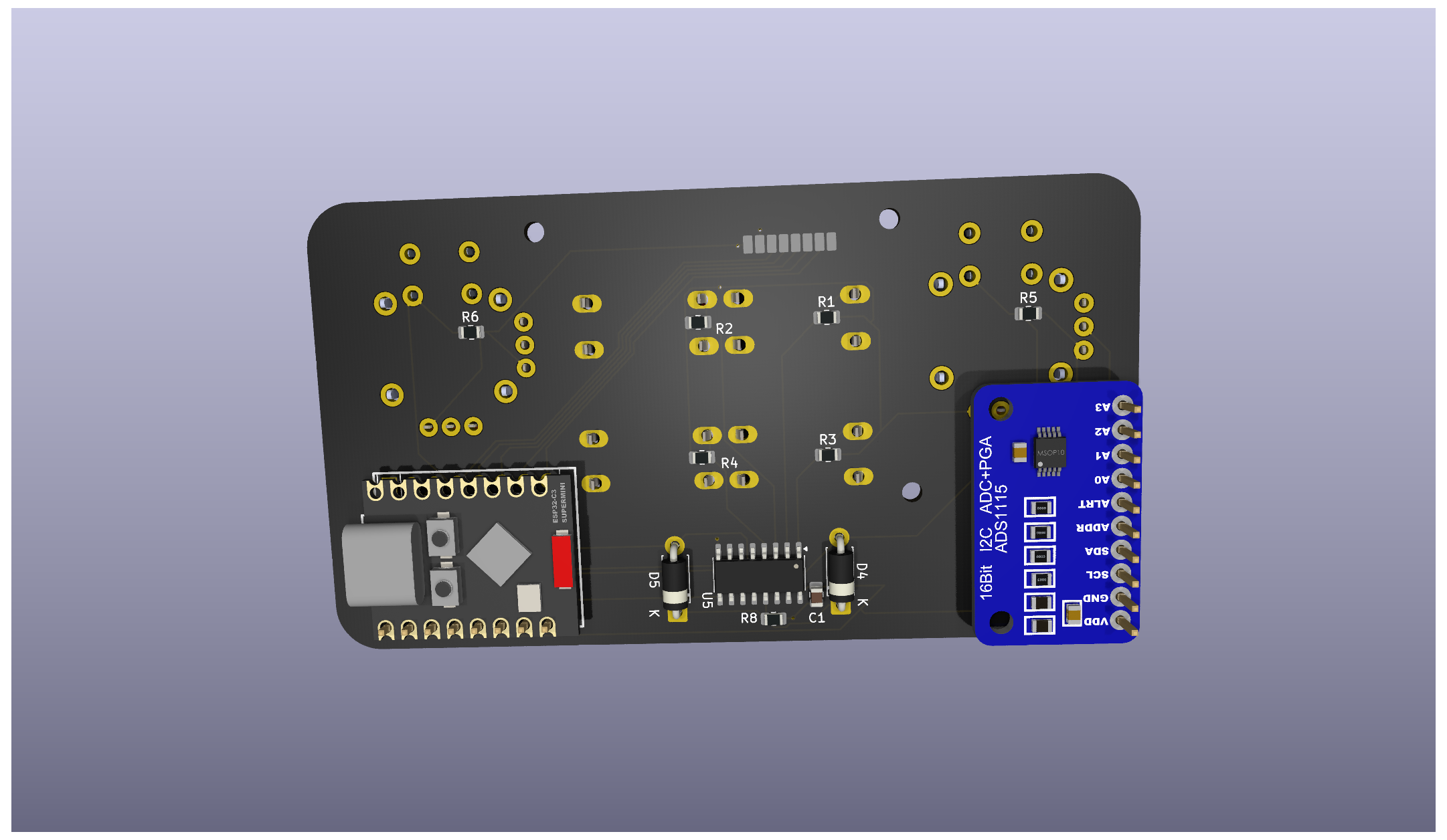
BMI270 - IMUBMP388 - BarometerWS2812BsThe Ground Transmitter uses an ESP32-C3-SuperMini (a C3 chip similar to the XIAO that we already have on hand). It features:
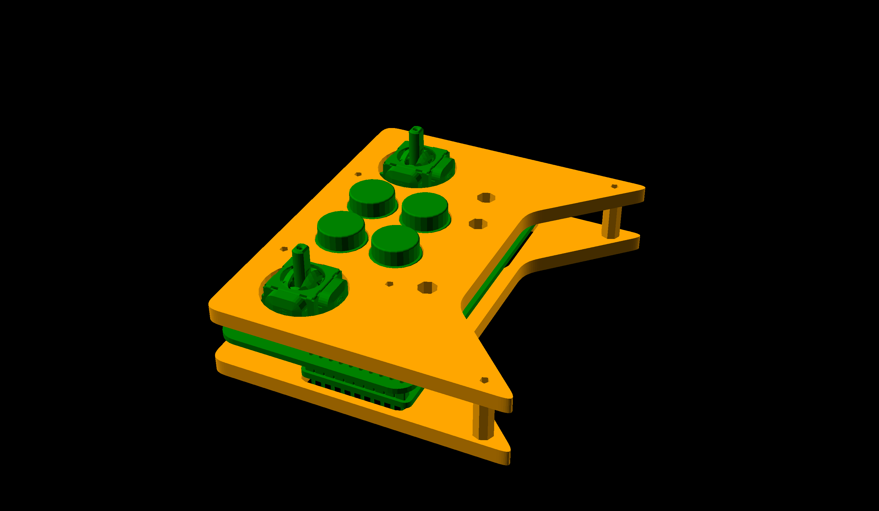
WS2812BsThe PCB, firmware, and case for the transmitter can be found in the controller/ folder
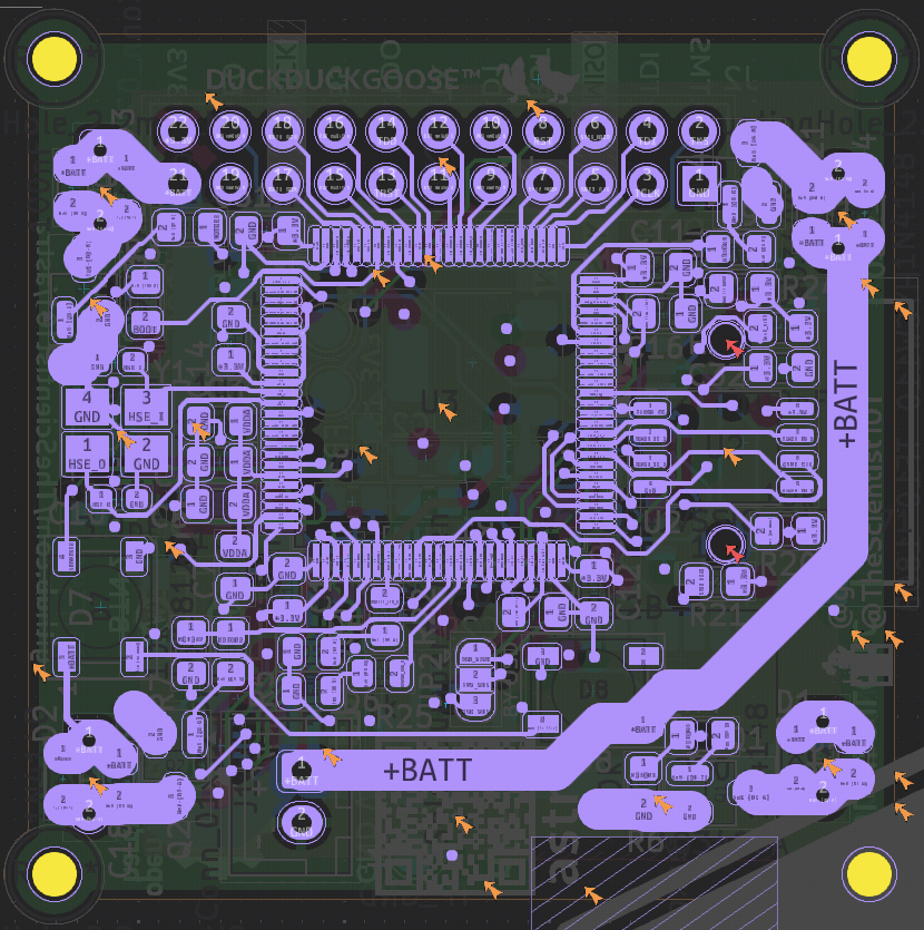
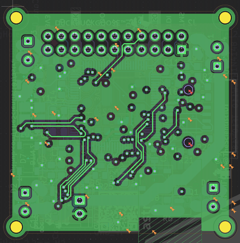
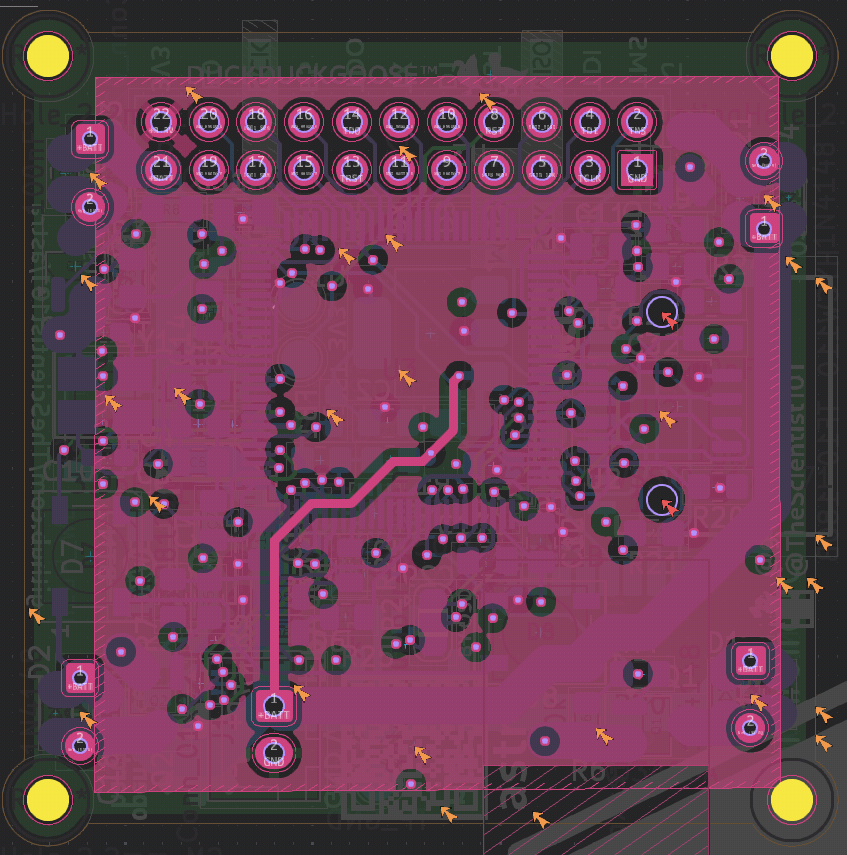
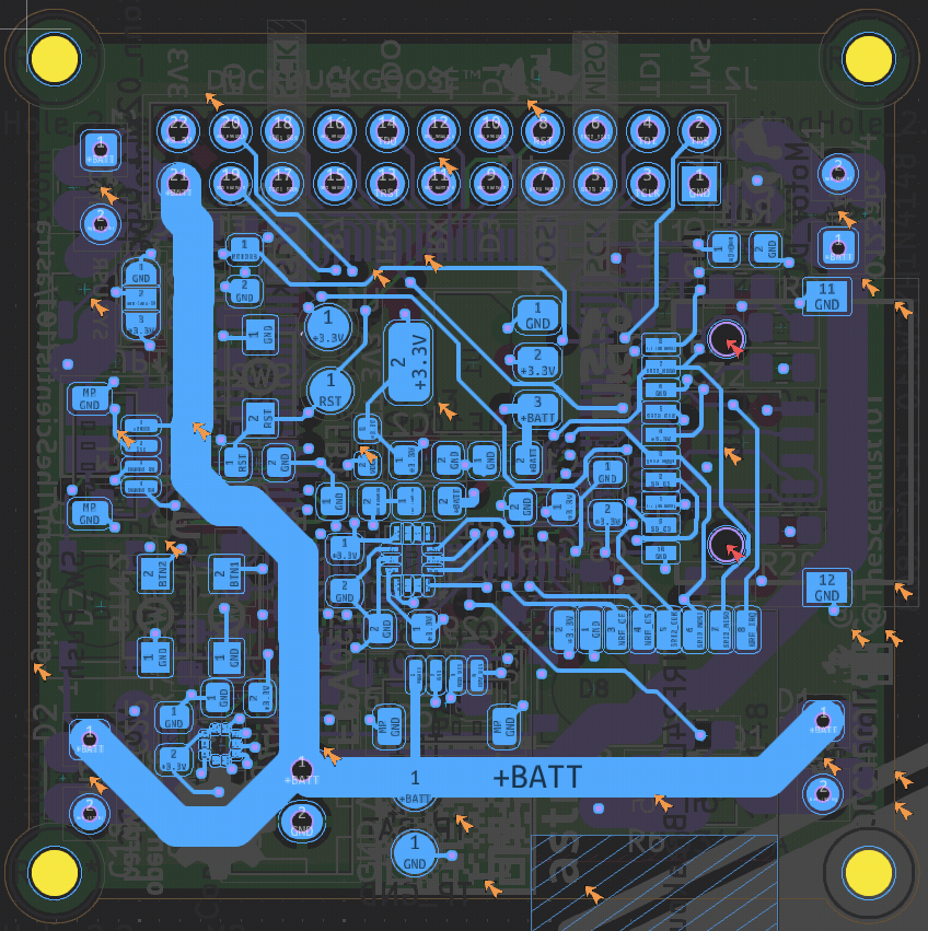
Copper Layers:
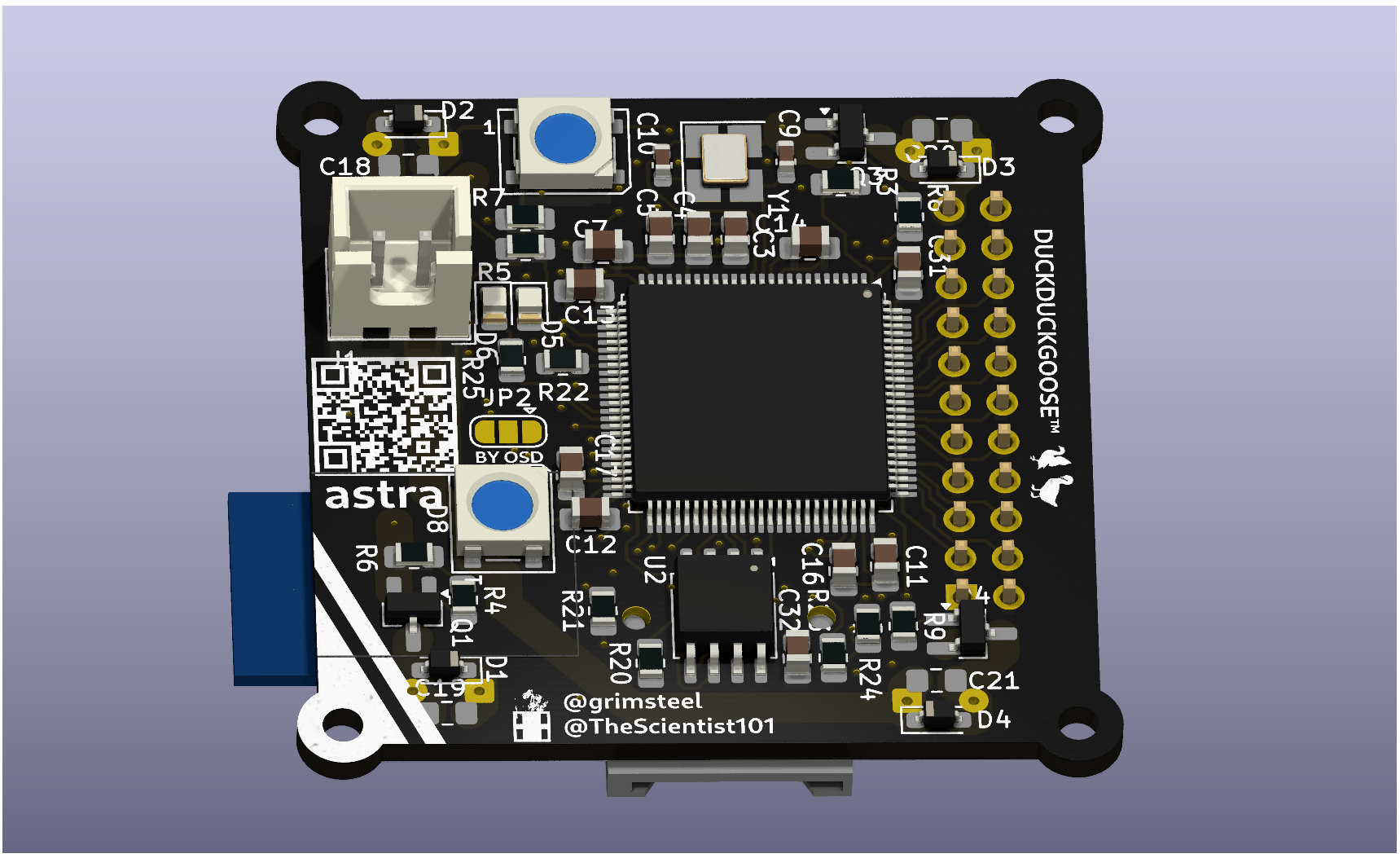
PCB 3D Render:
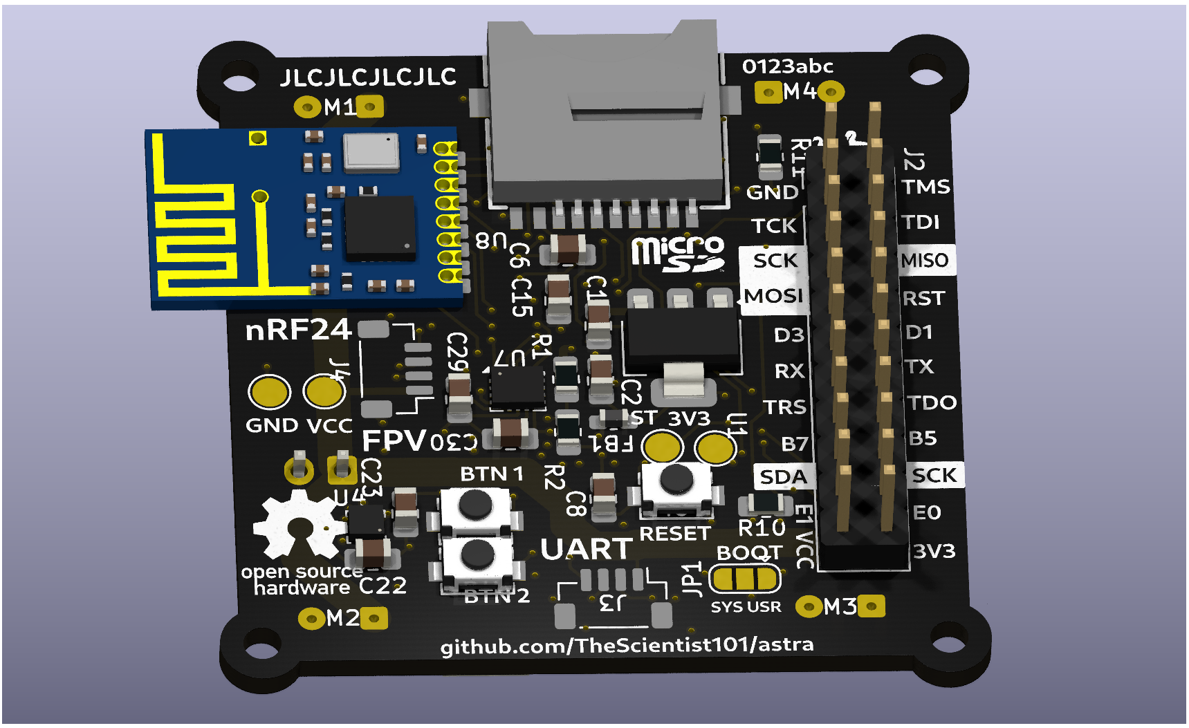
Controller PCB Render:
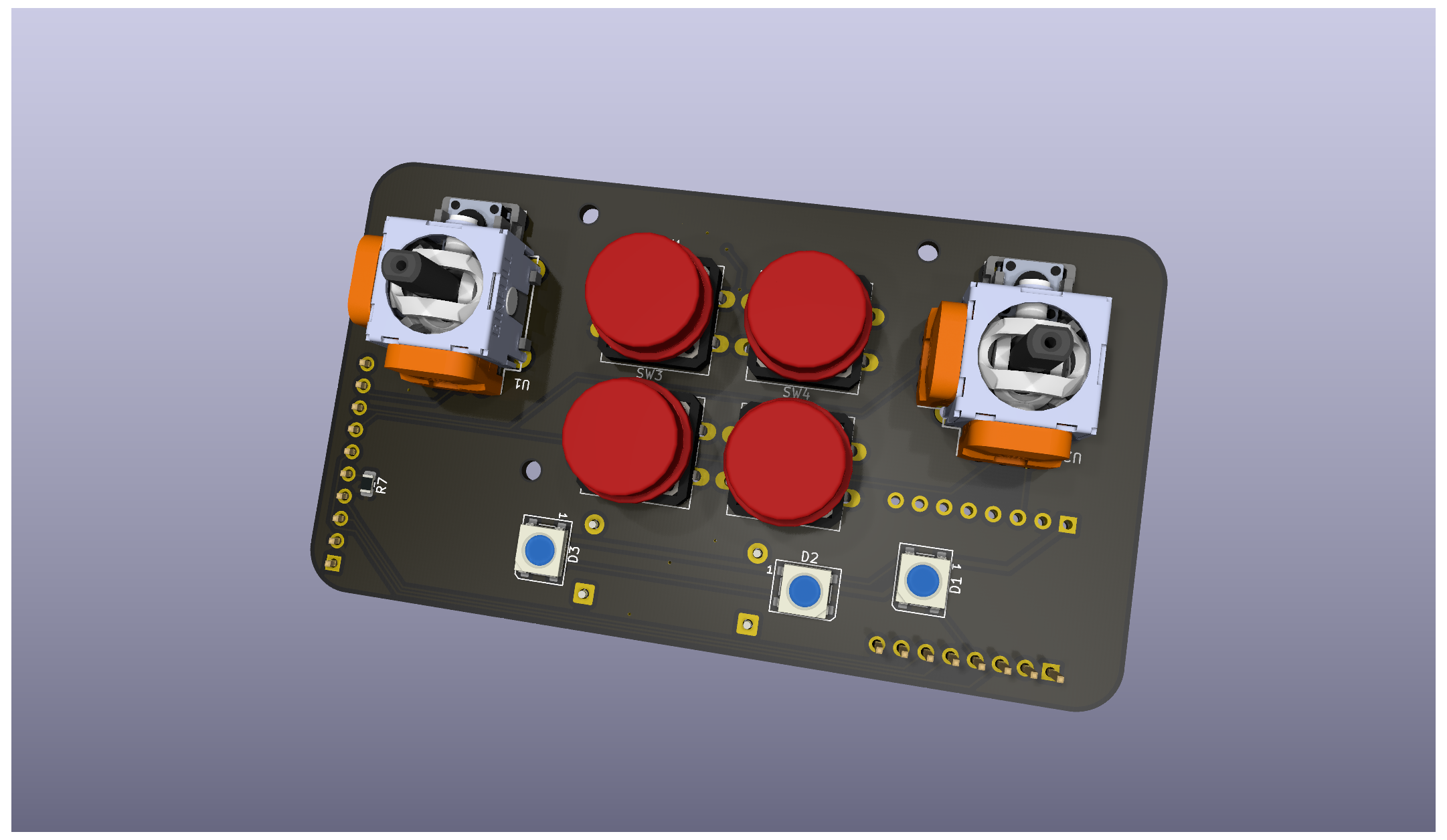
Controller Assembled Render:
| Qty | Value | Footprint | References |
|---|---|---|---|
| 18 | 100nF | Capacitor_SMD:C_0805_2012Metric_Pad1.18x1.45mm_HandSolder | C4, C6, C11, C12, C13, C14, C18, C19, C20, C21, C22, C23, C29, C30, C31, C32 +2 |
| 9 | 10k | Resistor_SMD:R_0805_2012Metric_Pad1.20x1.40mm_HandSolder | R3, R6, R7, R10, R11, R20, R21, R23, R24 |
| 6 | LOGO | LOGO | G***, G***, G***, G***, G***, G*** |
| 4 | 1N4148 | Diode_SMD:D_SOD-323_HandSoldering | D1, D2, D3, D4 |
| 4 | 220 | Resistor_SMD:R_0805_2012Metric_Pad1.20x1.40mm_HandSolder | R4, R5, R8, R9 |
| 4 | AO3400A | Package_TO_SOT_SMD:SOT-23_Handsoldering | Q1, Q2, Q3, Q4 |
| 4 | Motor_DC | Connector_Wire:SolderWire-0.1sqmm_1x02_P3.6mm_D0.4mm_OD1mm | M1, M2, M3, M4 |
| 3 | SW_Push | lcsc:SW-SMD_L4.0-W2.9-LS5.0 | SW1, SW2, SW3 |
| 2 | 0.2uF | Capacitor_SMD:C_0805_2012Metric_Pad1.18x1.45mm_HandSolder | C16, C17 |
| 2 | 100k | Resistor_SMD:R_0805_2012Metric_Pad1.20x1.40mm_HandSolder | R1, R2 |
| 2 | 10uF | Capacitor_SMD:C_0805_2012Metric_Pad1.18x1.45mm_HandSolder | C1, C2 |
| 2 | 1k | Resistor_SMD:R_0805_2012Metric | R22, R25 |
| 2 | 1uF | Capacitor_SMD:C_0805_2012Metric_Pad1.18x1.45mm_HandSolder | C3, C5 |
| 2 | 3.9pF | Capacitor_SMD:C_0603_1608Metric_Pad1.08x0.95mm_HandSolder | C9, C10 |
| 2 | Conn_01x04_MountingPin | Connector_JST:JST_SH_BM04B-SRSS-TB_1x04-1MP_P1.00mm_Vertical | J3, J4 |
| 2 | LED | LED_SMD:LED_0805_2012Metric | D5, D6 |
| 2 | SolderJumper_3_Open | Jumper:SolderJumper-3_P1.3mm_Open_RoundedPad1.0x1.5mm | JP1, JP2 |
| 2 | WS2812B | LED_SMD:LED_WS2812B_PLCC4_5.0x5.0mm_P3.2mm | D7, D8 |
| 1 | 25 MHz | Crystal:Crystal_SMD_3225-4Pin_3.2x2.5mm_HandSoldering | Y1 |
| 1 | 4.7uF | Capacitor_SMD:C_0805_2012Metric_Pad1.18x1.45mm_HandSolder | C15 |
| 1 | 601T05 | Inductor_SMD:L_0603_1608Metric_Pad1.05x0.95mm_HandSolder | FB1 |
| 1 | BMI270 | Package_LGA:Bosch_LGA-14_3x2.5mm_P0.5mm | U7 |
| 1 | BMP388 | Package_LGA:ST_HLGA-10_2x2mm_P0.5mm_LayoutBorder3x2y | U4 |
| 1 | Conn_01x02_Pin | Connector_Wire:SolderWire-0.1sqmm_1x02_P3.6mm_D0.4mm_OD1mm | J1 |
| 1 | Conn_02x11_Odd_Even | Connector_PinHeader_2.54mm:PinHeader_2x11_P2.54mm_Vertical | J2 |
| 1 | HYCW110-TF10-180B | lcsc:SIM-SMD_HYCW110-TF10-180B | U8 |
| 1 | NRF24L01_Breakout | lcsc:nRF24L01_SMD_Breakout | U5 |
| 1 | STM32H750VBTx | Package_QFP:LQFP-100_14x14mm_P0.5mm | U3 |
| 1 | TLV1117LV33DCYR | Package_TO_SOT_SMD:SOT-223-3_TabPin2 | U1 |
| 1 | TP_3.3 | TestPoint:TestPoint_Pad_D2.0mm | TP2 |
| 1 | TP_BAT | TestPoint:TestPoint_Pad_D2.0mm | TP1 |
| 1 | TP_GND | TestPoint:TestPoint_Pad_D2.0mm | TP4 |
| 1 | TP_RST | TestPoint:TestPoint_Pad_D2.0mm | TP3 |
| 1 | W25Q64JVSSIQ_C179171 | Package_SO:SOIC-8_5.3x5.3mm_P1.27mm | U2 |
| 1 | https://github.com/TheScientist101/astra | lcsc:qrcode | QR***** |
The 89 most common of 93 parts.


grimsteel/slam
Project progress: - [x] SLAM implementation (theoretical) - [x] Robot w/ lidar - [x] Dead reckoning - [x] Linear motion model - [x] Landmark detection (LiDAR) - [ ] STM EKF filter - [ ] STM EKF-SLAM (& landmark storage)


si-nalsal/pcb-mantis
A servo-based UAV flight controller built around the STM32H743IIK6 (Cortex-M7, UFBGA-201, 0.65 mm pitch). The board distributes power to a fixed-wing/multirotor airframe with 16 PWM servo outputs, redundant IMU and…

victorhook/f8-fc
f8 fc is a fully open source AIO flight controller with 8 motor drives

desanv01/Flight-Controller-V2
STM32H743 controller: regulated power, signal-only ESC, neutral ArduPilot firmware, manufacturing data and engineering history.

Twisted-Fields/rp2040-motor-controller
A dual channel brushless motor controller based on the RP2040 microcontroller, designed in Kicad.

CaseyRasor/custom_esp32_screen_header
Custom ESP32 PCB with screen header for 4" tft display and gpio headers

Twisted-Fields/acorn-robot-electronics
PCB hardware designs in KICAD for Acorn, the precision farming rover from Twisted Fields.
It measures 43.2 × 43.2 mm and has 4 copper layers, 1.6 mm thick.
93 parts, built around the BMP388, HYCW110-TF10-180B, BMI270 and TLV1117LV33DCYR. The full list of its parts is on this page, with links to each part's symbol and footprint where PCBKit's library has them.
From the TheScientist101/astra repository on GitHub, at the commit this page was made from: the board is drone/pcb/astra.kicad_pcb and its schematic controller/pcb/controller.kicad_sch. PCBKit opens the board in the browser, with nothing to install.
Its repository states no licence, so its author keeps all rights: ask TheScientist101 before reusing the design.