2 layers37 × 19 mm
Passive rpi hub75-adapter
hzeller/rpi-rgb-led-matrix
Controlling up to three chains of 64x64, 32x32, 16x32 or similar RGB LED displays using Raspberry Pi GPIO
2 parts4.4kGPL-2.0

 TheRogueZeta/D2F_to_JST_PCB6
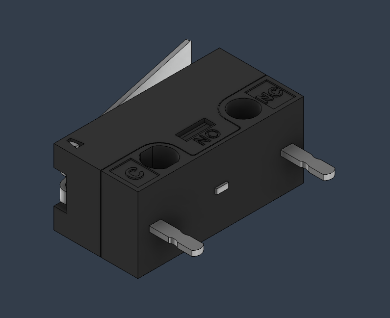
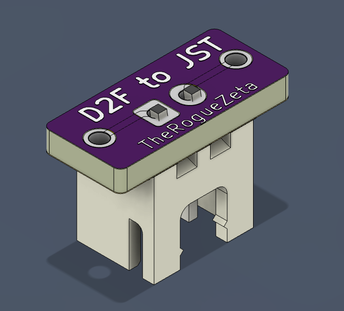
This is a PCB that adapts the Omron D2F family of micro switches to a standard JST 2 pin connector, making it easy to integrate mechanical switches into projects such as 3D printers or other electronics.
D2F to JST is an open-source printed circuit board by TheRogueZeta, from the TheRogueZeta/D2F_to_JST_PCB repository on GitHub, published under the GPL-3.0 licence. It is a 2-layer board of 12.8 × 6.4 mm with 2 parts on 2 nets, routed with 4 tracks and 0 vias.
Its parts include 1 connector and 1 switch.
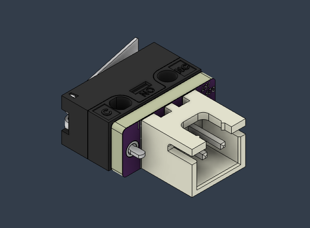
This is a PCB that adapts the Omron D2F family of micro switches to a standard JST 2 pin connector, making it easy to integrate mechanical switches into projects such as 3D printers or other electronics.
Boards are able to be ordered at OSHPark
See LICENSE for details.
| Qty | Value | Footprint | References |
|---|---|---|---|
| 1 | Conn_01x02_Pin | Connector_JST:JST_XH_B2B-XH-A_1x02_P2.50mm_Vertical | J1 |
| 1 | SW_SPDT | D2F:D2F | SW1 |
hzeller/rpi-rgb-led-matrix
Controlling up to three chains of 64x64, 32x32, 16x32 or similar RGB LED displays using Raspberry Pi GPIO


adamws/kicad-kbplacer
KiCad plugin for automatic keyboard's key placement and routing

Luos-io/luos_engine
Open-source and real-time orchestrator for cyber-physical-systems, to easily design, test and deploy embedded applications and digital twins.

NVNTLabs/switch2-SDEX2M2
Micro SD Express to M.2 NVME Adapter for Nintendo Switch 2

BlueSCSI/BlueSCSI-v2
BlueSCSI v2/Ultra - an open source, open hardware, SCSI emulator using the Pi Pico PR2040 and Pico 2 RP2350

ohmtech-rdi/eurorack-blocks
Software to Hardware Prototyping for Eurorack using C++, Max/Gen~ or Faust

It measures 12.8 × 6.4 mm and has 2 copper layers, 1.63 mm thick.
2 parts. The full list of its parts is on this page, with links to each part's symbol and footprint where PCBKit's library has them.
From the TheRogueZeta/D2F_to_JST_PCB repository on GitHub, at the commit this page was made from: the board is KiCAD/D2F to JST.kicad_pcb and its schematic KiCAD/D2F to JST.kicad_sch. PCBKit opens the board in the browser, with nothing to install.
Its repository publishes it under the GPL-3.0 licence: you may reuse it on that licence's terms (keep the author's notice, and for a copyleft licence share your changes alike).