2 layers102 × 84 mm
3D PrEBo
TheColonelYoung/3D_PREBO
3D printer expansion board. Add more fan controllers, TMC2130 wiring support, induction probe voltage convertor, LED lighting (supports WS1812).
79 partsCC-BY-SA-4.0

 TheColonelYoung/Arachne
Mainly 3D printed manipulator with 6 axis of freedom based on design of steward platform
Arachne is an open-source printed circuit board by TheColonelYoung, from the TheColonelYoung/Arachne repository on GitHub, published under the GPL-3.0 licence. It is a 2-layer board of 100 × 75 mm with 278 parts on 143 nets, routed with 2,996 tracks and 1,849 vias.
It is built around the L5973D, WS2818B and USBLC6-2SC6, with the SKL310, BAV99 and ESDA6V1-5SC6 among its other parts. Its parts include 99 capacitors, 77 diodes, 46 resistors, 13 ICs and 12 connectors. It belongs with the STM32 boards of this library.


Mainly 3D printed manipulator with 6 axis of freedom based on design of steward platform
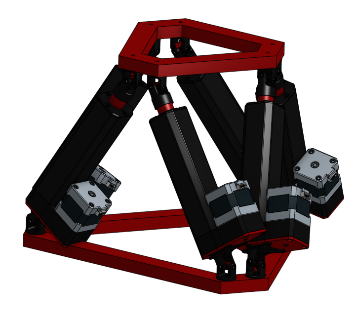
!!! Now the notes in this repository are rather assumptions that will need to be verified in practice !!!
Platform is based on two nearly triangular bases connected with 6 linear actuators.
Control of these actuators is driven from motherboard.
Lower base is stationary, upper base part is movable.
Motherboard is positioned in lower triangle base. Motherboard communicates with controller (pc) via serial line with G-code.
First version of platform is 3D printed. Next version are supposed to be from aluminium.
Motion system is based on affine transformation.
Basic system contains from seven points. Which are placed in center of platform and in points of connection with actuators.
Points are on both triangular bases. Corresponding points have same numbers.
Position of point is described as coordinates in cartesian system.
Center point is not used for calculation of motion, is used only as center point of mass.
Every point is represented as vector [x,y,z,1].
Distance between connect points of actuator on lower and upper bases is calculated.
Affine transformation is applied on all point of connection with actuators on upper base.
Now is calculated new distance between fixed and movable points. Difference between distances in old and new position is travel distance of actuator.
By repeating this process for every actuator is calculated one move of platform.
Rotation terms: Pitch(X), Roll(Y), Yaw(Z)
Speed scaling is linear based on travel distance of actuator.
Acceleration must grow proportionally as speed.
Traveled distance is integration of actual speed of motor by time.
Example: Two motor M1 - travels 10mm, M2 - travels 30mm,
Jams of platforms are possible when movement is not synchronized. In this state some motor can be in end-position, but motion is not done.
Main issue is when position of points in unknown. This happens when platform is powered on. Before power of platform must be homed -> this cannot be reliably secured.
Possible homing sequence is that all actuators will be moved with same speed to their home position. But there is possibility of jam.
This example is calculated only for one actuators, others have same calculations.
Platform is now at home position. So position of points describes offset from zero point.
Length of all actuator is same. Probably zero length of pushrods + length of body.
In this example is body length two times retractable length. Minimal length 30mm, maximal length is 50mm.
Length is calculated between mates connecting base and actuator.
Point on upper base ($P_{UP}$) is at [-2, 0, 0, 1], motions are shift forward (Y+2), and rotation to right(Z+90°).
Point on lower base ($P_{LOW}$) is at [-1, 2, -2.45, 1], Z offset is determinated by vertical distance between lower and upper base in home state.
Shift matrix:
$\begin{bmatrix}1 & 0 & 0 & X \0 & 1 & 0 & Y \ 0 & 0 & 1 & Z \ 0 & 0 & 0 & 1 \\end{bmatrix}$
Rotation matrix around Z - Yaw($\gamma$):
$\begin{bmatrix}\cos(\gamma) & -\sin(\gamma) & 0 & 0 \\sin(\gamma) & \cos(\gamma) & 0 & 0 \ 0 & 0 & 1 & 0 \ 0 & 0 & 0 & 1 \\end{bmatrix}$
Multiplication of matrix
Note: if platform is not home is necessary to make another translation of object from current position of center point to center of space. This is represented as empty translation-1 matrix
[Translation-1 * Rotation * Translation * Point]
New coordinates of $P_{UP}$ are [-2, -2, 0, 1]
Old distance between $P_{UP}$ and $P_{LOW}$ is: 3.317 cm
New distance between $P_{UP}$ and $P_{LOW}$ is: 4.796 cm
Difference between old and new length of actuator is: 1.479 cm
So actuator must change length to 4.796 cm, which is nearly maximal length (in this example).
Change of length is + 1.479 cm, speed and acceleration depends on motion of other actuators.
Linear actuators are connected with hexagonal platform with universal joint with can give joint freedom to move freely. Rotation of joint should not be constrained by joint but by length of arm (linear actuator length).
Joints consists of 3 parts. Two forks and one central block. X and Y axis of forks are perpendicular between forks (forks are turned against self by 90° on Z axis). Fork is connected to central block through small ball bearing. This ball bearing removed as much of friction as possible.
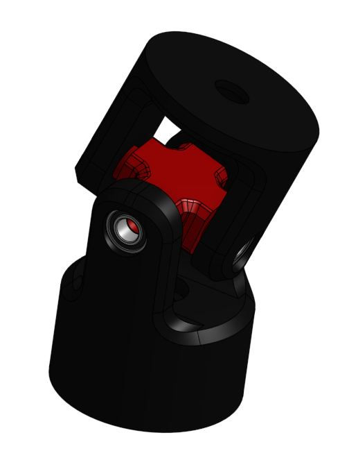
Universal joint
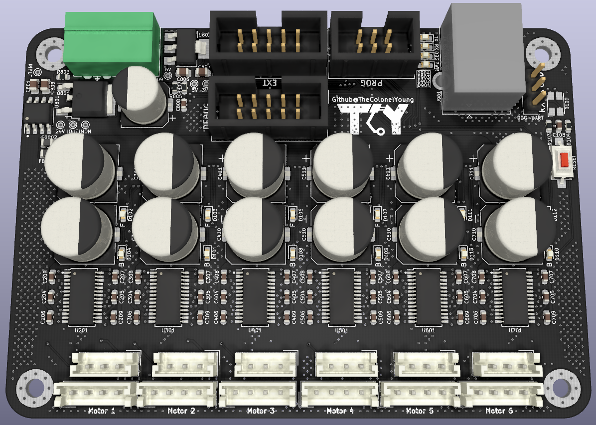
Main Motherboard contains six stepper motor drivers L6470 in TSSOP28 package.
PCB is designed with maximal dimensions of 10x7cm, so it can be cheaply manufactured.
| Qty | Value | Footprint | References |
|---|---|---|---|
| 49 | SKL310 | Diode_SMD:D_SOD-123F | D202, D203, D204, D205, D206, D207, D208, D209, D302, D303, D304, D305, D306, D307, D308, D309 +33 |
| 36 | 100nF/50V | Capacitor_SMD:C_0603_1608Metric | C204, C205, C206, C207, C208, C209, C304, C305, C306, C307, C308, C309, C404, C405, C406, C407 +20 |
| 17 | 100nF | Capacitor_SMD:C_0603_1608Metric | C101, C102, C103, C104, C105, C106, C107, C108, C213, C313, C413, C513, C613, C713, C804, C805 +1 |
| 14 | 100k | Resistor_SMD:R_0603_1608Metric | R103, R201, R202, R301, R302, R401, R402, R501, R502, R601, R602, R701, R702, R803 |
| 12 | 100uF/63V | Capacitor_SMD:CP_Elec_10x10 | C210, C211, C310, C311, C410, C411, C510, C511, C610, C611, C710, C711 |
| 12 | 47uF/6,3V | Capacitor_SMD:CP_Elec_5x5.3 | C202, C203, C302, C303, C402, C403, C502, C503, C602, C603, C702, C703 |
| 12 | LED | LED_SMD:LED_0603_1608Metric | D101, D102, D103, D104, D105, D106, D107, D108, D110, D111, D112, D113 |
| 7 | 10k | Resistor_SMD:R_0603_1608Metric | R104, R802, R804, R805, R806, R807, R810 |
| 6 | 10nF/50V | Capacitor_SMD:C_0603_1608Metric | C212, C312, C412, C512, C612, C712 |
| 6 | 1k | Resistor_SMD:R_0603_1608Metric | R205, R305, R405, R505, R605, R705 |
| 6 | 220nF/16V | Capacitor_SMD:C_0603_1608Metric | C201, C301, C401, C501, C601, C701 |
| 6 | 2k7 | Resistor_SMD:R_0603_1608Metric | R204, R304, R404, R504, R604, R704 |
| 6 | 560k | Resistor_SMD:R_0603_1608Metric | R203, R303, R403, R503, R603, R703 |
| 6 | BAV99 | Package_TO_SOT_SMD:SOT-23 | D201, D301, D401, D501, D601, D701 |
| 6 | L6470_HTSSOP28 | Package_SO:HTSSOP-28-1EP_4.4x9.7mm_P0.65mm_EP3.4x9.5mm_ThermalVias | U201, U301, U401, U501, U601, U701 |
| 6 | SW2 | Connector_JST:JST_EH_B3B-EH-A_1x03_P2.50mm_Vertical | J201, J301, J401, J501, J601, J701 |
| 6 | Stepper_Motor_bipolar | Connector_JST:JST_EH_B4B-EH-A_1x04_P2.50mm_Vertical | M201, M301, M401, M501, M601, M701 |
| 4 | 22R | Resistor_SMD:R_0603_1608Metric | R101, R102, R901, R902 |
| 4 | 4.7uF (X7R) | Capacitor_SMD:C_0805_2012Metric | C806, C807, C812, C813 |
| 4 | M3 | MountingHole:MountingHole_3.2mm_M3_Pad_Via | H101, H102, H103, H104 |
| 3 | 4x22R | Resistor_SMD:R_Array_Convex_4x0603 | RN101, RN102, RN103 |
| 2 | 1uF (X7R) | Capacitor_SMD:C_0805_2012Metric | C801, C803 |
| 2 | 22R@100MHz | Inductor_SMD:L_0805_2012Metric | FB801, FB802 |
| 2 | BLUE | LED_SMD:LED_0603_1608Metric_Castellated | D903, D904 |
| 2 | ESDA6V1-5SC6 | Package_DFN_QFN:ST_UQFN-6L_1.5x1.7mm_Pitch0.5mm | D114, D802 |
| 1 | 10uF 50V (ceramic) | Capacitor_SMD:C_2816_7142Metric_Pad3.20x4.45mm_HandSolder | C802 |
| 1 | 15uH | Inductor_SMD:L_Neosid_Ms85 | L801 |
| 1 | 180k | Resistor_SMD:R_0603_1608Metric | R801 |
| 1 | 1SMB5925 | Diode_SMD:D_SMB | D801 |
| 1 | 20k | Potentiometer_SMD:Potentiometer_Bourns_3214J_Horizontal | RV801 |
| 1 | 20k | Resistor_SMD:R_0603_1608Metric | R808 |
| 1 | 220nF | Capacitor_SMD:C_0603_1608Metric | C810 |
| 1 | 22nF | Capacitor_SMD:C_0603_1608Metric | C811 |
| 1 | 24V | TestPoint:TestPoint_THTPad_D1.0mm_Drill0.5mm | TP804 |
| 1 | 2A | Fuse:Fuse_1206_3216Metric | F801 |
| 1 | 300uF 16V | Capacitor_SMD:CP_Elec_8x10 | C809 |
| 1 | 3V3 | TestPoint:TestPoint_THTPad_D1.0mm_Drill0.5mm | TP808 |
| 1 | 4.7k | Resistor_SMD:R_0603_1608Metric | R809 |
| 1 | 50R@100MHz, 3A | Inductor_SMD:L_0805_2012Metric | L901 |
| 1 | 5V | TestPoint:TestPoint_THTPad_D1.0mm_Drill0.5mm | TP806 |
| 1 | 6V | TestPoint:TestPoint_THTPad_D1.0mm_Drill0.5mm | TP807 |
| 1 | 7V | Diode_SMD:D_SMB | D804 |
| 1 | ACS712xLCTR-20A | Package_SO:SOIC-8_3.9x4.9mm_P1.27mm | U801 |
| 1 | AOD4189 | Package_TO_SOT_SMD:TO-252-2 | Q801 |
| 1 | ASMB-MTB0-0A3A2 | LED_SMD:LED_Avago_PLCC4_3.2x2.8mm_CW | D109 |
| 1 | DBG_UART | Connector_PinHeader_2.54mm:PinHeader_1x03_P2.54mm_Vertical | J903 |
| 1 | Extension | Connector_IDC:IDC-Header_2x05_P2.54mm_Vertical | J102 |
| 1 | GREEN | LED_SMD:LED_0603_1608Metric_Castellated | D901 |
| 1 | I_DIV | TestPoint:TestPoint_THTPad_D1.0mm_Drill0.5mm | TP805 |
| 1 | I_MAIN | TestPoint:TestPoint_THTPad_D1.0mm_Drill0.5mm | TP803 |
| 1 | L5973D | Package_SO:HSOP-8-1EP_3.9x4.9mm_P1.27mm_EP2.41x3.1mm_ThermalVias | U803 |
| 1 | LOGO | TCY_logo:TCY_LOGO_13x6mm | G*** |
| 1 | LOGO | TCY_logo:TCY_QR_12x12 | G*** |
| 1 | NCP1117-3.3_SOT223 | Package_TO_SOT_SMD:SOT-223-3_TabPin2 | U804 |
| 1 | NCP1117-5.0_SOT223 | Package_TO_SOT_SMD:SOT-223-3_TabPin2 | U802 |
| 1 | PROG_CONN_STM_6p | Connector_IDC:IDC-Header_2x03_P2.54mm_Vertical | J902 |
| 1 | PWR_IN | TestPoint:TestPoint_THTPad_D1.0mm_Drill0.5mm | TP801 |
| 1 | R_Pack04 | Resistor_SMD:R_Array_Convex_4x0603 | RN901 |
| 1 | STM32L452CEUx | Package_DFN_QFN:QFN-48-1EP_7x7mm_P0.5mm_EP5.15x5.15mm_ThermalVias | U101 |
| 1 | STPS340U | Diode_SMD:D_SMB | D805 |
| 1 | SW_Push | Button_Switch_SMD:SW_SPST_CK_RS282G05A3 | SW101 |
| 1 | Salae_logic | Connector_IDC:IDC-Header_2x05_P2.54mm_Vertical | J101 |
| 1 | USBLC6-2SC6 | Package_TO_SOT_SMD:SOT-23-6 | U901 |
| 1 | USB_B | Connector_USB:USB_B_OST_USB-B1HSxx_Horizontal | J901 |
| 1 | V_IN | Connector_Phoenix_MC:PhoenixContact_MC_1,5_4-G-3.5_1x04_P3.50mm_Horizontal | J801 |
| 1 | WS2818B | Package_SO:SOP-8_3.76x4.96mm_P1.27mm | U102 |
| 1 | YELLOW | LED_SMD:LED_0603_1608Metric_Castellated | D902 |
TheColonelYoung/3D_PREBO
3D printer expansion board. Add more fan controllers, TMC2130 wiring support, induction probe voltage convertor, LED lighting (supports WS1812).

punkfab/pcb-corpus
235 real KiCad boards from open-source hardware repositories, prepared as a placement and routing benchmark

CRImier/MyKiCad
My KiCad boards. Can't be bothered uploading individually anymore, so here you go.

TheColonelYoung/NCL30160_Demo
Demonstration board for light control IC NCL30160.

electrodyssey/lboard2
experimental Spartan-6 sound processing board with XC6SLX9-TQG144 and TLV320AIC3204


hackclub/OnBoard
💡 Join 1,000 teenagers and make your first PCB with a $100 grant!

It measures 100 × 75 mm and has 2 copper layers, 1.6 mm thick.
278 parts, built around the L5973D, WS2818B, USBLC6-2SC6 and SKL310. The full list of its parts is on this page, with links to each part's symbol and footprint where PCBKit's library has them.
From the TheColonelYoung/Arachne repository on GitHub, at the commit this page was made from: the board is PCB/Arachne.kicad_pcb and its schematic PCB/Arachne.kicad_sch. PCBKit opens the board in the browser, with nothing to install.
Its repository publishes it under the GPL-3.0 licence: you may reuse it on that licence's terms (keep the author's notice, and for a copyleft licence share your changes alike).