
2 layers56 × 65 mm
SeaTalk1
dotnet/iot
This repo includes .NET Core implementations for various IoT boards, chips, displays and PCBs.
24 parts2.4kMIT

Hello!\ This is a name card I made for me to wear at hackathons and events.\ It has 6 leds, 6 Buttons, and a Buzzer, all powered on a CR2032 Cell Battery.
Solder is an open-source printed circuit board by Taran-the-Idiot, from the Taran-the-Idiot/Name-Card repository on GitHub, published under the MIT licence. It is a 2-layer board of 80 × 40 mm with 24 parts on 17 nets, routed with 86 tracks and 42 vias.
Its parts include 7 resistors, 6 diodes and 6 switches.
Hello!
This is a name card I made for me to wear at hackathons and events.
It has 6 leds, 6 Buttons, and a Buzzer, all powered on a CR2032 Cell Battery.
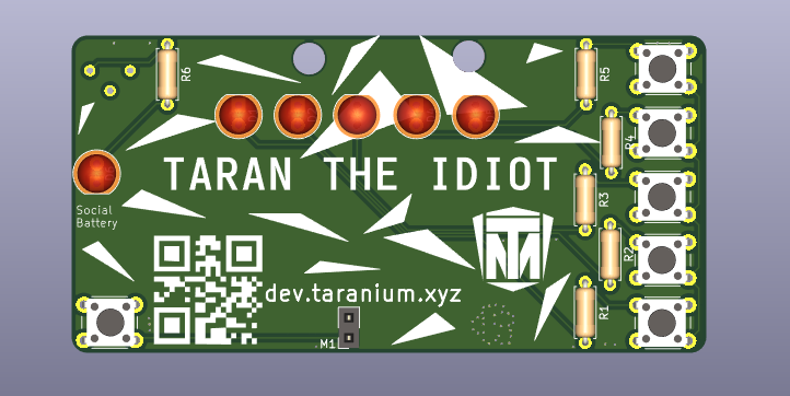
This is a nametag that clips onto your shirt with a safety pin.
It has 5 LEDs that turn on through buttons on the right and a buzzer that turns on through the button on the left.
The 6th LED is to express my social battery as it depreciates throughout the day.
All of this runs on a 3V CR2032 cell battery
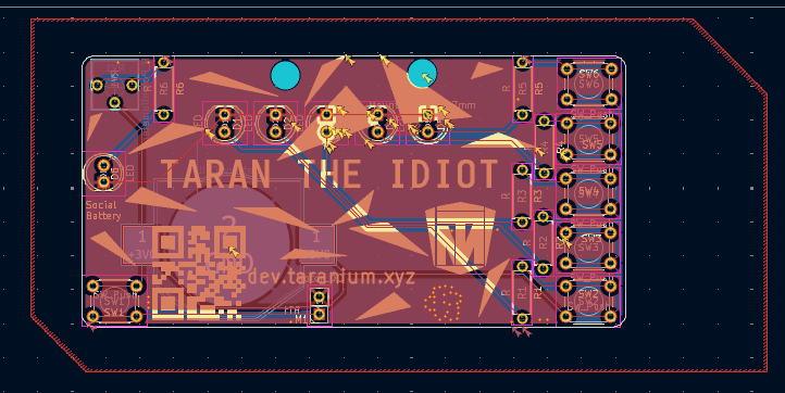

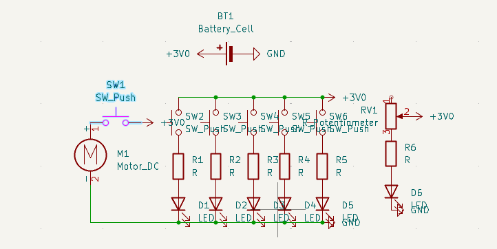
Go to any pcb maker and give them the production files.
Order The parts and solder them onto the pcb
Yay you did it.
OPTIONAL: You can edit the pcb files and personalise it a bit
6 LEDs(Various colours)
6 6mm Buttons
7 220 Ohm Resistors
1 CR2032 Battery Holder
1 Poteniometer
1 CR2032 Battery
1 Buzzer
1 PCB
Made By @Taran The Idiot from Hack Club
| Qty | Value | Footprint | References |
|---|---|---|---|
| 7 | R | Resistor_THT:R_Axial_DIN0207_L6.3mm_D2.5mm_P7.62mm_Horizontal | R1, R2, R3, R4, R5, R6, R7 |
| 6 | LED | LED_THT:LED_D5.0mm | D1, D2, D3, D4, D5, D6 |
| 6 | SW_Push | Button_Switch_THT:SW_PUSH_6mm | SW1, SW2, SW3, SW4, SW5, SW6 |
| 1 | |||
| 1 | Battery_Cell | Battery:BatteryHolder_Keystone_3002_1x2032 | BT1 |
| 1 | Buzzer | Buzzer_Beeper:Indicator_PUI_AI-1440-TWT-24V-2-R | BZ1 |
| 1 | R_Potentiometer | Potentiometer_THT:Potentiometer_Vishay_T73YP_Vertical | RV1 |
The 23 most common of 24 parts.
dotnet/iot
This repo includes .NET Core implementations for various IoT boards, chips, displays and PCBs.

pascallanger/DIY-Multiprotocol-TX-Module
Multiprotocol TX Module (or MULTI-Module) is a 2.4GHz transmitter module which controls many different receivers and models.


rusefi/rusefi
rusefi - GPL internal combustion engine control unit

DraftShift/StealthChanger
Tool changing system for Vorons and other front mount printer motion systems, not just stealthburner.

VoronDesign/Voron-Hardware
Cool Hardware designed by the Voron Design group

hackclub/OnBoard
💡 Join 1,000 teenagers and make your first PCB with a $100 grant!

It measures 80 × 40 mm and has 2 copper layers, 1.6 mm thick.
24 parts. The full list of its parts is on this page, with links to each part's symbol and footprint where PCBKit's library has them.
From the Taran-the-Idiot/Name-Card repository on GitHub, at the commit this page was made from: the board is PCB/Solder.kicad_pcb and its schematic PCB/Solder.kicad_sch. PCBKit opens the board in the browser, with nothing to install.
Its repository publishes it under the MIT licence: you may reuse it on that licence's terms (keep the author's notice, and for a copyleft licence share your changes alike).