4 layers90 × 100 mm

 TUO4742/SeedlingRobot
Full-stack ROS2 automatic seedling clamping robot covering mechanical, hardware, STM32/FreeRTOS and motion control.
WLKJ2025011CAR MOTOR V1.2 is an open-source printed circuit board by TUO4742, from the TUO4742/SeedlingRobot repository on GitHub. It is a 4-layer board of 85 × 56 mm with 96 parts on 116 nets, routed with 387 tracks and 159 vias.
It is built around the M2.5, KH-6X6X5H-STM and DC-044A-A200, with the SK-22F02-G060 and TYPE-C-16PIN-0 among its other parts. Its parts include 31 capacitors, 20 resistors, 19 connectors, 8 ICs and 5 diodes. It belongs with the robots and motor control boards and the 8051 (CH55x, STC, AT89) boards of this library.


一套面向自动取苗 → 运输 → 放苗作业的全栈移动机器人:从机械结构、自制 PCB、STM32/FreeRTOS 固件, 到 ROS2 导航与定位,全部由本人完成。
起源于 2026 睿抗机器人开发者大赛(CAIR 工程竞技赛道),赛后将工程整理为可复现的开源版本。
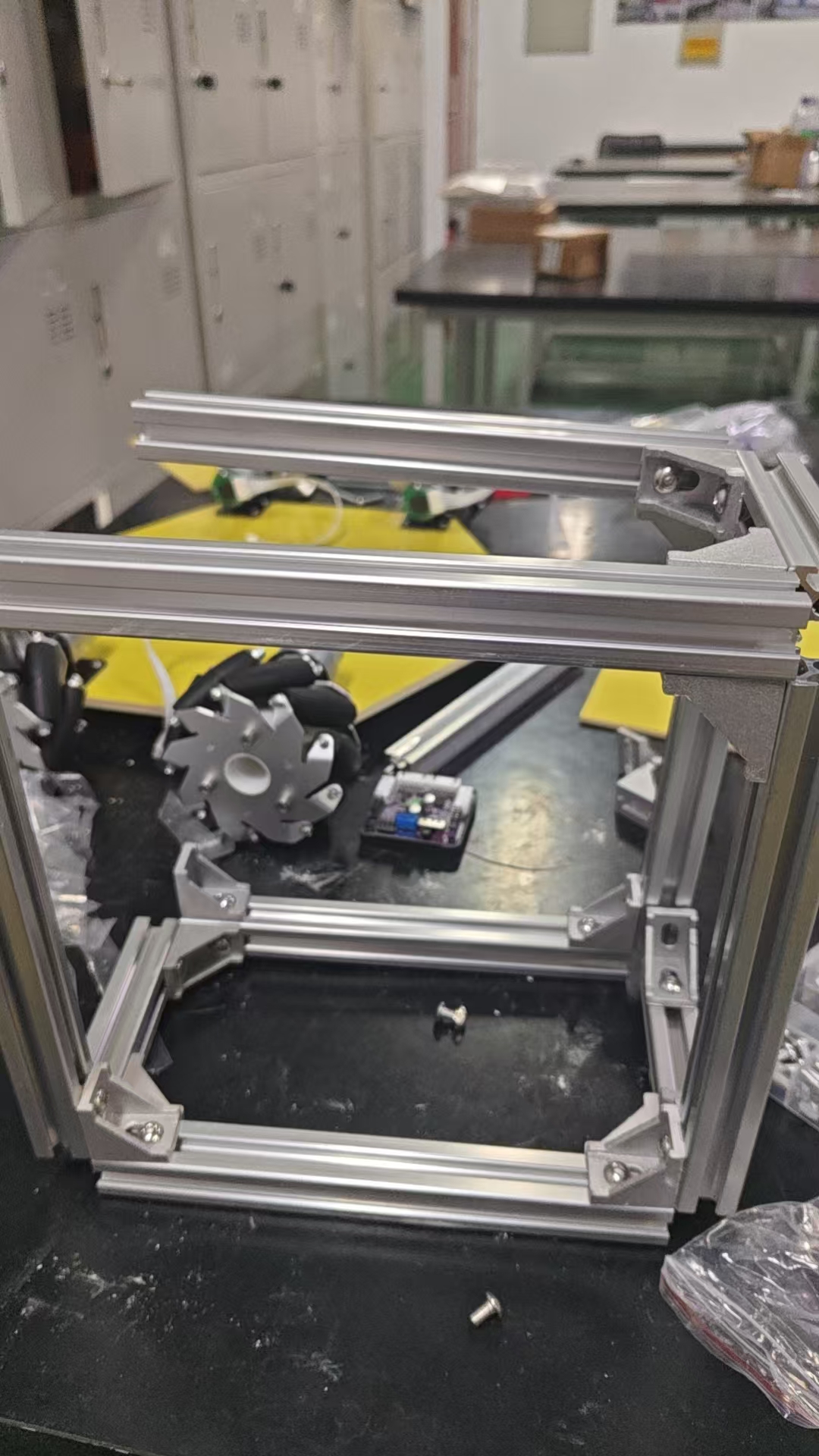
演示视频:docs/media/automatic-seedling-clamping-demo.mp4
| 能力 | 实现位置 | 状态 |
|---|---|---|
| 麦克纳姆四轮全向移动(前后 / 横移 / 斜行 / 原地旋转) | firmware/stm32/Robot/chassis_task.c | 实机验证 |
| 四路编码器测速 + 增量式 PID 闭环 | firmware/stm32/Headware/encoder.c | 实机验证 |
| 四舵机取苗 / 夹苗 / 放苗姿态与缓动 | firmware/stm32/Robot/arm_control.c | 实机验证 |
| PS2 手柄遥控 + 组合键机械臂点动 | firmware/stm32/Headware/ps2_usart5.c | 实机验证 |
| 300 ms 失联停车、短刹、模式互锁、回中解锁 | firmware/stm32/Robot/chassis_task.c | 实机验证 |
| ROS2 导航(AMCL + NavFn + MPPI 全向) | ros2_ws/ | 代码完成,待实机联调 |
        ┌──────────────────────────────┐
        │  ROS2 (Ubuntu / RDK)          │
        │  chassis_node → /odom → EKF   │
        │  Nav2: AMCL + NavFn + MPPI    │
        └──────────────┬───────────────┘
                       │ UART 14B 下行 / 22B 上行
                       ▼
        ┌──────────────────────────────┐
        │  STM32F103RCT6 + FreeRTOS     │
        │  ┌────────────┬─────────────┐ │
        │  │ 底盘控制    │ 机械臂/舵机  │ │
        │  │ 逆解 + PID  │ 姿态 + 缓动  │ │
        │  └────────────┴─────────────┘ │
        │  安全:失联停车 / 模式互锁      │
        └──────────────┬───────────────┘
                       ▼
TB6612 ×2 · 编码器 ×4 · 舵机 ×4固件里只有 2 个 FreeRTOS 任务:
| 任务 | 优先级 | 栈 | 周期 | 作用 |
|---|---|---|---|---|
defaultTask | Normal | 512 B | 1 ms | CubeMX 生成的占位空任务 |
chassisTask | High | 4 KB | 20 ms | 唯一的业务主循环 |
chassisTask 在单个循环里串行完成:手柄帧解析 → 三级安全互锁 → 机械臂输入 → 麦轮逆解 → 编码器闭环 → 舵机输出。
刻意不使用队列 / 信号量 / 互斥量,中断与任务之间用 volatile 标志 + 单行双缓冲 + __disable_irq 临界区通信。
理由是控制链路本身是严格顺序的,引入跨任务 IPC 只会增加调度抖动,对 20 ms 周期没有收益。
真正的时间基准由 TIM6 中断(50 Hz) 提供,
vTaskDelayUntil保证任务周期无累积漂移。
轮序 0=FL, 1=RR, 2=RL, 3=FR(物理接线 remap 后的顺序,不是 FL/FR/RL/RR),
K = L + W = 0.168 m,轮径 0.065 m。
逆解(chassis_task.c)
FL = vx - vy - K·wz      RR = vx - vy + K·wz
RL = vx + vy - K·wz FR = vx + vy + K·wz正解(encoder.c)
vx = ( FL + RR + RL + FR) / 4
vy = (-FL - RR + RL + FR) / 4
wz = (-FL + RR - RL + FR) / (4K)两个方向严格互逆,已验证误差 < 1e-15(见第 8 节自检工具)。
定时器资源受限,四路舵机用两种方式驱动:
时基统一为 TIM5 @ 1 MHz,周期 20 ms(50 Hz),脉宽 500 + angle × 2000 / 180 µs,
限幅 0–180°,缓动步进 2°/20 ms(约 100 °/s)。
ros2_ws/ 是按本机实际参数重写的,不是从别的项目复制。详见
ros2_ws/README.md 与 docs/ROS2导航设计与验证.md。
| 环节 | 选型 |
|---|---|
| 底盘桥接 | 自研 seedling_chassis(C++,50 Hz) |
| 里程计 | 四轮编码器正解 → 积分 → /odom |
| 融合 | robot_localization EKF(无 IMU,仅轮速) |
| 定位 | AMCL OmniMotionModel(麦轮必须) |
| 规划 | NavFn / Dijkstra |
| 控制 | RotationShim + MPPI motion_model: Omni |
| 限速 | vx 0.35 / vy 0.30 / wz 0.80 |
两个麦轮专属坑已避开:
OmniMotionModel → 横移会被当成噪声;velocity_smoother.max_velocity 第二项留空 → 横移在输出前被截成 0。firmware/stm32/ STM32F103RCT6 + FreeRTOS 固件(Keil MDK)
Robot/ 底盘任务、机械臂状态机、麦轮逆解
Headware/ 电机 / 编码器 / 舵机 / PS2 / I2C 驱动
Doc/ 接线说明、ROS2 接口说明
ros2_ws/ ROS2 导航栈(底盘桥接 + Nav2 参数 + URDF)
hardware/ 自制控制板 KiCad 工程
mechanical/ 四自由度平行夹爪与整车的 STEP / STL / DXF
docs/ 媒体素材与设计文档1. Keil MDK 打开 firmware/stm32/MDK-ARM/1_template_led.uvprojx
2. 确认时钟 72 MHz、TIM5 舵机时基、TIM2 PWM、编码器定时器
3. 编译并烧录 STM32F103RCT6
4. 上电前核对:电机方向、舵机零位、急停、通信波特率cd ros2_ws
source /opt/ros/humble/setup.bash
colcon build --symlink-install
source install/setup.bash
# 建图
ros2 launch seedling_bringup slam.launch.py
# 导航(需先有地图)
ros2 launch seedling_bringup nav2.launch.py map:=/path/to/map.yaml接入导航前需要给固件补一组二进制串口帧,见
firmware/stm32/Doc/ROS2接口说明.md。
python3 ros2_ws/tools/kinematics_check.py    # 正解/逆解闭环、符号语义、分辨率
python3 ros2_ws/tools/protocol_selftest.py   # 14B/22B 帧编解码与校验
两者均为纯 Python,无第三方依赖,退出码 0 表示通过。
vy_max 已收敛到 0.30 m/s,不要盲目调高。stm32f1xx_hal_conf.h 中 IWDG/WWDG 宏被注释,长期无人值守运行需自行补上。while(1)。ros_bridge.c,打通 14/22 字节串口协议/odom 尺度与 AMCL 定位精度imu0 融合本项目自研代码采用 MIT License,见 LICENSE。
仓库中的 Drivers/(ST HAL + CMSIS)与 Middlewares/(FreeRTOS)为第三方组件,
遵循其原始许可条款,不受本项目 MIT 许可覆盖。
A full-stack ROS2 mecanum mobile robot for automatic seedling clamping: mechanical design, custom PCB,
STM32/FreeRTOS firmware (20 ms control loop, 4-wheel incremental PID, 4-servo actuation, lost-link safety),
and a ROS2 navigation stack (encoder odometry → robot_localization EKF → AMCL OmniMotionModel → NavFn → MPPI Omni).
Kinematics and the serial protocol ship with self-checking scripts. Firmware is field-proven;
the ROS2 navigation layer is implemented and statically verified but not yet validated on hardware.
| Qty | Value | Footprint | References |
|---|---|---|---|
| 11 | 100nF/50V/0603 | WIT_Capacitor_SMD:C_0603_1608Metric | C2, C3, C4, C9, C11, C12, C17, C19, C24, C26, C27 |
| 7 | 10K/1%/0603 | WIT_Resustor_SMD:R_0603_1608Metric | R1, R4, R6, R9, R10, R11, R16 |
| 6 | 2.54排针/3PIN/直插 | Connector_PinHeader_2.54mm:PinHeader_1x03_P2.54mm_Vertical | J9, J11, J12, J14, J15, J16 |
| 4 | 100K/1%/0603 | WIT_Resustor_SMD:R_0603_1608Metric | R3, R7, R17, R20 |
| 4 | 10uF/10V/0603 | WIT_Capacitor_SMD:C_0603_1608Metric | C20, C21, C29, C30 |
| 4 | 10uF/50V/1206 | Capacitor_SMD:C_1206_3216Metric | C5, C6, C13, C14 |
| 4 | 22uF/25V/1206 | Capacitor_SMD:C_1206_3216Metric | C7, C8, C15, C16 |
| 4 | M2.5 | MountingHole:MountingHole_2.7mm_M2.5 | H1, H2, H3, H4 |
| 4 | PH2.0/6PIN/直插 | Connector_JST:JST_PH_B6B-PH-K_1x06_P2.00mm_Vertical | J1, J2, J3, J4 |
| 3 | 100uF/25V/D6.3xL7 | Capacitor_THT:CP_Radial_D6.3mm_P2.50mm | C1, C18, C23 |
| 3 | 1K/1%/0603 | WIT_Resustor_SMD:R_0603_1608Metric | R2, R14, R18 |
| 3 | 2.2uF/25V/0603 | WIT_Capacitor_SMD:C_0603_1608Metric | C10, C22, C31 |
| 3 | 4.7K/1%/0603 | WIT_Resustor_SMD:R_0603_1608Metric | R12, R13, R15 |
| 3 | 翠绿色/0603 | LED_SMD:LED_0603_1608Metric | D2, D3, D4 |
| 2 | 1uF/25V/0603 | WIT_Capacitor_SMD:C_0603_1608Metric | C25, C28 |
| 2 | 2.54排母/22PIN/直插 | Connector_PinSocket_2.54mm:PinSocket_1x22_P2.54mm_Vertical | J7, J8 |
| 2 | 5.6uH/6A/0630/FXL0630-5R6-M | WIT_Inductr:L_Changjiang_FXL0630 | L1, L2 |
| 2 | KH-6X6X5H-STM | WIT_Button_Switch_SMD:SW_PUSH_6x6 | SW2, SW3 |
| 2 | SY8286ARAC/QFN20-3x3 | Package_DFN_QFN:QFN-20-1EP_3x3mm_P0.45mm_EP1.6x1.6mm | U1, U3 |
| 2 | TB6612FNG/SSOP-24 | Package_SO:SSOP-24_5.3x8.2mm_P0.65mm | U2, U5 |
| 2 | XH2.54/4PIN/直插 | Connector_JST:JST_XH_B4B-XH-A_1x04_P2.50mm_Vertical | J10, J13 |
| 1 | 0.01R/1%/1W/W1206 | Resistor_SMD:R_1206_3216Metric | R19 |
| 1 | 13K/1%/0603 | WIT_Resustor_SMD:R_0603_1608Metric | R8 |
| 1 | 1N5819WS/SOD323 | Diode_SMD:D_SOD-323_HandSoldering | D1 |
| 1 | 2.54排针/2x4PIN/直插 | Connector_PinHeader_2.54mm:PinHeader_2x04_P2.54mm_Vertical | J18 |
| 1 | 2N7002/SOT23-3 | Package_TO_SOT_SMD:SOT-23 | Q1 |
| 1 | 8.66K/1%/0603 | WIT_Resustor_SMD:R_0603_1608Metric | R5 |
| 1 | CH559T/SSOP-20 | Package_SO:SSOP-20_5.3x7.2mm_P0.65mm | U6 |
| 1 | DC-044A-A200 | WIT_Connector_BarrelJack:BarrelJack_CUI_PJ-079BH_Horizontal | J6 |
| 1 | IP2723T/QFN24-4x4 | Package_DFN_QFN:QFN-24-1EP_4x4mm_P0.5mm_EP2.5x2.5mm | U8 |
| 1 | KF301-5.0-2P/P5.0mm | TerminalBlock_Phoenix:TerminalBlock_Phoenix_MKDS-1,5-2_1x02_P5.00mm_Horizontal | J5 |
| 1 | LOGO | WIT_LOGO:WIT_20x8 | G*** |
| 1 | ME6206A33XG/SOT23-3 | Package_TO_SOT_SMD:TSOT-23 | U4 |
| 1 | NCEP3040Q/DFN8-3.3x3.3 | Package_SON:VSON-8_3.3x3.3mm_P0.65mm_NexFET | Q2 |
| 1 | QMB-09B-03/D9mmH5.5mm | WIT_Buzzer:Buzzer_D9_H5.5_P5 | BZ1 |
| 1 | SK-22F02-G060 | WIT_Switch:SK-22F02 | SW1 |
| 1 | SMAJ12A/SMA | Diode_SMD:D_SMA | D5 |
| 1 | TYPE-C16PIN/卧插 | Connector_USB:USB_C_Receptacle_GCT_USB4105-xx-A_16P_TopMnt_Horizontal | J19 |
| 1 | USBA/10.0 QHHTZB6.3 | WIT_USB:USB_A_TH_10x6.8mm_Horizontal | J17 |
| 1 | W25Q32JVSSIQ/SOP-8 | Package_SO:SOIC-8_5.23x5.23mm_P1.27mm | U7 |


guthmanny/feahi_rp2350
Soran SP-1 sampler firmware (RP2350 + ESP32-C6) and CBI-40 hardware

Digital-Naturalism-Laboratories/Mothbox_Electronics
This is where the electronics for the Mothbox are developed, such as the PCB! It's copied over from https://github.com/Digital-Naturalism-Laboratories/Mothbox/tree/main/Hardware/PCB so you can check that out if you want…


Diode663/ESP32_4-20mA_Sensor
Single-channel industrial 4-20 mA current-loop reader for ESPHome / Home Assistant. ESP32-S3 + INA226, USB-C powered, 24 V loop supply with a constant-current limiter. KiCad 10, generated from Python.

emaneric/Electronic-Christmas-Card
A christmas card made from a PCB with a STM32, LED display, buttons, and buzzer.

It measures 85 × 56 mm and has 4 copper layers, 1.6 mm thick.
96 parts, built around the M2.5, KH-6X6X5H-STM, DC-044A-A200 and SK-22F02-G060. The full list of its parts is on this page, with links to each part's symbol and footprint where PCBKit's library has them.
From the TUO4742/SeedlingRobot repository on GitHub, at the commit this page was made from: the board is hardware/睿抗-摘苗机器人pcb/WLKJ2025011CAR-MOTOR-V1.2.kicad_pcb and its schematic hardware/睿抗-摘苗机器人pcb/WLKJ2025011CAR-MOTOR-V1.2.kicad_sch. PCBKit opens the board in the browser, with nothing to install.
Its repository states no licence, so its author keeps all rights: ask TUO4742 before reusing the design.