
2 layers18.5 × 11.1 mm
Switch
byrantech/laptop
anyon_e, a highly integrated, high end, open source laptop. Attempt the impossible.
6 parts4.3kMIT

 TUDA-MUST/AcoustiFly2
AcoustiFly, a single transducer Acoustic Levitator
ULHolder is an open-source printed circuit board by TUDA-MUST, from the TUDA-MUST/AcoustiFly repository on GitHub, published under the GPL-3.0 licence. It is a 2-layer board of 31 × 10 mm with 6 parts on 2 nets, routed with 8 tracks and 0 vias.



Unlock the Power of Sound: Explore Acoustic Levitation with Ease and Precision. This project focuses on the development of an acoustic levitator, a fascinating technology capable of suspending small objects in mid-air using ultrasonic waves. It is:
This repository provides all the necessary resources, including code, schematics, and documentation, to build and experiment with your very own acoustic levitation system.
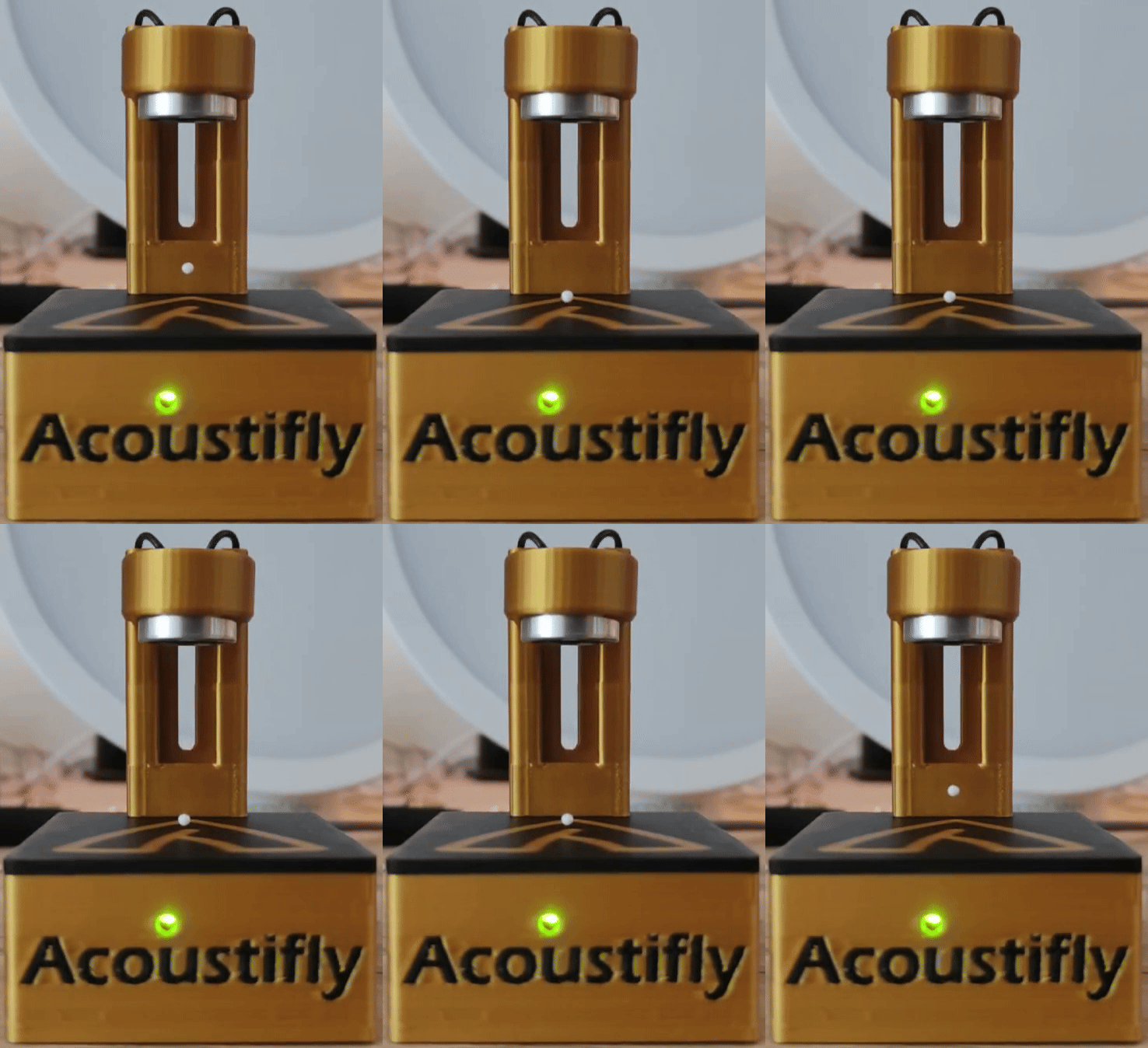
Our repository is dedicated to showcasing a method of acoustic levitation using a single transducer and a reflector. Acoustic levitation, also known as acoustic trapping, is a fascinating technique that allows objects to float in mid-air using sound waves.
In our approach, we utilize a single transducer, which emits high-frequency sound waves, and a carefully designed reflector. The transducer generates an acoustic field that interacts with the reflector to create standing waves within a confined region. These standing waves produce regions of high and low pressure, forming what is known as an "acoustic pressure node".
When an object is placed at a specific position within the acoustic pressure node, the forces exerted by the surrounding sound waves counteract the gravitational force, resulting in levitation. By precisely adjusting the distance of the transducer and the reflector, we can control the levitation height and stability of objects.
This unique approach offers several advantages. Firstly, it simplifies the setup by using only a single transducer and a reflector, reducing complexity and cost. Secondly, it enables precise control over the levitation process, allowing for manipulation and positioning of objects with great accuracy. Lastly, it opens up possibilities for various applications, including material handling, microfluidics, and scientific experiments.
In our repository, we provide detailed documentation, source code, and demonstrations to help you understand and implement this acoustic levitation technique. Whether you are a researcher, teacher, hobbyist, or enthusiast, we invite you to explore our repository, contribute to its development, and unlock the potential of acoustic levitation with a single transducer and a reflector.
Join us on this exciting journey of harnessing the power of sound waves to defy gravity. Visit our homepage to delve into our research and learn more about our team.
To assemble the Acoustifly you will need the following components:
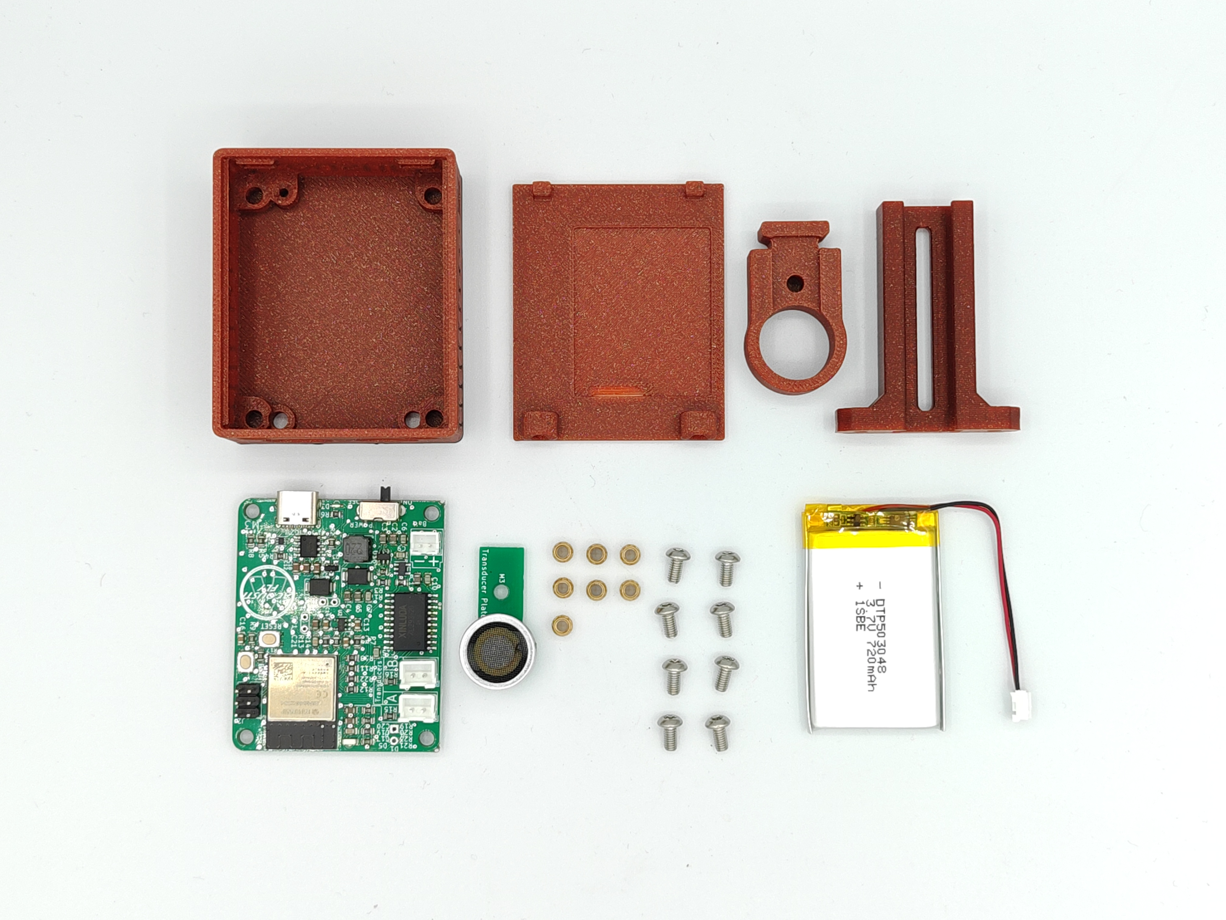
3D-printed:
Base, Battery-Cover, Transducer-Holder, Vertical profile
Electrical Components:
UT-1640K-TT-2-R Transducer, Transducer PCB, Acoustifly PCB, EXP-T11-020 3.7V 720mAh Lithium Polymer Battery with JST-PH connector,
Others:
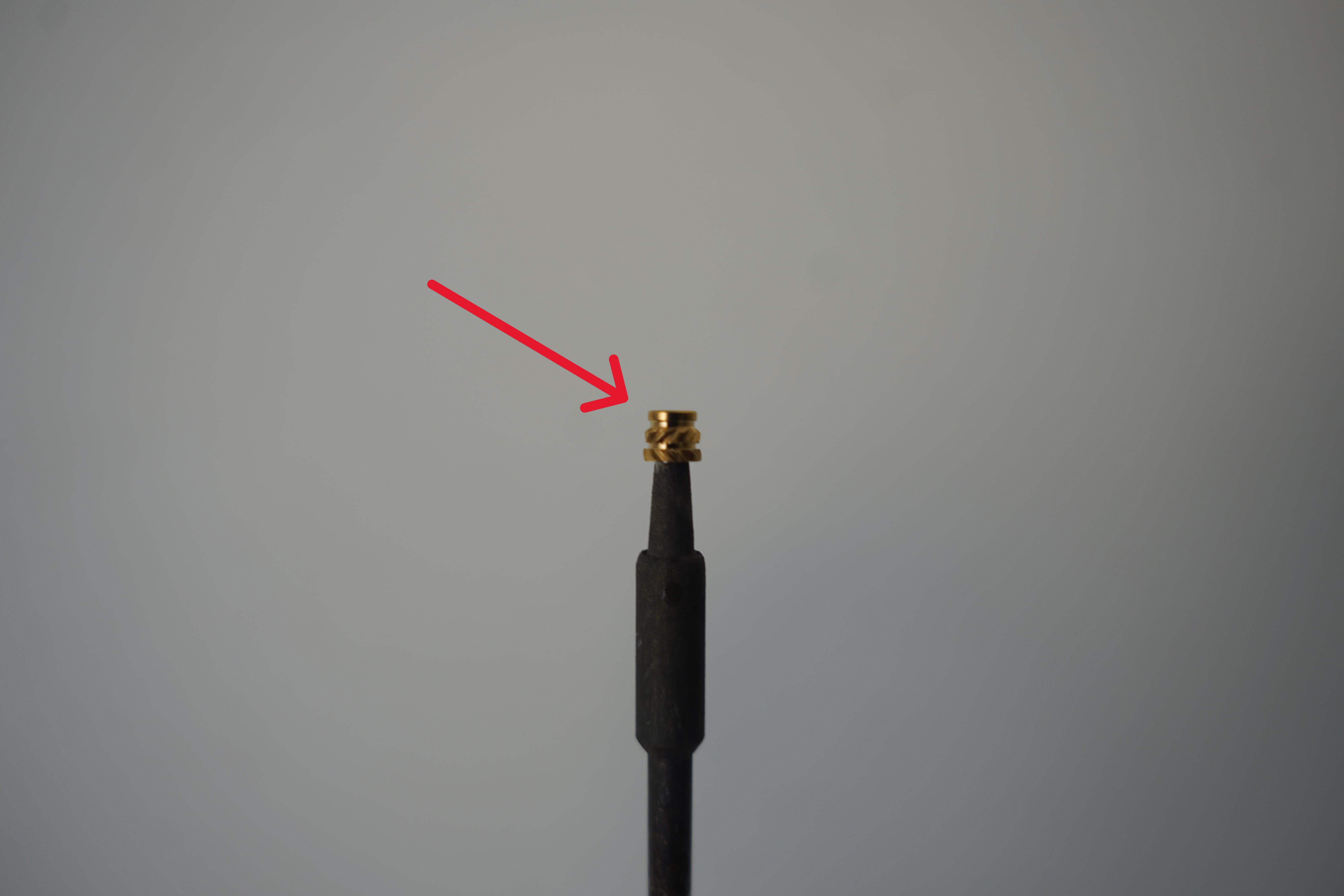
Ruthex M3s threaded inserts, M3 screws
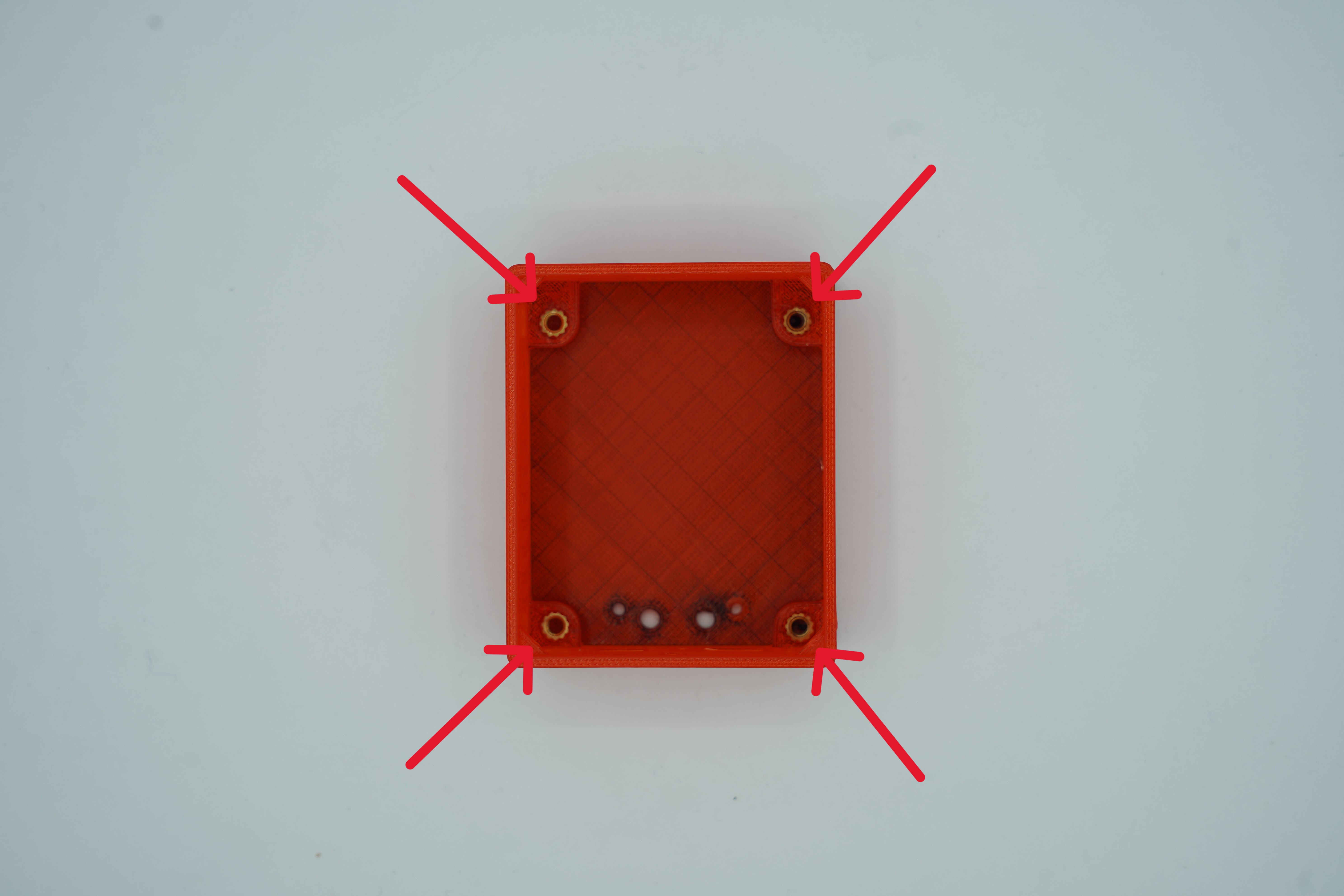
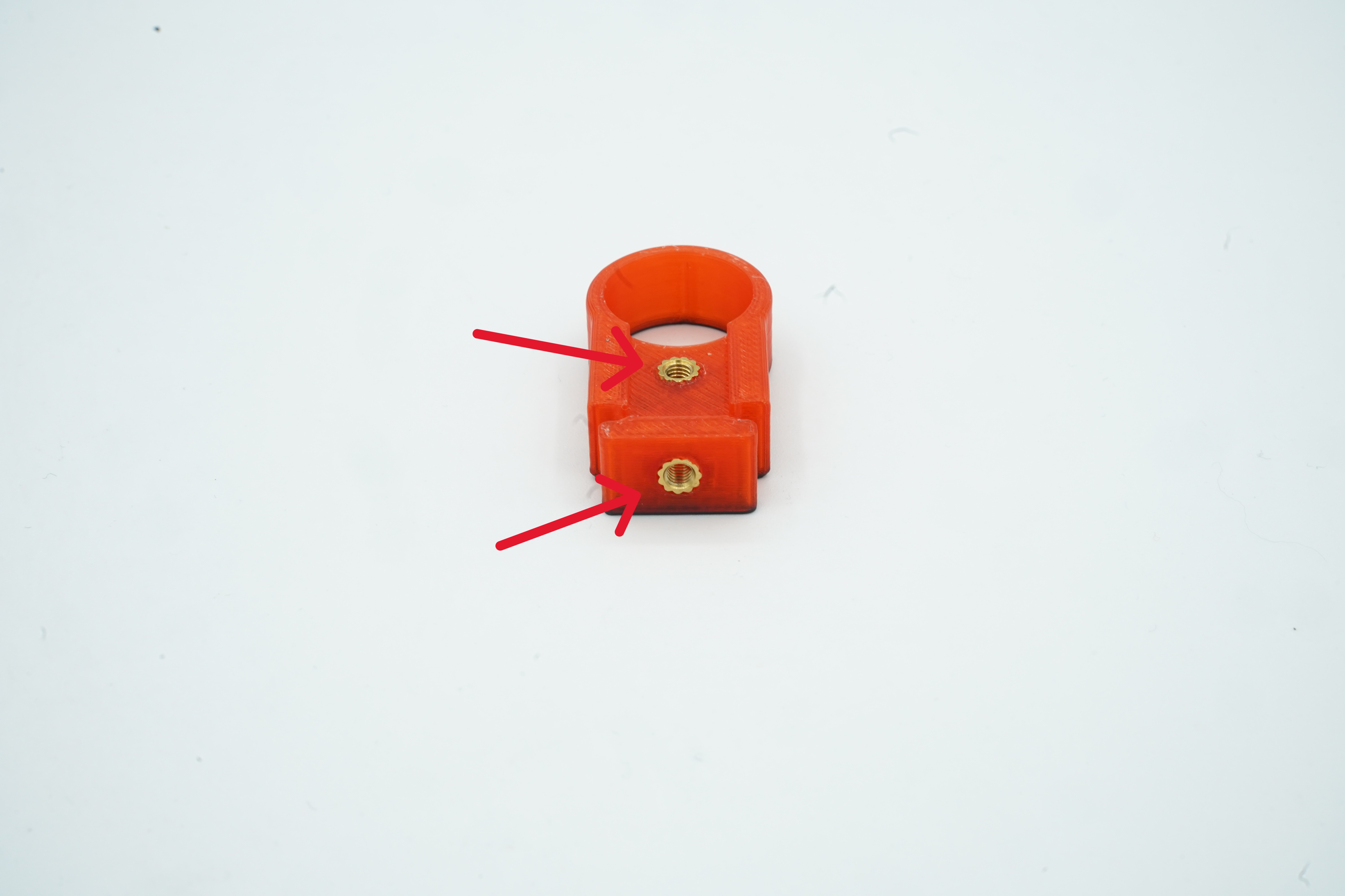
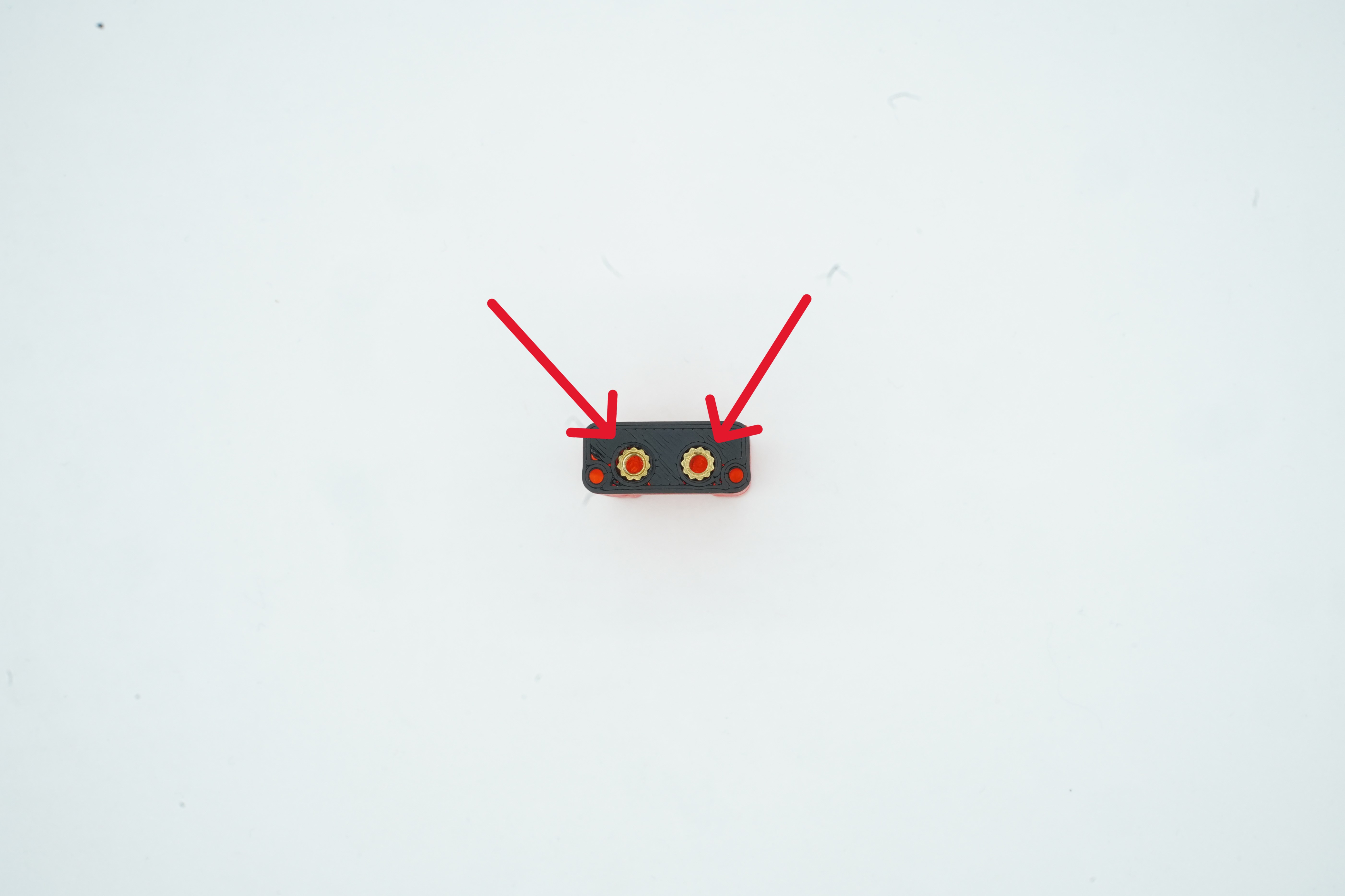
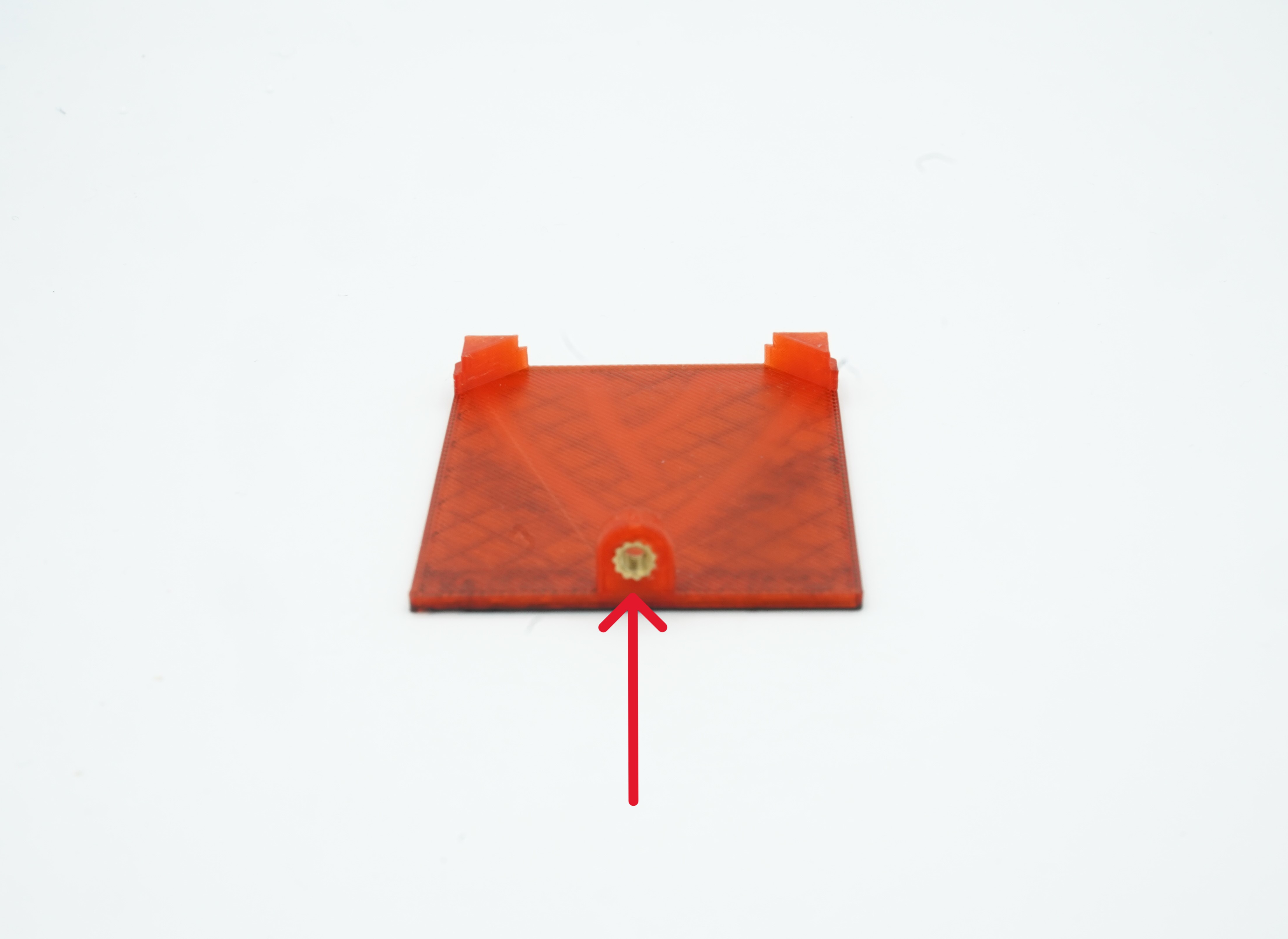
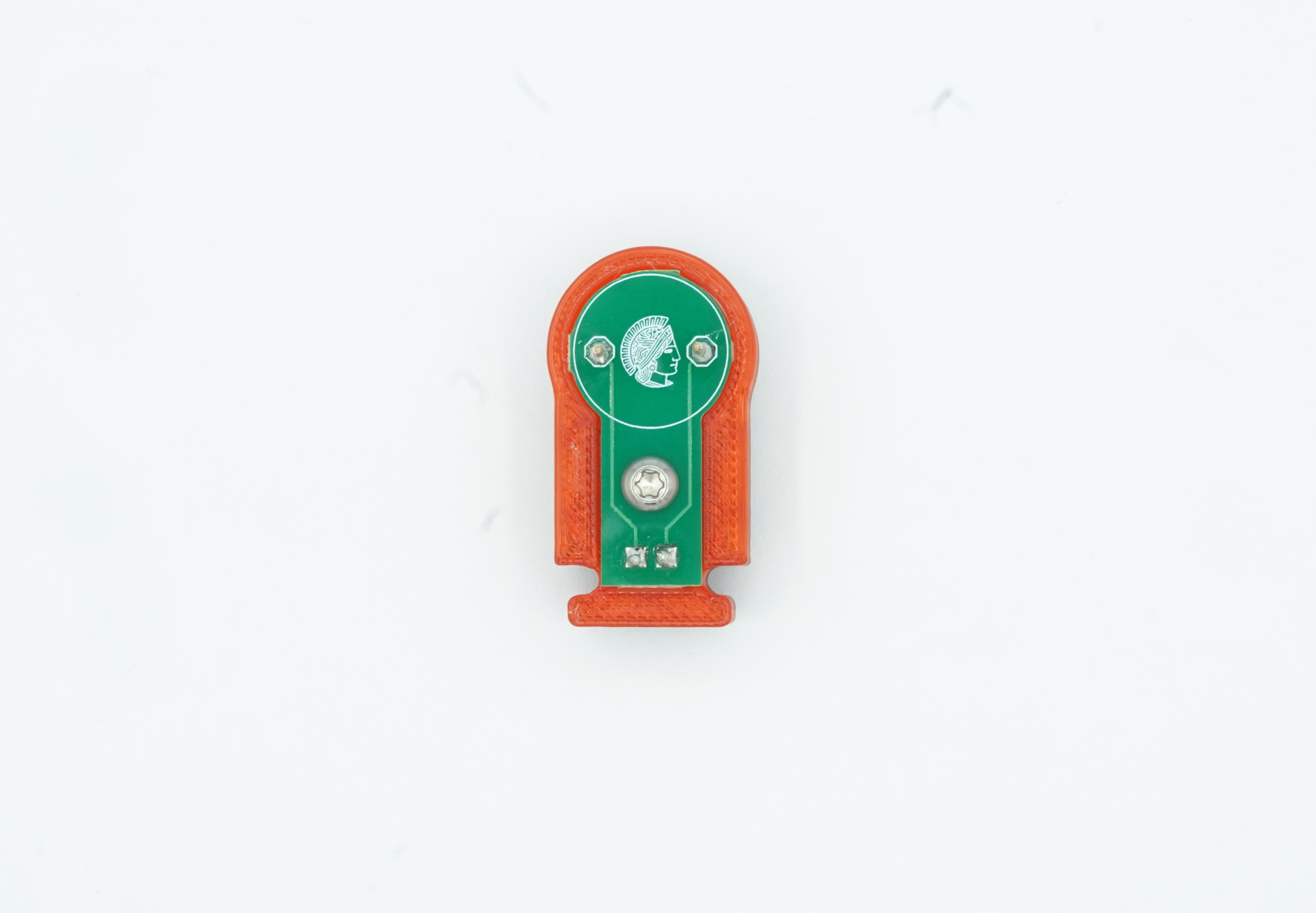
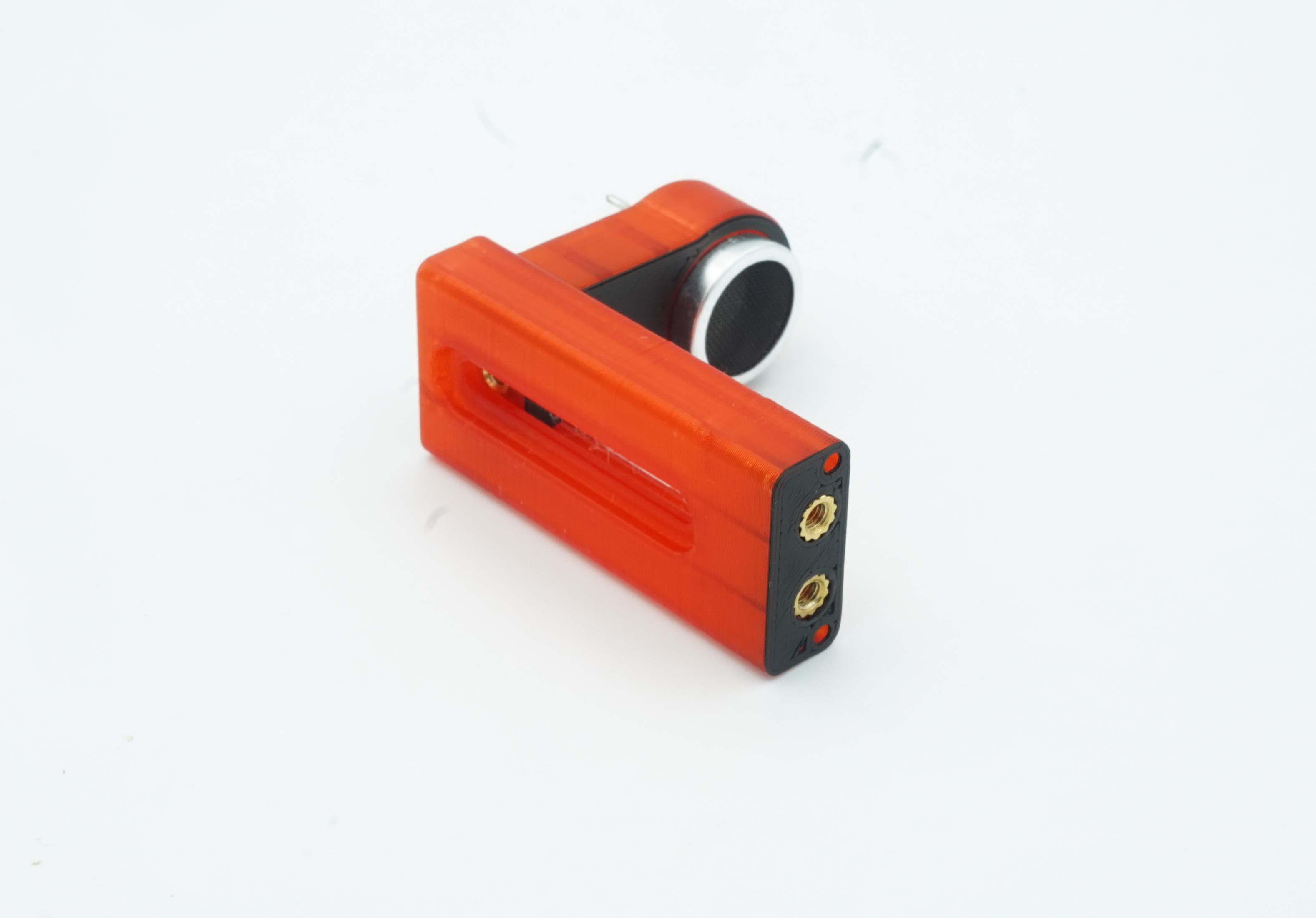
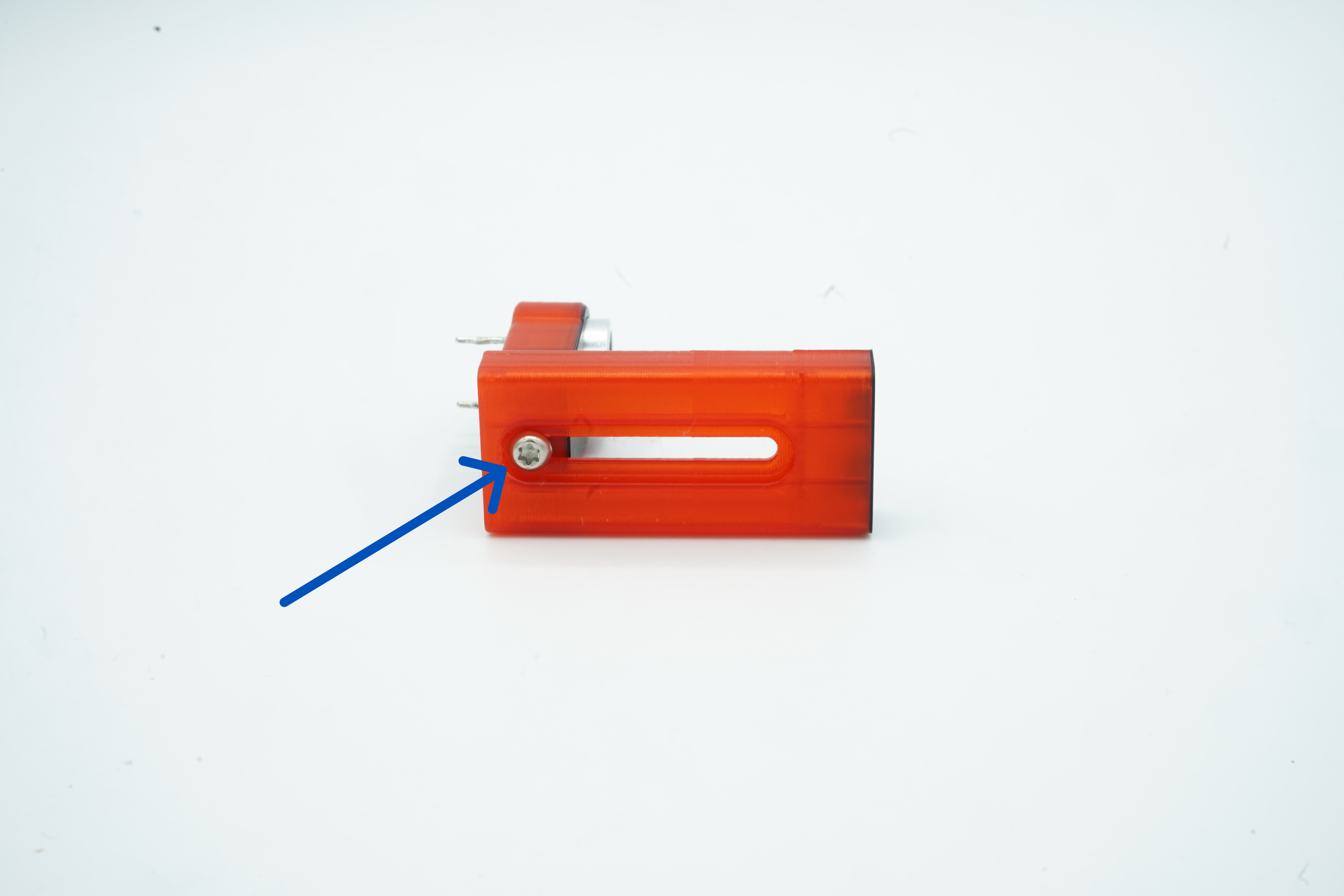
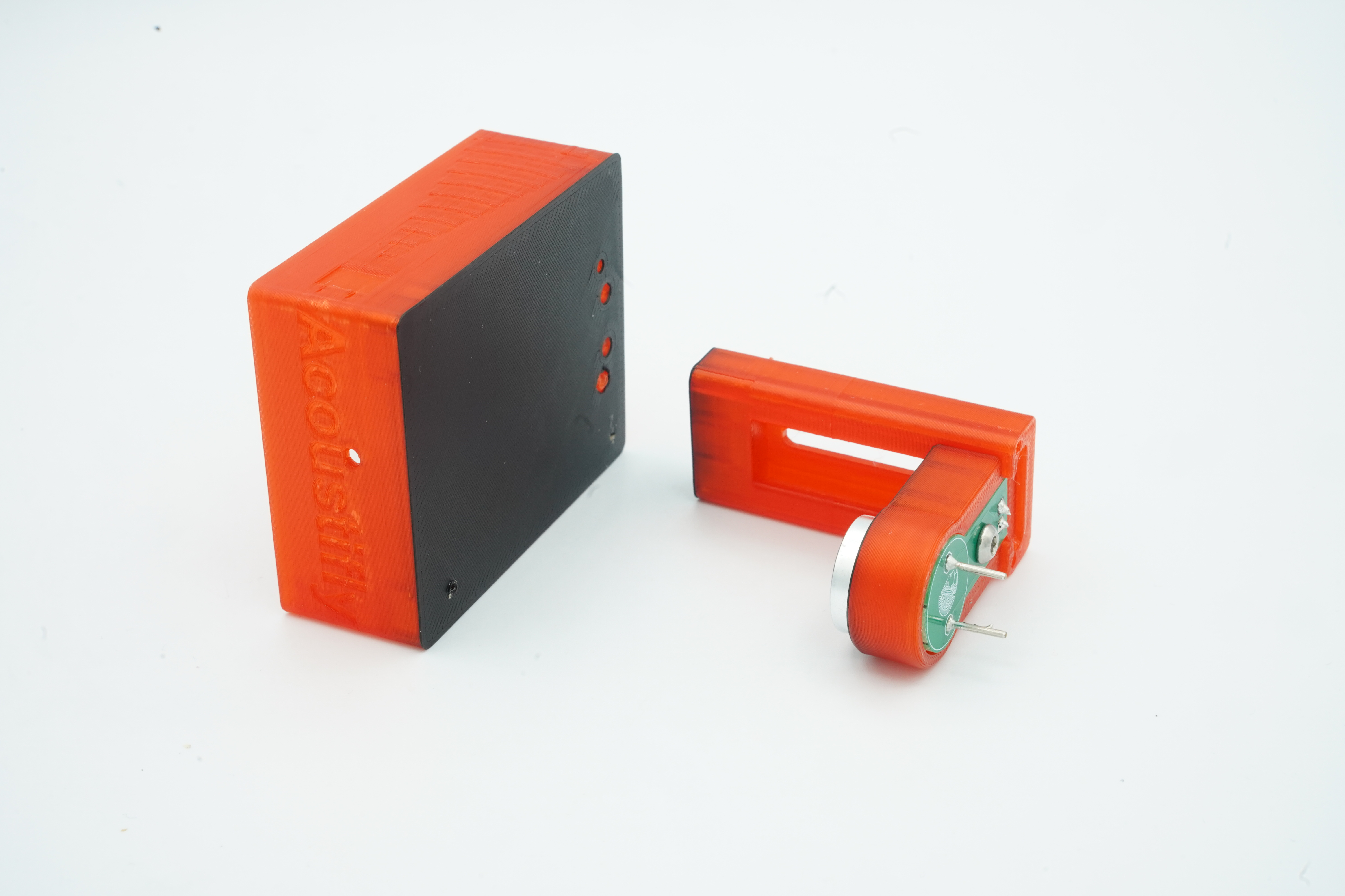
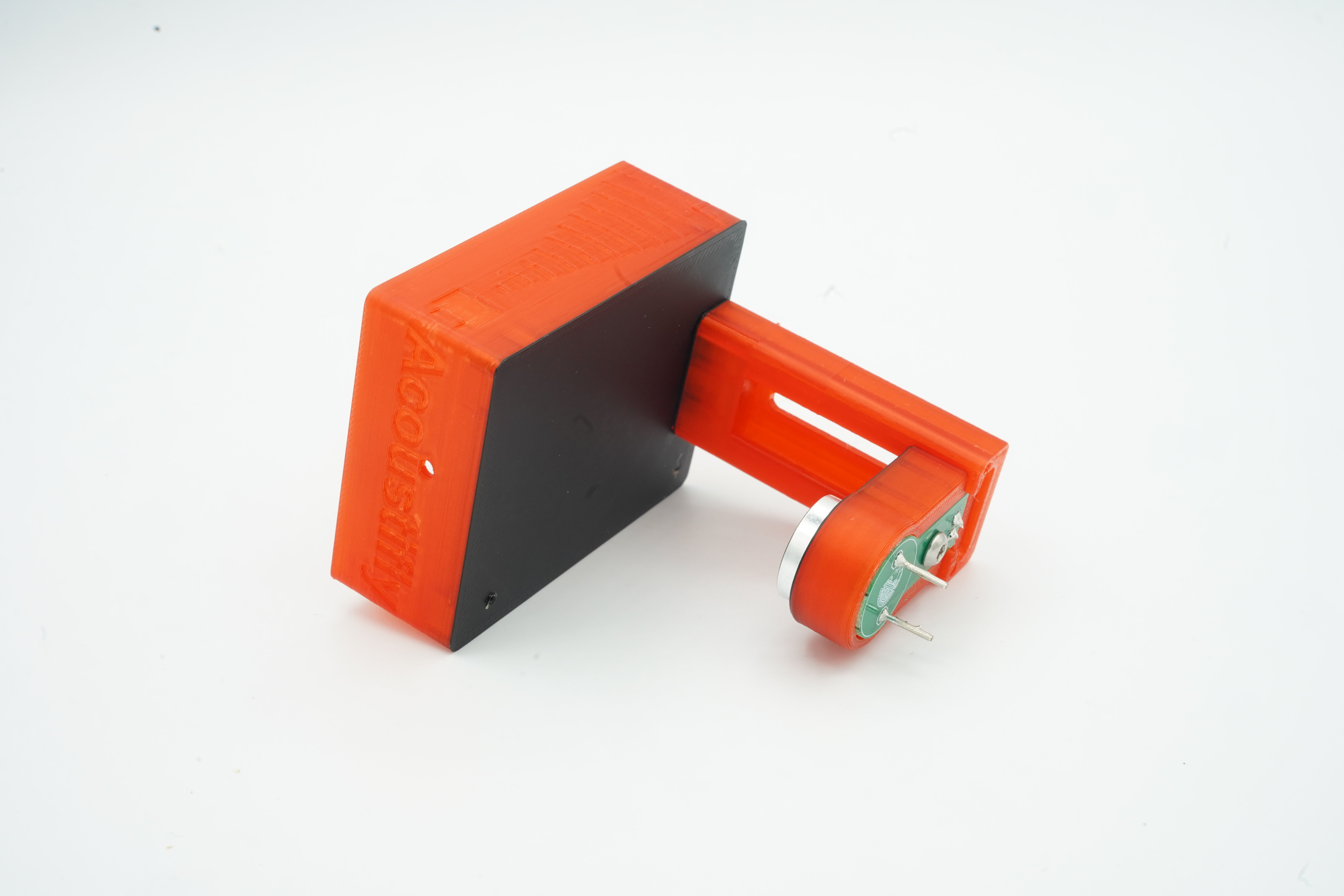
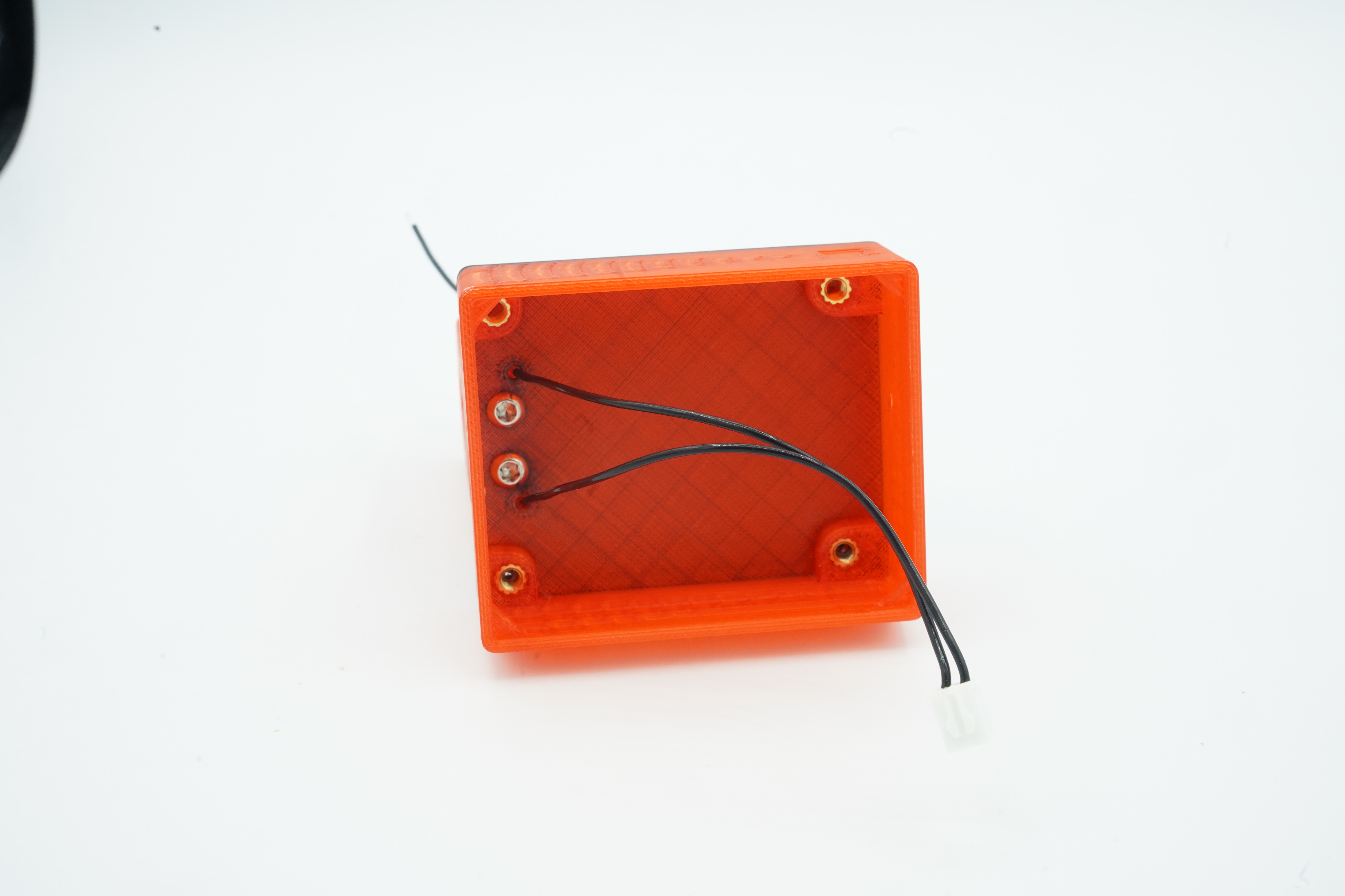
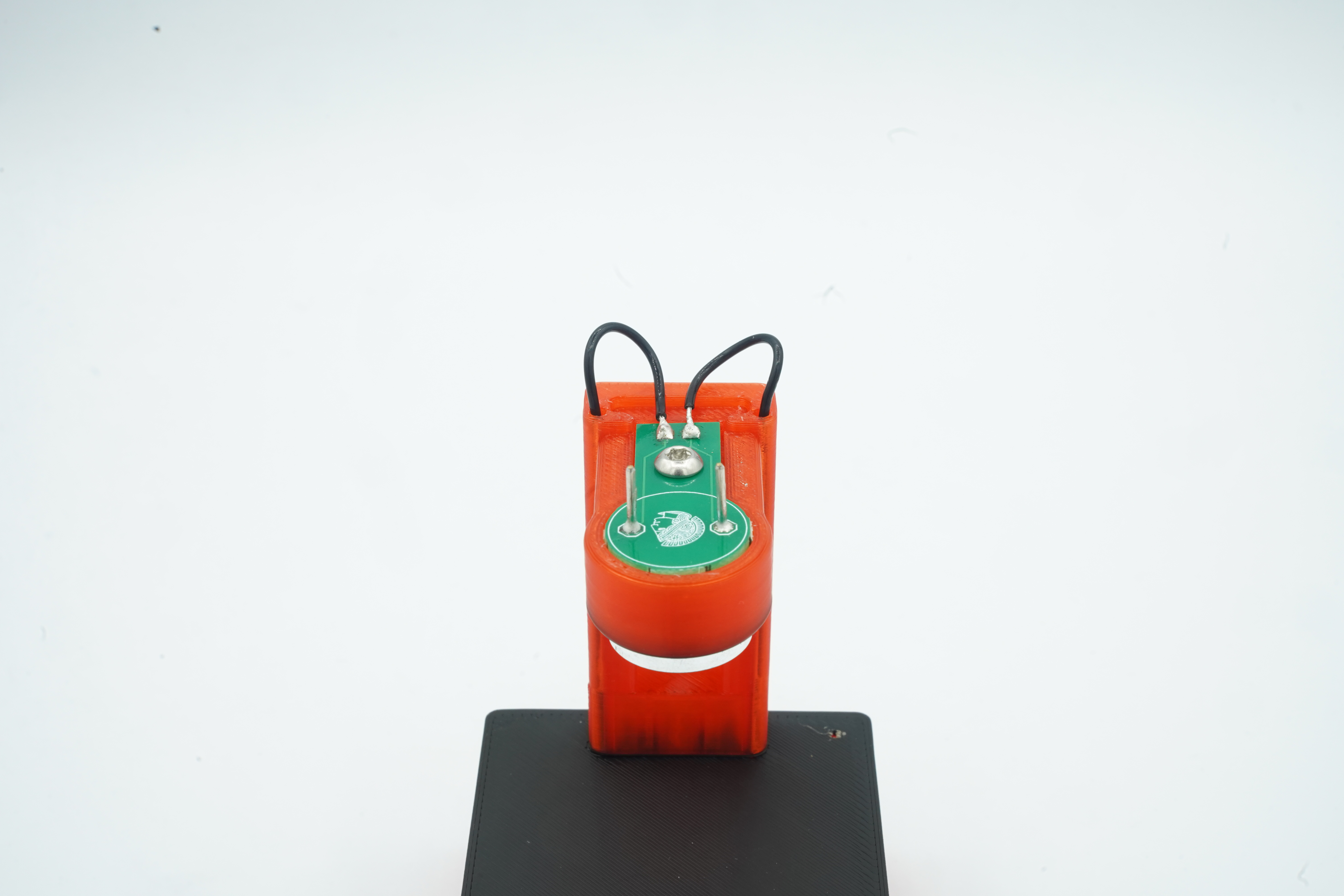
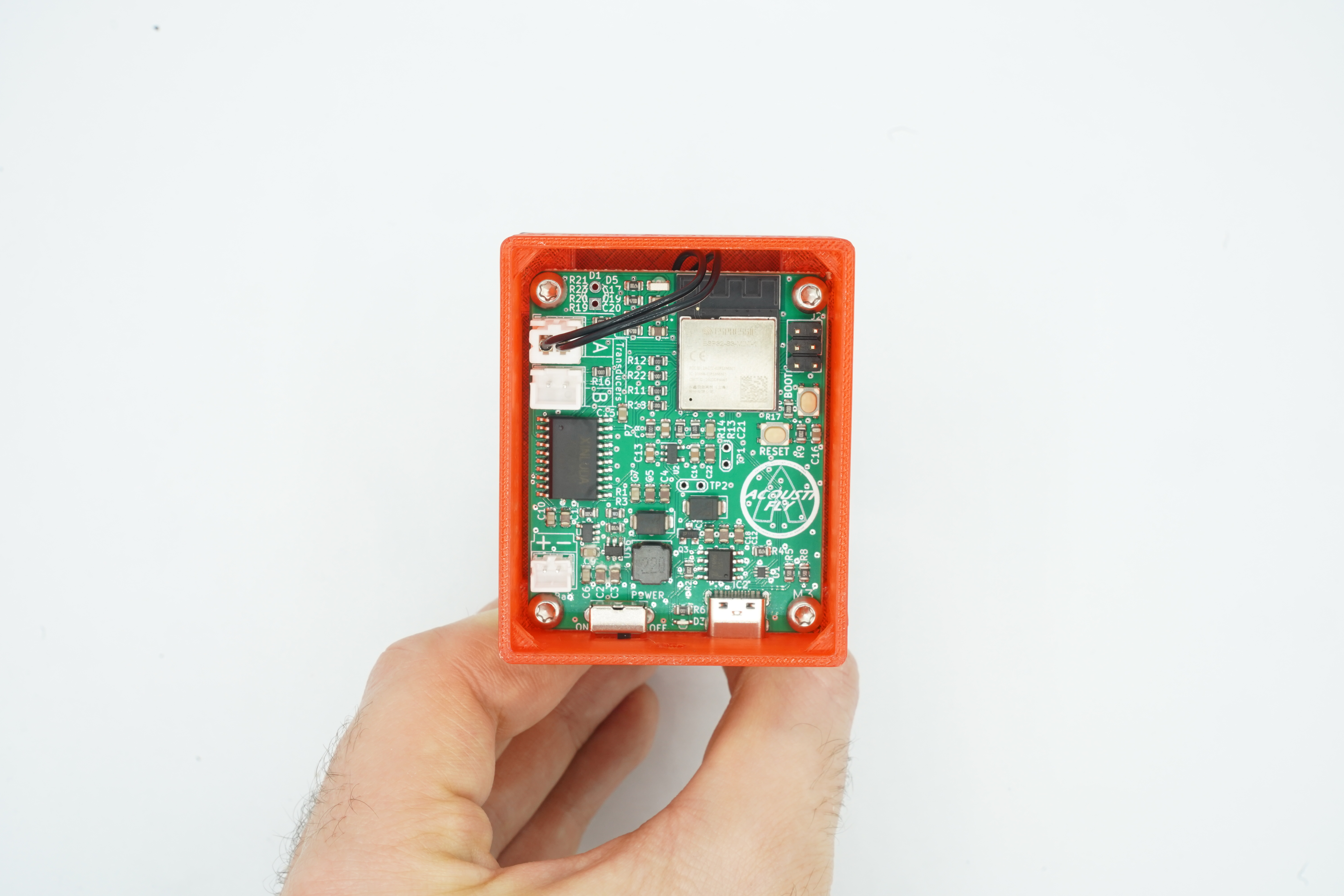
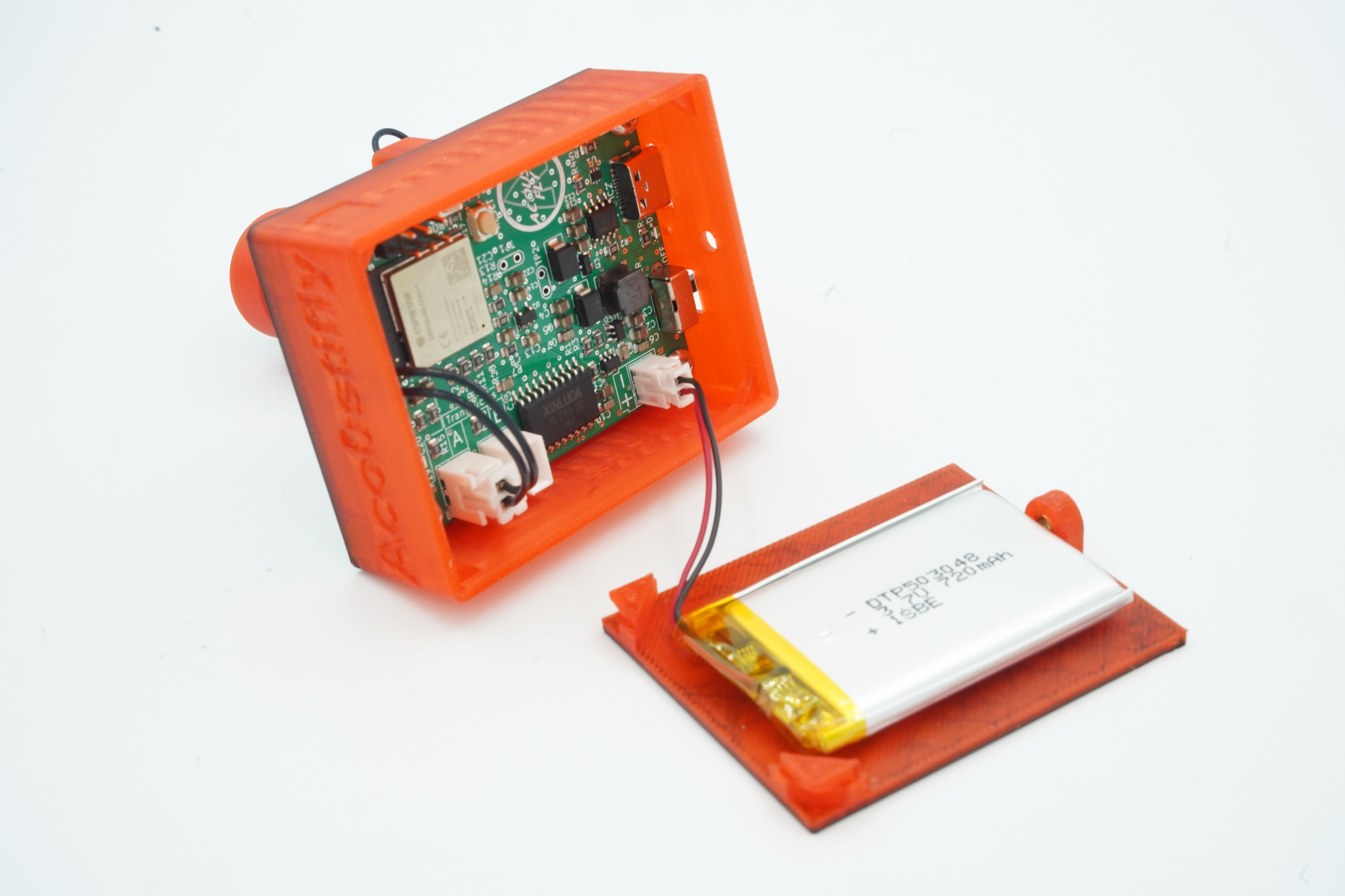
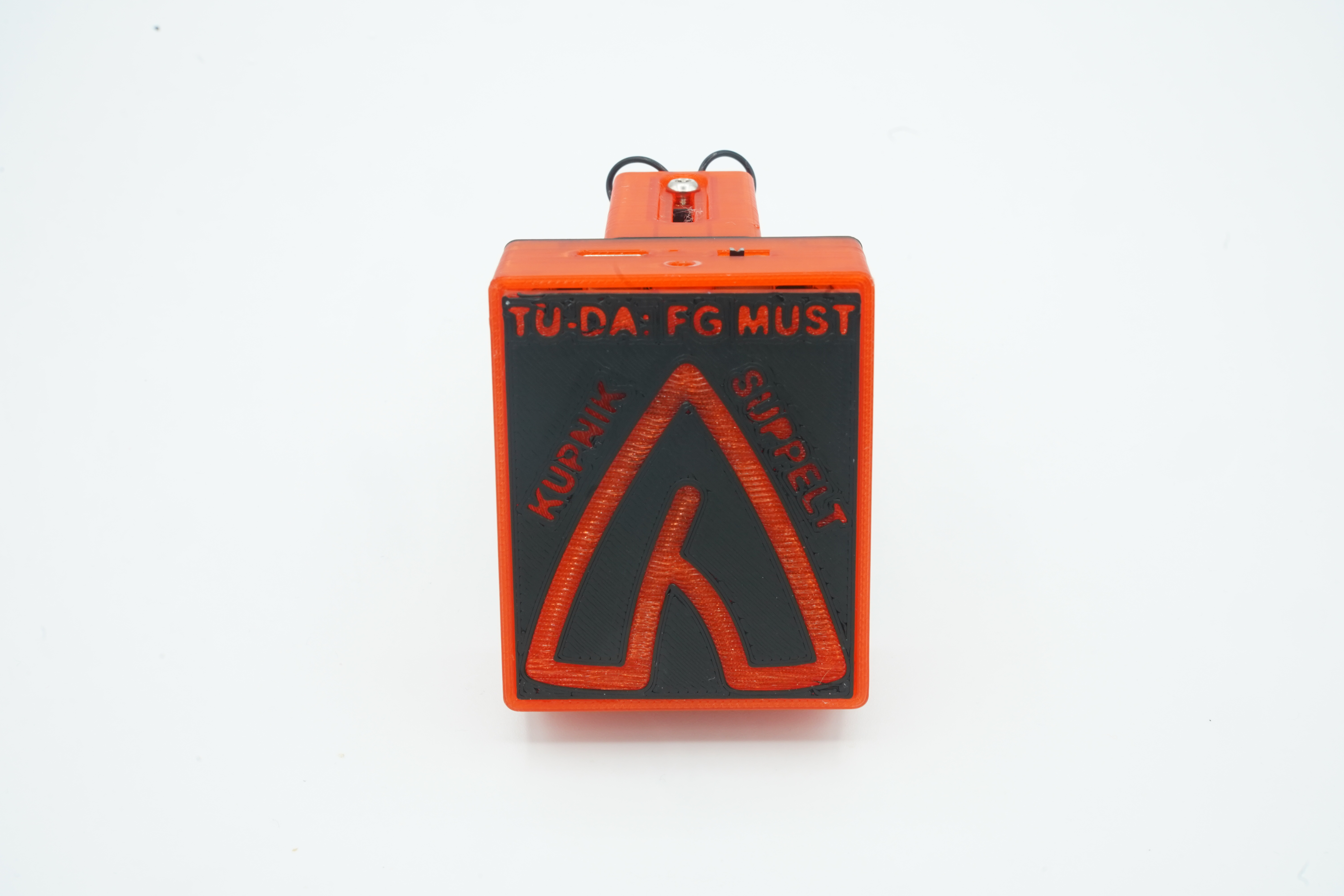
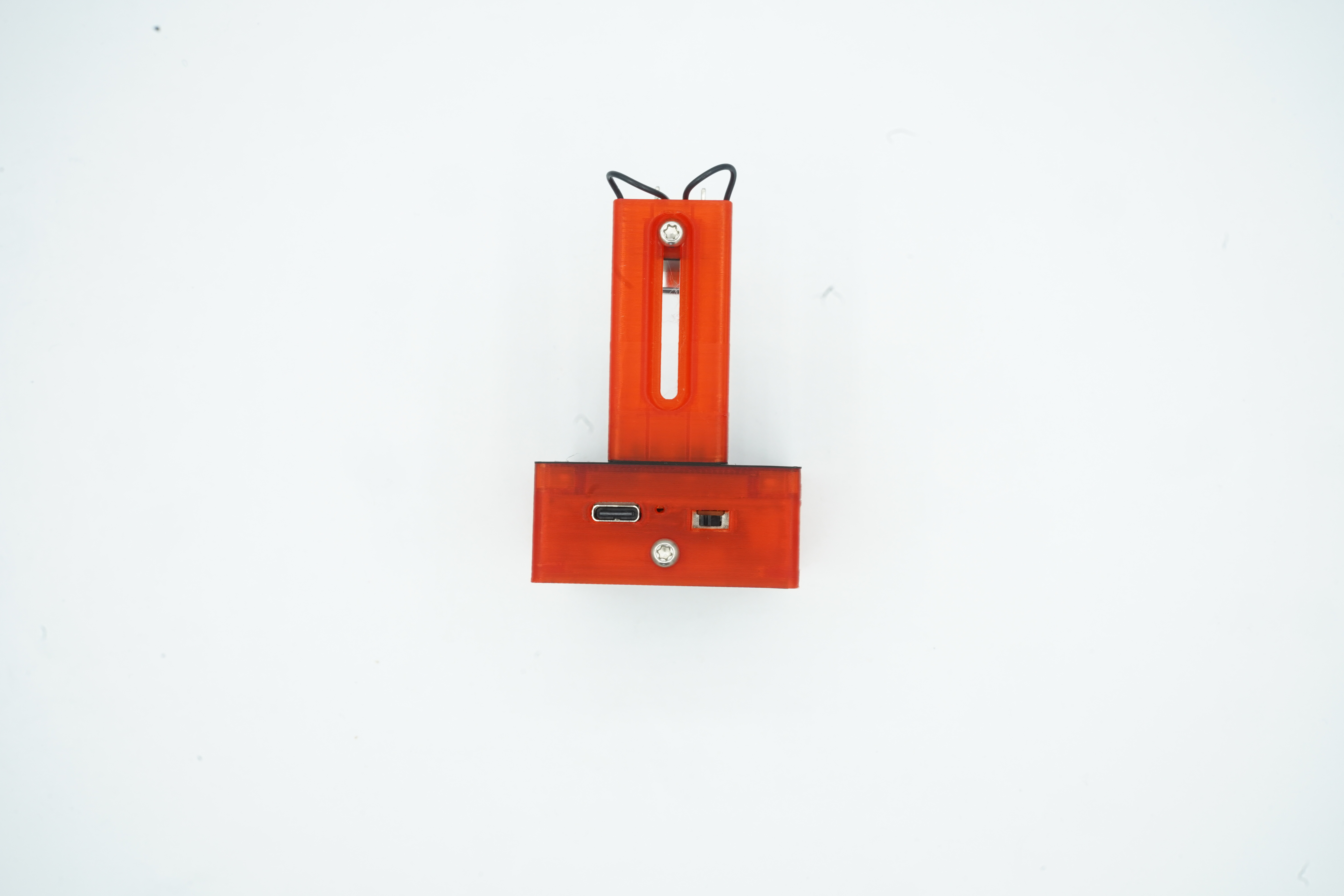
Here's a Quickstart Guide on how to use Platform IO with Visual Studio Code.
To enable working with the underlying microcontroller (ESP32-S3-MINI-1-N4R2) you are required to install the relevant board package. To do this, open Tools > Board > Boards Manager and install the 'esp32' package by Espressif Systems.
The Board should be set to Adafruit Feather ESP32-S3 2MB PSRAM as this comes closest to the used microcontroller. The relevant options under Tools should be set according to the following image. Make sure to enable USB CDC on Boot, which permits USB communication.
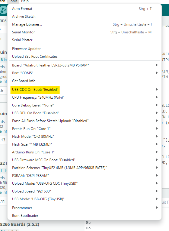
Since this board does not use a separate usb-to-serial chip, the microcontroller needs to be put into the bootloading state manually. To accomplish this, simply hold down down the BOOT button on the PCB and then quickly press the Reset button once. After releasing the BOOT button, you are now able to upload your code.
! The COM Port is likely to change after entering Boot-mode and may need to be set again in your Software !
| Pin | Name | Description |
|---|---|---|
| 1 | LED_YELLOWGREEN | emits yellow-green light (current sink!) |
| 2 | LED_RED | emits red light (current sink!) |
| 4 | HBRIDGE_ENABLE | HIGH enables the h_bridge/output for both transducers |
| 5 | HBRIDGE_A_NORMAL | PWM Input for Transducers A |
| 6 | HBRIDGE_A_INVERTED | inverted PWM Input for Transducers A |
| 7 | HBRIDGE_B_NORMAL | PWM Input for Transducers B |
| 8 | HBRIDGE_B_INVERTED | inverted PWM Input for Transducers B |
| 9 | HBRIDGE_CURRENTSENSE | read analog voltage to measure transducer current consumption |
| 10 | BAT_STATE | used to read battery voltage |
| 40 | MISO | SCPI |
| 41 | SCK | SCPI |
| 41 | MOSI | SCPI |
The LEDs are setup in a current sink configuration, meaning a LOW signal will emit light while a HIGH signal will shut them off. Consider the command GPIO.func_out_sel_cfg[PIN].inv_sel = 1 to reverse this.
The HBRIDGE_* inputs require either the typical PWM signal or the inverted one. The easiest way to achieve this is to set both to the same LEDC Channel and invert one output with the already mentioned command.
CURRENTSENSE can be used to measure the current consumption of the h-bridge, so both transducers simultaneously.
Current is measured via a 500mΩ high side shunt.
The voltage across which is amplified by a factor of 100 and then averaged with a low pass filter.
As a result, the average current consumption can be calculated by measuring the voltage on Pin "HBRIDGE_CURRENTSENSE" and dividing it by 50.
BAT_STATE can be used to read the battery voltage. However, it is reduced by a voltage divider. Multiply the measured voltage by 11 to read the correct voltage level.
! As a small sidenote, the used microcontroller ESP32 does not have a very accurate, integrated ADC. However, finding the peak voltage is sufficient to determine the resonant frequency. !
This project is licensed under the GNU GENERAL PUBLIC LICENSE Version 3, 29 June 2007. Please see the LICENSE file for more details.
If you would like to reference our project, feel free to support us by citing our research paper:
AcoustiFly: An Open-Source, Low-Cost Acoustic Levitator for Hands-On STEM Education
@inproceedings{Suppelt2025,
  title = {AcoustiFly: An Open-Source,  Low-Cost Acoustic Levitator for Hands-On STEM Education},
  url = {http://dx.doi.org/10.1109/educon62633.2025.11016546},
  DOI = {10.1109/educon62633.2025.11016546},
  booktitle = {2025 IEEE Global Engineering Education Conference (EDUCON)},
  publisher = {IEEE},
  author = {Suppelt,  Mark and Suppelt,  Sven and D\"{o}rsam,  Jan Helge and Altmann,  Alexander A. and Kupnik,  Mario},
  year = {2025},
  month = apr,
  pages = {1–5}
}
(or click here if you want to read the paper without having to go through a paywall)
| Qty | Value | Footprint | References |
|---|---|---|---|
| 2 | MCS08 | ULHolder:MCS08 | LSP1, LSP2 |
| 2 | TPTP20SQ | ULHolder:TP20SQ | TP1, TP2 |
| 1 | LOGO | LOGO | G*** |
| 1 | MountingHole | MountingHole:MountingHole_3.2mm_M3 | H1 |
byrantech/laptop
anyon_e, a highly integrated, high end, open source laptop. Attempt the impossible.


Jcparkyn/dpoint
Open-source digital stylus using camera tracking and inertial measurements

VoronDesign/Voron-Hardware
Cool Hardware designed by the Voron Design group

hoglet67/RGBtoHDMI
Bare-metal Raspberry Pi project that provides pixel-perfect sampling of Retro Computer RGB/YUV video and conversion to HDMI

hackclub/OnBoard
💡 Join 1,000 teenagers and make your first PCB with a $100 grant!

Luos-io/luos_engine
Open-source and real-time orchestrator for cyber-physical-systems, to easily design, test and deploy embedded applications and digital twins.

It measures 31 × 10 mm and has 2 copper layers, 1.6 mm thick.
6 parts. The full list of its parts is on this page, with links to each part's symbol and footprint where PCBKit's library has them.
From the TUDA-MUST/AcoustiFly repository on GitHub, at the commit this page was made from: the board is PCB/Transducer Plate/ULHolder.kicad_pcb and its schematic PCB/Transducer Plate/ULHolder.kicad_sch. PCBKit opens the board in the browser, with nothing to install.
Its repository publishes it under the GPL-3.0 licence: you may reuse it on that licence's terms (keep the author's notice, and for a copyleft licence share your changes alike).