2 layers87 × 72 mm

 TG9541/rs485-ch340e15
A small CH340E based configurable RS485 or TTL 2/3-wire USB dongle
Rs485-ch340e is an open-source printed circuit board by TG9541, from the TG9541/rs485-ch340e repository on GitHub, published under the MIT licence. It is a 2-layer board of 16.9 × 14.4 mm with 17 parts on 15 nets, routed with 154 tracks and 19 vias.
It is built around the CH340E, SP3485CN-L and XC6206P332MR. Its parts include 3 capacitors, 3 ICs, 3 diodes, 2 resistors and 2 connectors. It belongs with the interfaces and adapters boards of this library.



I needed a USB-RS485 dongle with reliable automatic direction control but it was impossible to find anything that's both reliable and cheap (not to speak of small). The "budget" cmmercial USB-RS485 dongles "try" to implement direction controll with the host's Tx signal. The timing of such a solution is tricky (and potentially unreliable). A "popular" work-around is using a questionable "dominant-recessive" approach to RX-TX switching with a "CAN network style" recessive default state. Such a hack is certainly not RS485 compliant and may randomly fail if multiple nodes are connected, the bus cable is long, at higher bit-rates, if the weather changes, or in any combination of that.
Fortunately, the very cheap CH340E provides a true RX/TX direction signal that can be used for controlling an RS485 transceiver with perfect timing. I was surprised that there are still no cheap CH340E based RS485 dongles on the market - so I decided to make one. This repository provides a small CH340E based configurable RS485 or TTL 2/3-wire USB dongle.
If you're "shopping" for ideas how to use this solution down for a mass-market product: it's certainly possible to make solution with a minimal BOM, or one with additional robustness. Feel free to writen me an issue if you want to learn how.
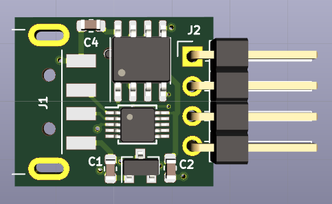
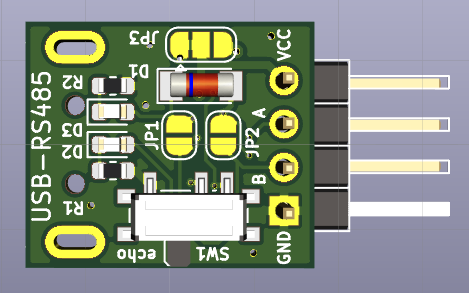
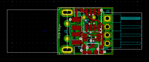
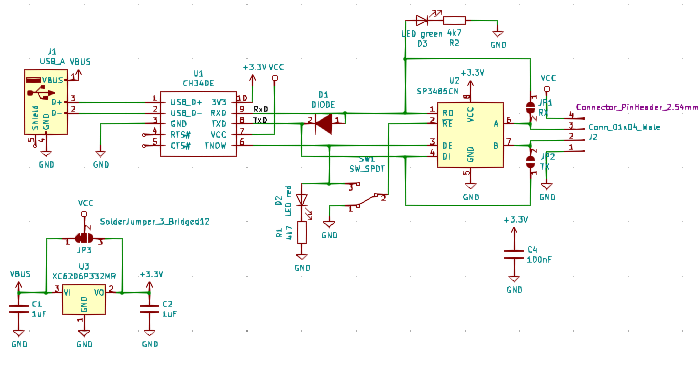
The BOM is in the doc folder.
Note: the supply voltage of U1 can be selected with J3. It is either 5V (default) or 3.3V (1-2 open, 2-3 closed). This configuration option has not been tested.
The built-in CH340E 3.3V LDO can provide a 3.3V supply for the RS485 transceiver which makes populating the linear voltage regulator U3 (XC6206P332MR) optional. For most applications it's better to populate U3 since the maximum number of RS485 nodes that can be connected to the bus might be limited by the current that the internal LDO can provide.
Note: SW1 controlls "TX-RX echo" (pin1-1 closed) or "no echo" (pin2-3 closed, this is standard RS485 functionality). If switching isn't required the pads can be bridged with a bit of solder. Most people won't need switching and in a re-design I would certainly replace SW1 with a jumper.
Populate the following:
Populate the following:
The dongle can be configured for 3-wire (full duplex) or 2-wire (half duplex) communication. The 2-wire option can be used for command-response console protocols, e.g., the half-duplex STM8 eForth configuration.
Populate the following:
Close jumpers J1 (RX, J2.3) and J2 (TX, J2.2) on the back side.
Populate the following:
Close jumpers J1 (RX/TX, J2.3) on the back side.
| Qty | Value | Footprint | References |
|---|---|---|---|
| 2 | 1uF | Capacitor_SMD:C_0603_1608Metric | C1, C2 |
| 2 | 4k7 | Resistor_SMD:R_0603_1608Metric | R1, R2 |
| 1 | 100nF | Capacitor_SMD:C_0603_1608Metric | C4 |
| 1 | CH340E | Package_SO:TSSOP-10_3x3mm_P0.5mm | U1 |
| 1 | Conn_01x04_Male | Connector_PinHeader_2.54mm:PinHeader_1x04_P2.54mm_Horizontal | J2 |
| 1 | DIODE | Diode_SMD:D_MiniMELF | D1 |
| 1 | LED green | LED_SMD:LED_0603_1608Metric | D3 |
| 1 | LED red | LED_SMD:LED_0603_1608Metric | D2 |
| 1 | RX | Jumper:SolderJumper-2_P1.3mm_Open_RoundedPad1.0x1.5mm | JP1 |
| 1 | SP3485CN | Package_SO:SOIC-8_3.9x4.9mm_P1.27mm | U2 |
| 1 | SW_SPDT | Button_Switch_SMD:SW_SPDT_PCM12 | SW1 |
| 1 | SolderJumper_3_Bridged12 | Jumper:SolderJumper-3_P1.3mm_Bridged12_RoundedPad1.0x1.5mm | JP3 |
| 1 | TX | Jumper:SolderJumper-2_P1.3mm_Open_RoundedPad1.0x1.5mm | JP2 |
| 1 | USB_A | Connector_USB:USB_A_CNCTech_1001-011-01101_Horizontal | J1 |
| 1 | XC6206P332MR | Package_TO_SOT_SMD:SOT-23 | U3 |

TG9541/stm8s001rs485
A narrow KiCad made PCB with STM8S001J3, RS485 driver and DS1621S Thermometer, e.g., for STM8EF-MODBUS


Grippy98/Beagle-Serial-Adapter
A CH340E Based Minimalist USB-Serial Adapter for BeaglePlay, AI64 and More


ROAR-QUTRC/perseus-v3
The code base for the QUT Robotics Club ROAR teams rover Perseus starting 2026

NarodniySputnik/Gladiolus-1
Gladiolus-1 - автономный модуль для приема и передачи изображений в формате SSTV (Slow Scan TeleVision) на малом космическом аппарате (МКА) формата CubeSat
It measures 16.9 × 14.4 mm and has 2 copper layers, 1 mm thick.
17 parts, built around the CH340E, SP3485CN-L and XC6206P332MR. The full list of its parts is on this page, with links to each part's symbol and footprint where PCBKit's library has them.
From the TG9541/rs485-ch340e repository on GitHub, at the commit this page was made from: the board is RS485-CH340E.kicad_pcb. PCBKit opens the board in the browser, with nothing to install.
Its repository publishes it under the MIT licence: you may reuse it on that licence's terms (keep the author's notice, and for a copyleft licence share your changes alike).