Skip to the content
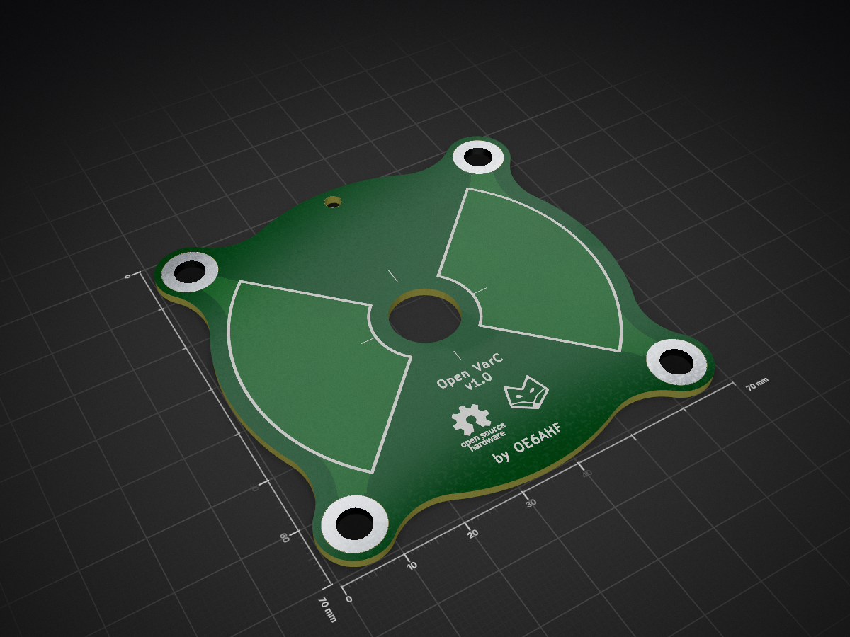
2 layers82.1 × 82.1 mmOpenVarC large Stator, the printed circuit board in 3D

OpenVarC large Stator

SwiftyTheFox001/OpenVarC2

OSHW Variable Capacitor based on PCBs

Size
82.1 × 82.1 mm
Copper layers
2
Thickness
1.6 mm
Parts
7
Nets
2
Pads
13
Tracks, vias
0, 0
Pours
2
Routed
Not yet
KiCad
KiCad 5 (file 20171130)
Created
21 Feb 2022
Updated
28 Feb 2022

Overview

OpenVarC large Stator is an open-source printed circuit board by SwiftyTheFox001, from the SwiftyTheFox001/OpenVarC repository on GitHub, published under the CC-BY-SA-4.0 licence. It is a 2-layer board of 82.1 × 82.1 mm with 7 parts on 2 nets.

README

README.md

OpenVarC

OSHW Variable Capacitor based on PCBs

This project intends to find a viable alternative for the variable capacitors for high voltages that got rare in modern electronics, but are still in demand for ham radio operators for various projects. At the moment this project is still in "beta phase" covers only one size of cap and some specs are still to be tested like the max. AC voltage capability. Please consider this while rebuilding a capacitor.

Features:

  • Modular
  • Uses PCBs and easily available mechanic parts (metric screws, washers & nuts)
  • at least 2kV
  • Holes for light barrier to allow automatic centering

Future development:

  • different sizes
  • measuring max. Voltage capability
  • optimizing the center tapped

On ordering the PCBs:

  • Thickness: 0.8mm
  • Amount of PCBs: use calculations.ods to calculate the approximate amount of needed stacks and order a bit more. The amount depends on the dielectric properties of the used FR4 material. Milage may vary!

What you need for the large VarCs:

  • Stator plate PCBs
  • Rotor plate PCBs
  • 4x M4 threaded rods of the same length
  • 16x M4 Nuts
  • M4 Washers (4 between 2 stators)
  • 8mm rectangular aluminium extrusion (Axis) Note: Can be a U-shaped extrusion as well
  • Cable shoes that fit on the M4 threaded rod
  • 3D printed parts:
    • 2x H750.stl
    • 1x H751_1.stl
    • 1x H751_2.stl
  • a Saw

Assembly:

  1. Lengthen the rectrangular axis and the 4 threaded rods depending on your need. Calculate some extra length to ensure that you can add a few stacks later if needed
  2. put one M4 Nut min. 1cm from the ends of each threaded rod
  3. Stack the PCBs the following way:
  • Slide stator plate with silk screen showing upside (text/markings) on the four threaded rods
  • First stack: put the axis inside the circular center hole of the stator plate
  • Slide rotor plate with silk screen showing upside (text/markings) on the Axis
  • Slide one washer on each of the threaded rods
  • repeat the process with sliding a stator plate on top and ensure that the light barrier hole is aligned with the bottom layers
  1. finishing the assembly
  • ensure that all outside plates are stator plates
  • put 4 M4 Nuts on top of thestack and tighten them carefully
  • put the 3D printed parts 751_1 and 751_2 on both ends of the axis. Move the axis so, that the part 751_2 (endcap that prevents axis from going throuh) lies flush with the stator plate
  • slide the two 3D printed parts 750 on the ends of the caps. Ensure that the light barrier holes are aligned
  • slide the cable shoes on the threaded rods
  • tighten with with M4 nuts

Parts

7
QtyValueFootprintReferences
4MountingHole_PadMountingHole:MountingHole_5.3mm_M5_ISO7380_Pad_TopBottomH1, H2, H3, H4
1LOGOrelayclock:foxG***

The 5 most common of 7 parts.

Similar boards

  • 2 layersEncoder, the printed circuit board in 3D

    Encoder

    byrantech/laptop

    anyon_e, a highly integrated, high end, open source laptop. Attempt the impossible.

    7 parts4.3kMIT
  • 2 layers40 × 20 mmSensor smd, the printed circuit board in 3D

    Sensor smd

    scottbez1/splitflap

    DIY split-flap display

    7 parts4.2k
  • 2 layers19.8 × 30 mmZ limit, the printed circuit board in 3D

    Z limit

    opulo-inc/lumenpnp

    The LumenPnP is an open source pick and place machine.

    7 parts3.7k
  • 2 layers35.6 × 58.2 mmDisplay Carrier, the printed circuit board in 3D

    Display Carrier

    AxxAxx/AxxSolder

    STM32 Based soldering station for JBC cartridges, 9-24 VDC and USB-PD power

    7 parts1.7kGPL-3.0
  • 2 layers20.3 × 16.3 mmMap MPX, the printed circuit board in 3D

    Map MPX

    rusefi/rusefi

    rusefi - GPL internal combustion engine control unit

    7 parts1.2k
  • 2 layers26 × 44 mmCompact carrier board, the printed circuit board in 3D

    Compact carrier board

    jamro/tiny-engineer

    A small desktop robot that brings an AI coding assistant to life, physically acting out when it reads files, thinks, writes code, and finishes work.

    7 parts1.1k
  • 2 layers26.4 × 53.8 mmAtari pickup, the printed circuit board in 3D

    Atari pickup

    hoglet67/RGBtoHDMI

    Bare-metal Raspberry Pi project that provides pixel-perfect sampling of Retro Computer RGB/YUV video and conversion to HDMI

    7 parts1kGPL-3.0
  • 2 layersRj45 breakout, the printed circuit board in 3D

    Rj45 breakout

    rene-dev/stmbl

    AC Servo Driver for STM32F4

    7 parts990GPL-3.0

Questions

How big is the OpenVarC large Stator PCB?

It measures 82.1 × 82.1 mm and has 2 copper layers, 1.6 mm thick.

What parts does the OpenVarC large Stator use?

7 parts. The full list of its parts is on this page, with links to each part's symbol and footprint where PCBKit's library has them.

Where can I download the OpenVarC large Stator KiCad files?

From the SwiftyTheFox001/OpenVarC repository on GitHub, at the commit this page was made from: the board is VarCo_large/openVarC_large_Stator/openVarC_large_Stator.kicad_pcb. PCBKit opens the board in the browser, with nothing to install.

Can I use the OpenVarC large Stator design in my own project?

Its repository publishes it under the CC-BY-SA-4.0 licence: you may reuse it on that licence's terms (keep the author's notice, and for a copyleft licence share your changes alike).