
2 layers76 × 90 mm

IBM M122 USB / BLE keyboard controller
M122 is an open-source printed circuit board by SvenHaedrich, from the SvenHaedrich/m122_keyboard repository on GitHub. It is a 4-layer board of 140 × 50 mm with 62 parts on 89 nets, routed with 649 tracks and 92 vias.
It is built around the AP2112K-3.3, DMG2305UX and MBR0540, with the PRTR5V0U2X among its other parts. Its parts include 20 capacitors, 16 resistors, 6 connectors, 4 inductors and 3 ICs. It belongs with the keyboards and input and radio and wireless boards and the nRF52 and nRF5x boards of this library.


Project for an IBM M122 keyboard controller
This is a project that replaces the original part from IBM with a nice modern solution. It features a nRF52840 microcontroller and allows to use the keyboard via USB connector, or via Bluetooth.
The firmware is based on the ZMK project.
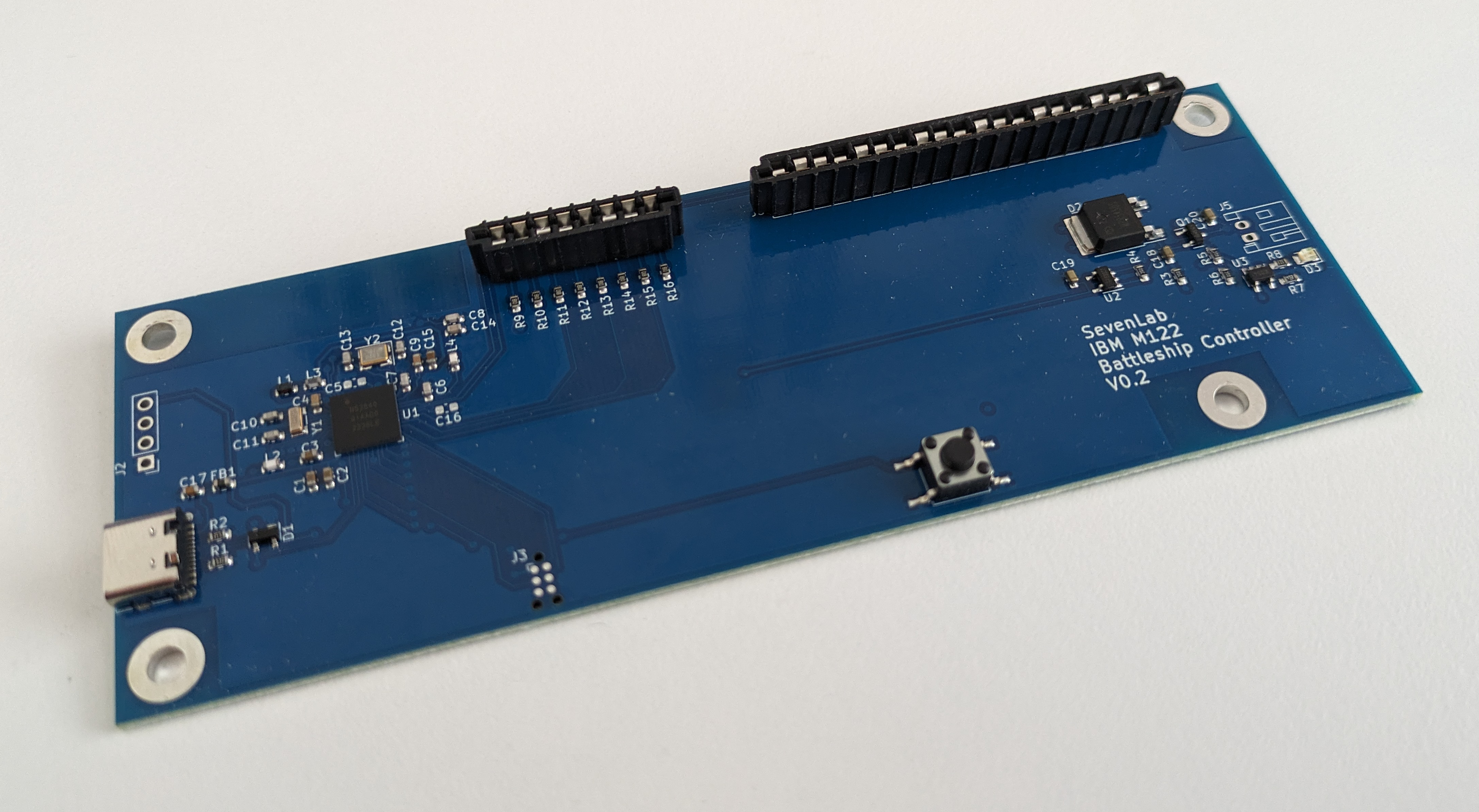
Beside the assembled PCB you require:
You need a debug adapter (JLink) with 6 pin Tag-Connect for the initial flash programming of the board
When ordering the pcb from JLC you need to specify
push and pull_request trigger a github-action to build the firmware. To locate the build output
go to the Actions tab and open the respective workflow run. There you find a link to the artifacts
generated by the run. You can download it and unpack the .zip archive to access the .UF2 file.
This repository follows the versions of the ZMK project. For details, please refer to the Release Log.
To update the firmware activate the bootloader.
By default you can start the bootloader by hitting the bootloader key.
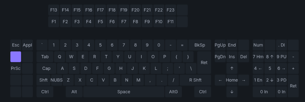 If successful, this will mount your keyboard as a USB mass storage device to your computer.
Now, you can install the firmware by simply drag and drop the UF2 file to the mounted device.
To connect the keyboard to ZMK Studio open this link.
Google's chrome is the preferred browser for this app.
Select the connection to your keyboard.
You need to press the studio unlock key on your keyboard to establish the connection.
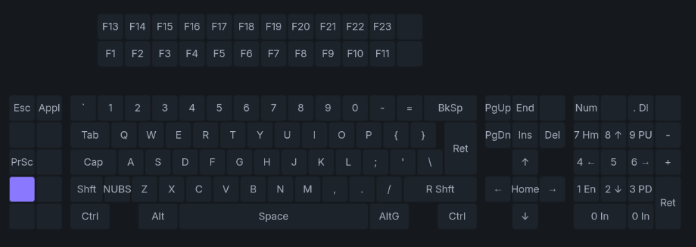
The project uses a modified Adafruit bootloader.
You might want to test the basic electric functionality of the PCB. To do so, flash the firmware and connect the PCB to a computer´s USB port. To view detailled event codes start
sudo evtestSelect your M122 controller as event source. Now, you can short individual rows and columns. Expected results are given for German keyboard layout.
| Row | Column | Keycode |
|---|---|---|
| 1 | 16 | KEY_KP0 |
| 1 | 8 | KEY_B |
| 2 | 8 | KEY_V |
| 3 | 13 | KEY_RIGHTBRACE |
| 4 | 5 | KEY_Q |
| 5 | 9 | KEY_6 |
| 6 | 12 | KEY_F5 |
| 7 | 1 | KEY_PPLUS |
| 8 | 15 | KEY_APOSTROPHE |
| 2 | 2 | KEY_KP1 |
| 2 | 3 | KEY_CAPSLOCK |
| 1 | 4 | KEY_LEFTSHIFT |
| 1 | 20 | KEY_ENTER |
| 1 | 19 | KEY_KPCOMMA |
| 2 | 18 | KEY_KP2 |
| 2 | 17 | KEY_INSERT |
| 4 | 15 | KEY_P |
| 6 | 14 | KEY_9 |
| 4 | 11 | KEY_F7 |
| 3 | 10 | KEY_F20 |
| 7 | 6 | KEY_S |
| 7 | 7 | KEY_D |
| Qty | Value | Footprint | References |
|---|---|---|---|
| 8 | 1k | Resistor_SMD:R_0603_1608Metric | R9, R10, R11, R12, R13, R14, R15, R16 |
| 4 | 100k | Resistor_SMD:R_0603_1608Metric | R3, R4, R5, R6 |
| 4 | 12pF | Capacitor_SMD:C_0603_1608Metric | C10, C11, C12, C13 |
| 4 | MountingHole | MountingHole:MountingHole_3.7mm_Pad | H1, H2, H3, H4 |
| 3 | 10uF | Capacitor_SMD:C_0603_1608Metric | C18, C19, C20 |
| 3 | 4u7F | Capacitor_SMD:C_0603_1608Metric | C1, C2, C3 |
| 2 | 4n7H | Inductor_SMD:L_0603_1608Metric | L2, L4 |
| 2 | 5k1 | Resistor_SMD:R_0603_1608Metric | R1, R2 |
| 2 | DNP | Capacitor_SMD:C_0603_1608Metric | C5, C16 |
| 1 | 0.5pF | Capacitor_SMD:C_0603_1608Metric | C8 |
| 1 | 0.8pF | Capacitor_SMD:C_0603_1608Metric | C6 |
| 1 | 1.2pF | Capacitor_SMD:C_0603_1608Metric | C14 |
| 1 | 100nF | Capacitor_SMD:C_0603_1608Metric | C4 |
| 1 | 100pF | Capacitor_SMD:C_0603_1608Metric | C7 |
| 1 | 10n | Capacitor_SMD:C_0603_1608Metric | C17 |
| 1 | 10uH | Inductor_SMD:L_0603_1608Metric | L1 |
| 1 | 120R | Resistor_SMD:R_0603_1608Metric | R8 |
| 1 | 15nH | Inductor_SMD:L_0603_1608Metric | L3 |
| 1 | 1uF | Capacitor_SMD:C_0603_1608Metric | C15 |
| 1 | 300R @ 100 MHz | Resistor_SMD:R_0603_1608Metric | FB1 |
| 1 | 32MHz | Crystal:Crystal_SMD_TXC_7M-4Pin_3.2x2.5mm | Y2 |
| 1 | 32k768Hz | Crystal:Crystal_SMD_3215-2Pin_3.2x1.5mm | Y1 |
| 1 | 47nF | Capacitor_SMD:C_0603_1608Metric | C9 |
| 1 | 4k7 | Resistor_SMD:R_0603_1608Metric | R7 |
| 1 | AP2112K-3.3 | Package_TO_SOT_SMD:SOT-23-5 | U2 |
| 1 | Antenna | RF_Antenna:Texas_SWRA117D_2.4GHz_Right | AE1 |
| 1 | Conn_01x02_Pin | Connector_JST:JST_PH_S2B-PH-K_1x02_P2.00mm_Horizontal | J5 |
| 1 | Conn_01x08_Socket | Connector_PinHeader_2.54mm:PinHeader_1x08_P2.54mm_Vertical | J4 |
| 1 | Conn_01x20_Socket | Connector_PinHeader_2.54mm:PinHeader_1x20_P2.54mm_Vertical | J6 |
| 1 | Conn_02x03_Odd_Even | Connector:Tag-Connect_TC2030-IDC-NL_2x03_P1.27mm_Vertical | J3 |
| 1 | DMG2305 | Package_TO_SOT_SMD:SOT-23 | Q1 |
| 1 | LED green | LED_SMD:LED_0805_2012Metric | D3 |
| 1 | MBR054 | Package_TO_SOT_SMD:TO-252-2 | D2 |
| 1 | MCP73831-2-OT | Package_TO_SOT_SMD:SOT-23-5 | U3 |
| 1 | PRTR5V0U2X | Package_TO_SOT_SMD:SOT-143 | D1 |
| 1 | SW_Push | m122-models:SW_TS665TP | SW1 |
| 1 | USB_C | Connector_USB:USB_C_Receptacle_XKB_U262-16XN-4BVC11 | J1 |
| 1 | USB_Ext | Connector_PinHeader_2.54mm:PinHeader_1x04_P2.54mm_Vertical | J2 |
| 1 | nRF52840 | Package_DFN_QFN:Nordic_AQFN-73-1EP_7x7mm_P0.5mm | U1 |

3pnguyen/esp32-bluetooth-media-keyboard
Electronic project that provides the same control as wireless earbuds.

oomlout/oomlout_oomp_project_bot_v_2

rishikesh2715/RP2040_Motion_Logger
An RP2040 based microcontroller with an ICM-42688 IMU, 1S Battery Charger, SD Card Connector, RGB Led, and USB Type-C connector


rohamid/chroma-pixel-zeta
The minimal configuration of Chroma Pixel board for GUI application


mikelawrence/WiFi-Septic-Controller
WiFi enabled Septic Controller
It measures 140 × 50 mm and has 4 copper layers, 1.6 mm thick.
62 parts, built around the AP2112K-3.3, DMG2305UX, MBR0540 and PRTR5V0U2X. The full list of its parts is on this page, with links to each part's symbol and footprint where PCBKit's library has them.
From the SvenHaedrich/m122_keyboard repository on GitHub, at the commit this page was made from: the board is m122/m122.kicad_pcb and its schematic m122/m122.kicad_sch. PCBKit opens the board in the browser, with nothing to install.
Its repository states no licence, so its author keeps all rights: ask SvenHaedrich before reusing the design.