Skip to the content
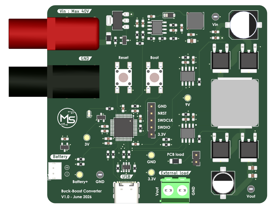
4 layers80 × 72 mmConvertisseur DC DC, the printed circuit board in 3D

4-switch buck-boost DC/DC converter

Size
80 × 72 mm
Copper layers
4
Thickness
1.61 mm
Parts
88
Nets
77
Pads
303
Tracks, vias
414, 103
Pours
6
Routed
Yes
KiCad
KiCad 9.0 (file 20241229)
Created
5 Jul 2026
Updated
7 Jul 2026

Overview

Convertisseur DC DC is an open-source printed circuit board by SurquinMathieu, from the SurquinMathieu/buck-boost-converter repository on GitHub. It is a 4-layer board of 80 × 72 mm with 88 parts on 77 nets, routed with 414 tracks and 103 vias.

It is built around the UCC27282DRC, TPS54360BDDAR and MCP1700T-3302E/TT(MS), with the IPD053N06NATMA1, 0685T6000-01 and 150060SS75000 among its other parts. Its parts include 26 capacitors, 26 resistors, 7 connectors, 6 ICs and 5 transistors. It belongs with the power boards and the STM32 boards of this library.

Main components

12

README

README.md

Buck-Boost DC/DC Converter

A 4-switch synchronous buck-boost converter built around an STM32G431CBT6, with a digital PI control loop, USB CDC telemetry, and a real-time web dashboard for monitoring and control.

Overview

This project implements a 4-switch buck-boost DC/DC converter. The STM32 runs a 300 kHz PWM control loop with real-time voltage sensing, feedforward + PI regulation, soft-start, and software UVLO protection. A companion web dashboard connects over USB to display live VIN/VOUT readings and lets you adjust the output setpoint from a browser.

Key specifications

ParameterValue
Input voltage10 – 40 V
Output voltage3 – 15 V
Max output current3 A
Switching frequency300 kHz
MCUSTM32G431CBT6 (Cortex-M4, 170 MHz)
Topology4-switch buck-boost

Features

  • Digital PI control with feedforward
  • Soft-start on power-up and on setpoint changes
  • Software UVLO (on: 12 V, off: 10 V) backed by a hardware UVLO on the gate-driver supply
  • Dual-simultaneous ADC sampling of VIN and VOUT, triggered by the timer
  • USB CDC telemetry (VIN, VOUT, target, duty cycle)
  • Web dashboard (Python/WebSocket backend + HTML/JS frontend) for live plotting and setpoint control
  • State-machine firmware architecture designed to be extended to boost and full buck-boost modes

Hardware

PCB

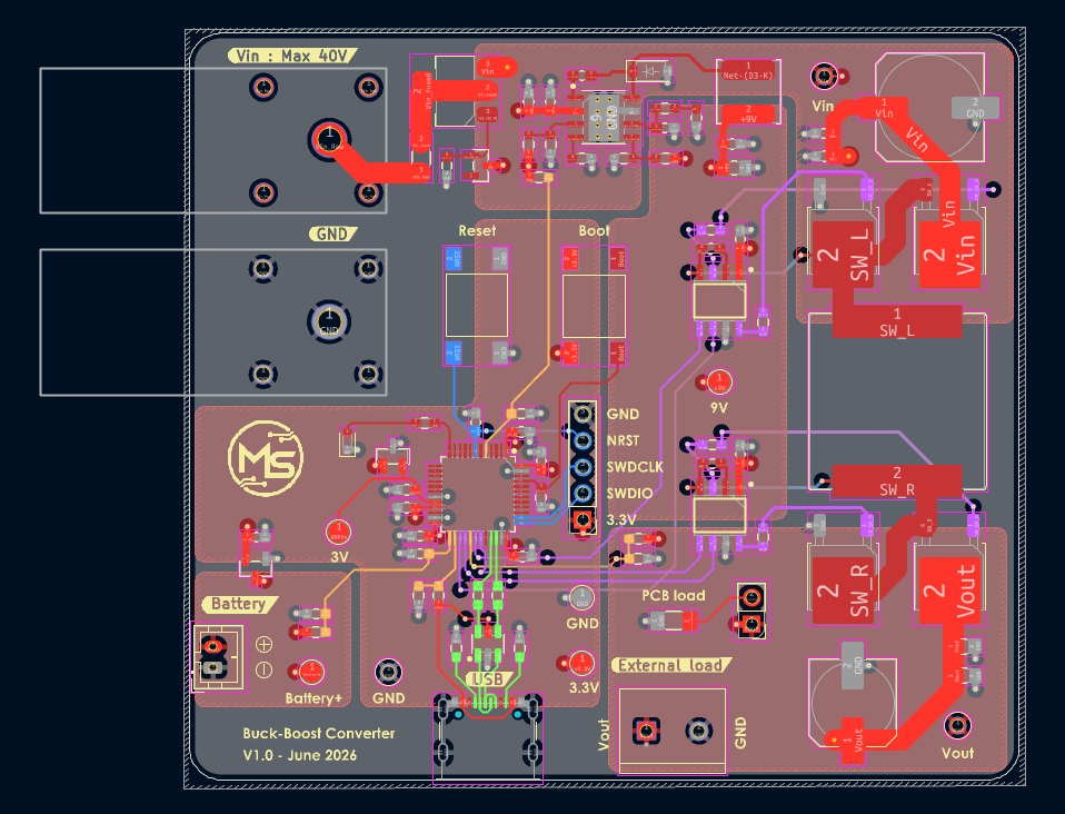
The converter uses four N-channel MOSFETs driven by two half-bridge gate drivers.

PCB layout

See hardware/kicad for the full KiCad project and hardware/bom for the bill of materials.

Firmware

See firmware/ for the STM32CubeIDE project.

Building

  1. Open the project in STM32CubeIDE (firmware/DC-DC-Converter.ioc)
  2. Build and flash to an STM32G431CBT6
  3. Connect over USB

Dashboard

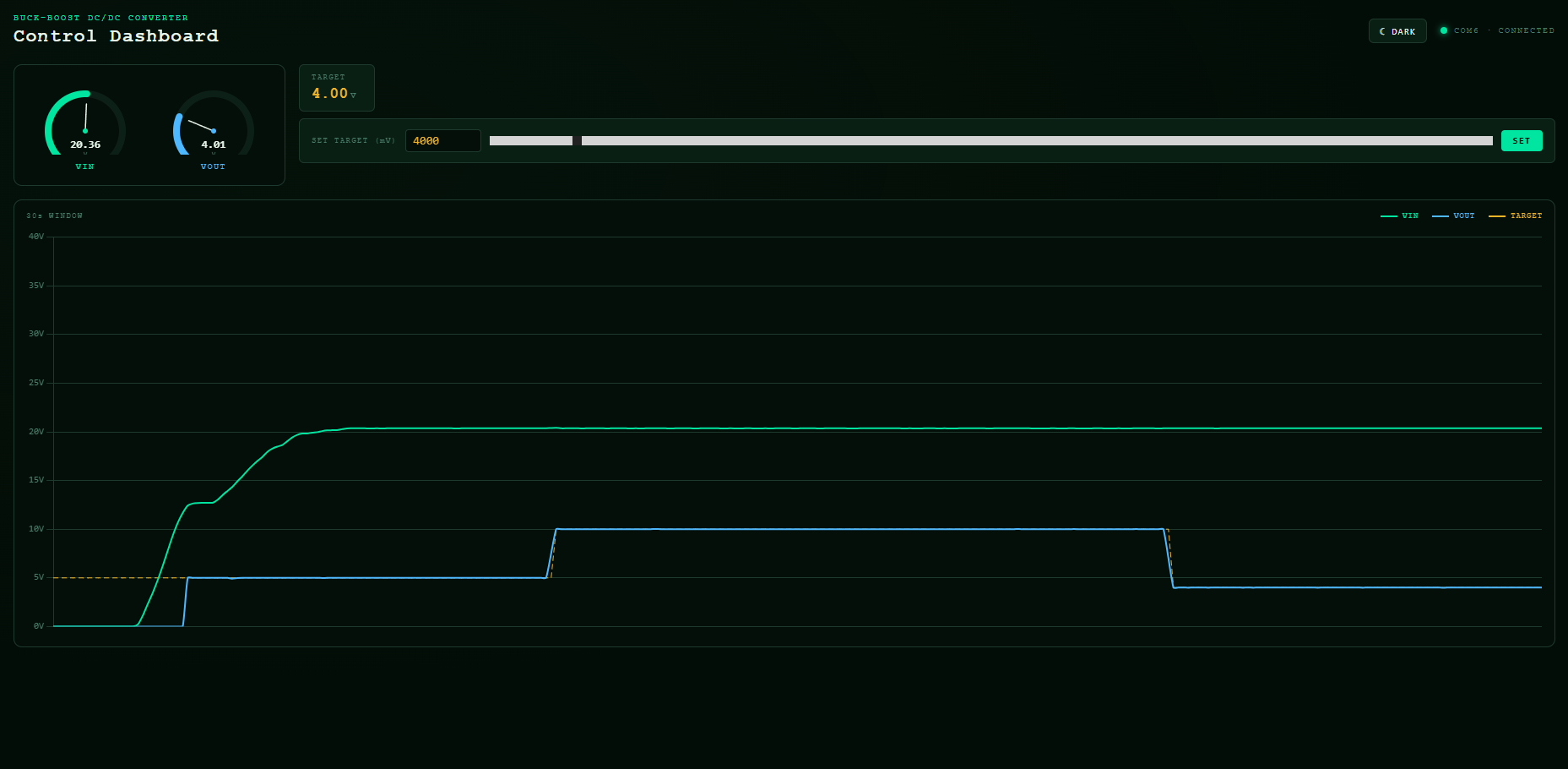
Dashboard

The dashboard connects to the board's virtual COM port and streams VIN/VOUT/target data to a browser in real time over a local WebSocket, with a live waveform plot and a setpoint control.

Running it

bash
cd dashboard
pip install pyserial websockets
python server.py

Then open index.html in a browser. Update the PORT variable in server.py to match your board's COM port.

Parts

88
QtyValueFootprintReferences
160.1uFCapacitor_SMD:C_0603_1608Metric_Pad1.08x0.95mm_HandSolderC2, C3, C4, C5, C6, C7, C8, C9, C10, C11, C12, C13, C14, C15, C16, C17
410kResistor_SMD:R_0603_1608Metric_Pad0.98x0.95mm_HandSolderR12, R13, R14, R15
44.7RResistor_SMD:R_0603_1608Metric_Pad0.98x0.95mm_HandSolderR1, R2, R3, R4
4IPD053N06NATMA1Package_TO_SOT_SMD:TO-252-2Q1, Q2, Q3, Q4
310uFCapacitor_SMD:C_0805_2012Metric_Pad1.18x1.45mm_HandSolderC22, C23, C24
2100kResistor_SMD:R_0603_1608Metric_Pad0.98x0.95mm_HandSolderR20, R21
22.2uFCapacitor_SMD:C_0603_1608Metric_Pad1.08x0.95mm_HandSolderC20, C21
222RResistor_SMD:R_0603_1608Metric_Pad0.98x0.95mm_HandSolderR5, R6
25.1kResistor_SMD:R_0603_1608Metric_Pad0.98x0.95mm_HandSolderR10, R11
2UCC27282DR1_Converter_DCDC:UCC27282DRU5, U6
10685T6000-01Fuse:Fuse_1206_3216Metric_Pad1.42x1.75mm_HandSolderF1
11.4kResistor_SMD:R_0603_1608Metric_Pad0.98x0.95mm_HandSolderR9
1100uFCapacitor_SMD:C_Elec_10x10.2C25
1102kResistor_SMD:R_0603_1608Metric_Pad0.98x0.95mm_HandSolderR22
1124kResistor_SMD:R_0603_1608Metric_Pad0.98x0.95mm_HandSolderR23
1150060SS75000LED_SMD:LED_0603_1608MetricD2
115uHInductor_SMD:L_TDK_VLS6045EX_VLS6045AFL1
1180kResistor_SMD:R_0603_1608Metric_Pad0.98x0.95mm_HandSolderR24
11kResistor_SMD:R_1206_3216Metric_Pad1.30x1.75mm_HandSolderR8
11uFCapacitor_SMD:C_0603_1608Metric_Pad1.08x0.95mm_HandSolderC19
1220uFCapacitor_SMD:C_Elec_8x10.2C26
1249kResistor_SMD:R_0603_1608Metric_Pad0.98x0.95mm_HandSolderR25
1330nFCapacitor_SMD:C_0603_1608Metric_Pad1.08x0.95mm_HandSolderC18
133kResistor_SMD:R_0603_1608Metric_Pad0.98x0.95mm_HandSolderR16
139uHInductor_SMD:L_Bourns_SRP1770TA_16.9x16.9mmL2
13VTestPoint:TestPoint_Pad_D2.0mmTP4
13V3TestPoint:TestPoint_Pad_D2.0mmTP8
140.2kResistor_SMD:R_0603_1608Metric_Pad0.98x0.95mm_HandSolderR17
1560pFCapacitor_SMD:C_0603_1608Metric_Pad1.08x0.95mm_HandSolderC1
1590kResistor_SMD:R_0603_1608Metric_Pad0.98x0.95mm_HandSolderR26
161.9kResistor_SMD:R_0603_1608Metric_Pad0.98x0.95mm_HandSolderR18
168RResistor_SMD:R_0603_1608Metric_Pad0.98x0.95mm_HandSolderR7
168kResistor_SMD:R_0603_1608Metric_Pad0.98x0.95mm_HandSolderR19
19VTestPoint:TestPoint_Pad_D2.0mmTP3
1BZX84C10Package_TO_SOT_SMD:SOT-23D1
1Boot0TS04-66-50-BK-260-SMT:SW_TS04-66-50-BK-260-SMTSW2
1Conn_01x02Connector_PinHeader_2.54mm:PinHeader_1x02_P2.54mm_VerticalJ5
1Conn_01x02Connector_JST:JST_PH_B2B-PH-K_1x02_P2.00mm_VerticalJ3
1Conn_01x05Connector_PinHeader_2.54mm:PinHeader_1x05_P2.54mm_VerticalJ7
1DMP6023LE-13Package_TO_SOT_SMD:SOT-223-3_TabPin2Q5
1FCR7350B1_Connector:FCR7350J2
1FCR7350R1_Connector:FCR7350J1
1GND1_Testpoint:5001TP6
1GNDTestPoint:TestPoint_Pad_D2.0mmTP7
1LOGOLogos:logo 11x11mG***
1MCP1700T-3302ETTPackage_TO_SOT_SMD:SOT-23U2
1RB162MM-60TRDiode_SMD:D_SOD-123D3
1REF3030EAIDBZRPackage_TO_SOT_SMD:SOT-23U3
1ResetTS04-66-50-BK-260-SMT:SW_TS04-66-50-BK-260-SMTSW1
1STM32G431CBTxPackage_QFP:LQFP-48_7x7mm_P0.5mmU1
1Screw_Terminal_01x021_Connector:TE_282837-2J6
1TPS54360BDDARPackage_SO:TI_SO-PowerPAD-8_ThermalViasU4
1USB4105-GF-AConnector_USB:USB_C_Receptacle_GCT_USB4105-xx-A_16P_TopMnt_HorizontalJ4
1USBLC6-2SC6Package_TO_SOT_SMD:SOT-23-6D4
1VbattTestPoint:TestPoint_Pad_D2.0mmTP5
1Vin1_Testpoint:5001TP2
1Vout1_Testpoint:5001TP1

Similar boards

  • 4 layers114 × 100 mmAMODO PSRR INJECTOR CBs 1, the printed circuit board in 3D

    AMODO PSRR INJECTOR CBs 1

    Amodo-Design/PSRR-Injector-Board

    Board to allow you to measure power supply rejection ratio. Allows you to inject an AC ripple on top of your DC power supply to measure downstream. 0dB from 100Hz+.

    48 parts1CERN-OHL-P-2.0
  • 4 layers97.6 × 108.3 mmProjet Velux, the printed circuit board in 3D

    Projet Velux

    louisonmalinge/Projet-Velux

    Dans ce Git, vous trouverez les fichiers ayant permis de réaliser le projet Velux, avec ses différentes versions.

    27 parts
  • 4 layersESC R1, the printed circuit board in 3D

    ESC R1

    samvangysegem/esc-pcb

    A simple ESC designed in KiCad

    230 parts
  • 4 layers175.2 × 64.7 mmMini sumo, the printed circuit board in 3D

    Mini sumo

    Dunbarin-O/Esp-Sumo

    Open source Mini sumo pcb

    96 parts

Questions

How big is the Convertisseur DC DC PCB?

It measures 80 × 72 mm and has 4 copper layers, 1.61 mm thick.

What parts does the Convertisseur DC DC use?

88 parts, built around the UCC27282DRC, TPS54360BDDAR, MCP1700T-3302E/TT(MS) and IPD053N06NATMA1. The full list of its parts is on this page, with links to each part's symbol and footprint where PCBKit's library has them.

Where can I download the Convertisseur DC DC KiCad files?

From the SurquinMathieu/buck-boost-converter repository on GitHub, at the commit this page was made from: the board is hardware/kicad/Convertisseur DC-DC.kicad_pcb. PCBKit opens the board in the browser, with nothing to install.

Can I use the Convertisseur DC DC design in my own project?

Its repository states no licence, so its author keeps all rights: ask SurquinMathieu before reusing the design.