
4 layers292.1 × 88.3 mm
Snark barker mca
schlae/snark-barker-mca
A Sound Blaster compatible sound card for Micro Channel bus computers
177 parts69
 SukkoPera/SoundX8
An AdLib card for your Commodore 16/116/+4!
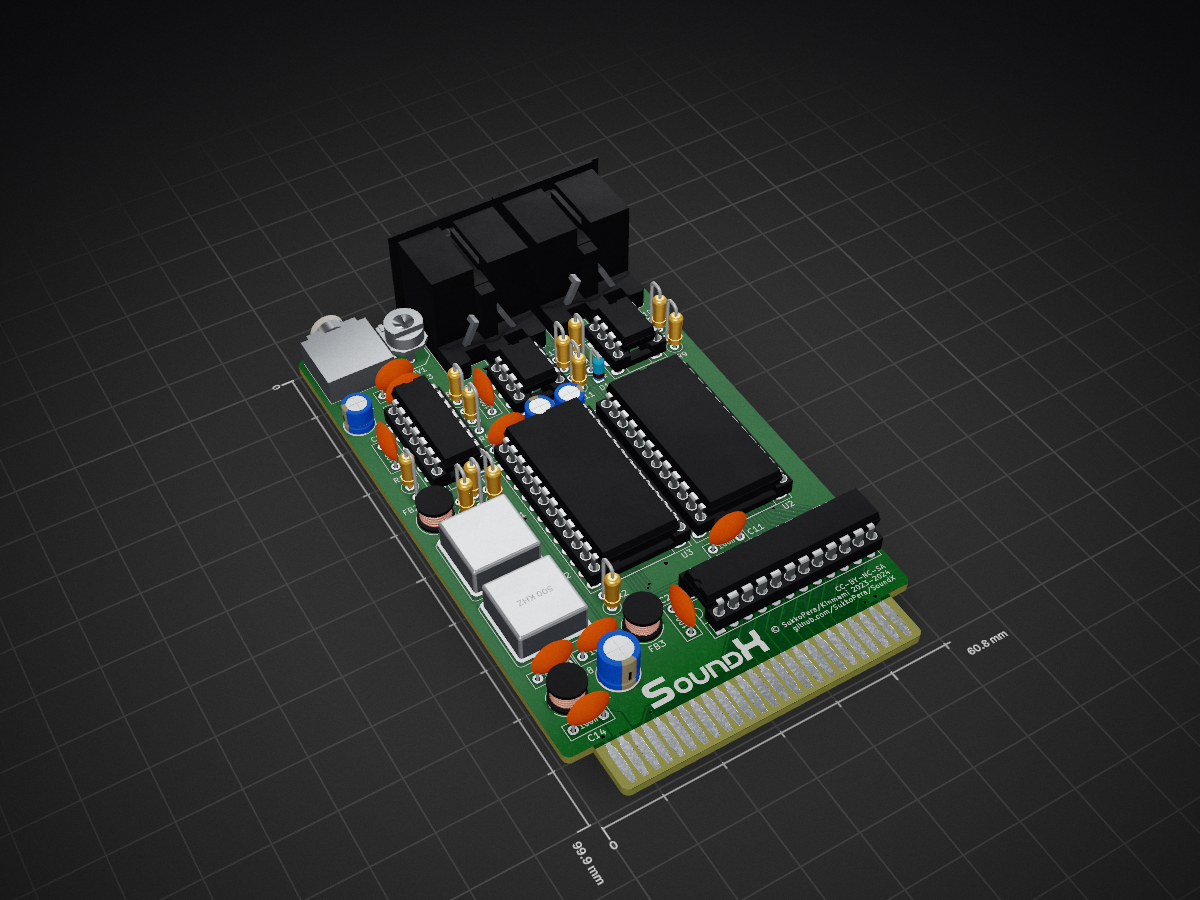
SoundX is an open-source printed circuit board by SukkoPera, from the SukkoPera/SoundX repository on GitHub. It is a 2-layer board of 60.8 × 99.9 mm with 55 parts on 102 nets, routed with 665 tracks and 58 vias.
It is built around the LM324 and 74HCT74D. Its parts include 15 capacitors, 12 resistors, 7 ICs, 4 connectors and 2 crystals. It belongs with the retro computing and games and audio and music boards of this library.



SoundX is an Open Hardware sound card for the Commodore 16, 116 and Plus/4 home computers based on the Yamaha OPL/OPL-II chip.
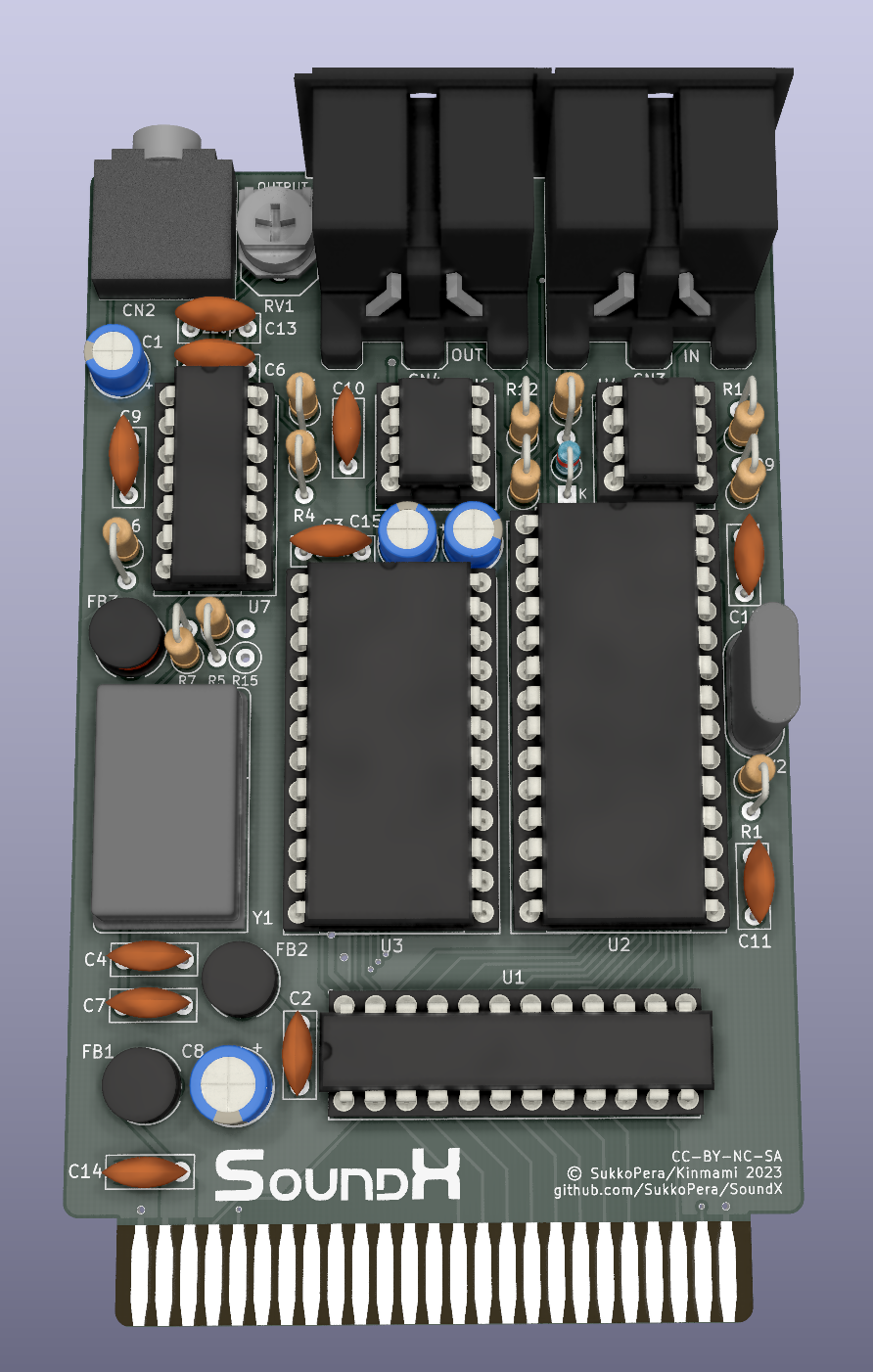
SoundX is basically an adaptation of the C64 SFX Sound Expander for the x264 series of Commodore computers.
While it didn't enjoy much success when it was released on the C64, since it was not that much superior to the built-in SID (if superior at all...), it would have certainly been much more successful if it had been targeted at the Commodore 16, 116 and Plus/4. In fact, it is basically the equivalent of an AdLib, an audio card for the PCs of the time, based on the YM3526 chip from Yamaha (also known as OPL), which is exponentially better than the TED as a sound chip, as it sports the following features (thanks Wikipedia):
For every channel:
For each one of the two oscillators:
There are also a few parameters that can be set for the whole chip:
The board can even use the slightly more modern YM3812 (OPL-II): among its newly-added features is the ability to pick between four waveforms for each individual oscillator. In addition to the original sine wave, three modified waveforms can be produced: half-sine waves (where the negative part of the sine is muted), absolute-sine waves (where the negative part is inverted), and pseudo-sawtooth waves (quarter sine waves upward only with silent sections in between).
The original SFX Sound Expander could be bought together with a piano-like keyboard and some demo software. Such keyboard is not easy to find these days, so it was pointless to replicate the interface for it and I rather decided to build upon my experience with another project and add a real MIDI I/O interface. This means the C16/116/+4 will be able to receive data from a MIDI keyboard or to play it, through a standard DIN-5 MIDI interface.
There are currently two versions of SoundX. Both have the same features and differ only in a few aspects, see below for more details.
This project makes sense because the YM3812 chip, its companion DAC (YM3014B) and an ACIA chip (for the MIDI part) can all be bought supercheap on AliExpress & similar sites, making this board very affordable to build for everyone. Let's say 15-20€? So get all this stuff second-hand and be happy :).
Remember to solder the JP5 jumper on the back of the board: I suggest the ON position unless you know what you are doing (check the schematics).
The audio output is automatically fed back into the computer through the EXT_AUDIO pin, so that you will hear it mixed with the sounds produced by the TED. There is also a 3.5" jack connector on the board, which allows bringing the sound output to external equipment. Note that when a jack is plugged in, the sound will no longer be redirected to the EXT_AUDIO pin.
Note that the OPL and MIDI circuits of the board are completely independent from each other, so the board can also be assembled partially if only one of the features is desired. The IBOM points out which feature every components belongs to.
Version 1 uses a standard ACIA 6551 chip for the MIDI interface. This is available from different manufacturers (MOS, Rockwell, and even new from the Western Design Center!) and requires a 3 MHz crystal to reach the MIDI baudrate.
The YM3812 requires an active oscillator either in DIP-8 or DIP-14 size.
There are some solder jumpers on the board:
Version 2 switched the ACIA to a Motorola MC6850 chip that requires an active oscillator in DIP-8 size, running at either 500 kHz or 2 MHz. When using the 500 kHz oscillator, U5 and C12 are not required and can be skipped altogether.
In order to make space for the MC6850 oscillator, the YM3812 oscillator was also restricted to DIP-8 size.
Version 2 features additional jumpers:
Due to the impressive array of features, the OPL/OPL-II is not easy to program: the chip has 244 registers, so it would take a while to get acquainted with it and there is really not much documentation about how to program the SFX Sound Expander. This is one of the reasons why I decided to diverge a bit from the SFX Sound Expander on the programming side and rather followed the AdLib style: the board only uses two addresses for the audio part: $FDE4 and $FDE5. The former is for writing the number of the YM register to be modified while the latter is for the value. The former address can also be read and it will return the OPL status register, which is only useful for the detection of the board or if you want to make use of the OPL internal timers.
This means that you should be able to follow any AdLib programming tutorials around (like this one), as they should be 100% applicable to SoundX just as well (except for the different addresses, of course). The chip detection from that document also works!
[!IMPORTANT] When programming the OPL chip, always keep in mind is that you must wait at least 3.3 microseconds after you wrote the address, before you write the data, and then at least 23 microseconds before the next write. This stands for AdLib sound cards as well, since it is an inherent limitation of the OPL chip. Nevertheless, some clever programming appears to be able to mitigate the issue.
The classic ACIA (6551) chip running the MIDI section uses addresses $FDE0/1/2/3 (I chose these addresses because they were already partly used by Solder's MIDI interface).
Configure the chip for:
The MC6850 only has two register, which get mapped at $FDE0/1, which makes me think that this is exactly the same design used by Solder's interface. The software configuration is the same, regardless of what oscillator is installed: configure the chip for No interrupt, /RTS Low (Unneeded), 8 Data bits + 1 Stop bit, No Parity, Clock Divider = 16 (i.e.: $15)
[!NOTE] Please always support both board versions in your projects. It is easy and you can find a driver that does so on the Wiki.
If you want some code to start from, you can have a look at the Tech Demo that Master Csabo from the Plus/4 World Forum quickly hacked together: it does OPL detection and then plays a few songs from the original AdLib Card Demo. It comes with full source code, so it will definitely be helpful!
Csabo has also made a Simple MIDI Decoder utility that listens for NoteOn and NoteOff messages coming in through the MIDI port and plays the corresponding notes through the TED. Again, it comes with full source code and thus it should help you have a jump start.
Of course, to make complete sense, this project needs support from the actual programmers! So people, please make games for the board! Or programs, demos, whatever! I think a nice first step would be to port the original SFX Sounds Expander software: I can't say for sure, but I'm guessing this shouldn't be too much of an effort, plus I can help with the tech details and can explain how to make the MIDI decoder, just ask! :)
If you want to get this board produced, you are recommended to get the latest release rather than the current git version, as the latter might be under development and is not guaranteed to be working.
Every release is accompanied by its Bill Of Materials (BOM) file and any relevant notes about it, which you are recommended to read carefully.
The SoundX documentation, including the design itself, is copyright © SukkoPera 2023-2025 and is licensed under the Creative Commons Attribution-NonCommercial-ShareAlike 4.0 International License.
This documentation is distributed as is and WITHOUT ANY EXPRESS OR IMPLIED WARRANTIES whatsoever with respect to its functionality, operability or use, including, without limitation, any implied warranties OF MERCHANTABILITY, SATISFACTORY QUALITY, FITNESS FOR A PARTICULAR PURPOSE or infringement. We expressly disclaim any liability whatsoever for any direct, indirect, consequential, incidental or special damages, including, without limitation, lost revenues, lost profits, losses resulting from business interruption or loss of data, regardless of the form of action or legal theory under which the liability may be asserted, even if advised of the possibility or likelihood of such damages.
If you want to get some boards manufactured, you can get them from PCBWay through this link:

You get my gratitude and cheap, professionally-made and good quality PCBs, I get some credit that will help with this and other projects. You won't even have to worry about the various PCB options, it's all pre-configured for you!
Also, if you still have to register, you can use this link to get some bonus initial credit (and yield me some more).
You can also buy me a coffee if you want, all the money collected this way will actually go to charity:

| Qty | Value | Footprint | References |
|---|---|---|---|
| 8 | 100n | Capacitor_THT:C_Disc_D7.0mm_W2.5mm_P5.00mm | C2, C3, C7, C9, C10, C11, C12, C14 |
| 4 | 220 | Resistor_THT:R_Axial_DIN0207_L6.3mm_D2.5mm_P2.54mm_Vertical | R8, R10, R11, R12 |
| 3 | 10u | Capacitor_THT:CP_Radial_D5.0mm_P2.00mm | C1, C5, C15 |
| 3 | FERRITE | Inductor_THT:L_Radial_D6.0mm_P4.00mm | FB1, FB2, FB3 |
| 2 | 33k | Resistor_THT:R_Axial_DIN0207_L6.3mm_D2.5mm_P2.54mm_Vertical | R3, R4 |
| 2 | 4.7k | Resistor_THT:R_Axial_DIN0207_L6.3mm_D2.5mm_P2.54mm_Vertical | R9, R15 |
| 2 | 47 | Resistor_THT:R_Axial_DIN0207_L6.3mm_D2.5mm_P2.54mm_Vertical | R2, R7 |
| 1 | 100u | Capacitor_THT:CP_Radial_D6.3mm_P2.50mm | C8 |
| 1 | 10k | Resistor_THT:R_Axial_DIN0207_L6.3mm_D2.5mm_P2.54mm_Vertical | R16 |
| 1 | 10n | Capacitor_THT:C_Disc_D7.0mm_W2.5mm_P5.00mm | C4 |
| 1 | 15k | Resistor_THT:R_Axial_DIN0207_L6.3mm_D2.5mm_P2.54mm_Vertical | R5 |
| 1 | 1n4148 | Diode_THT:D_DO-35_SOD27_P2.54mm_Vertical_KathodeUp | D1 |
| 1 | 220p | Capacitor_THT:C_Disc_D7.0mm_W2.5mm_P5.00mm | C13 |
| 1 | 3.579545 MHz | Oscillator:Oscillator_DIP-8 | X1 |
| 1 | 470p | Capacitor_THT:C_Disc_D7.0mm_W2.5mm_P5.00mm | C6 |
| 1 | 47k | SoundX:Pot_Bourns_3306P | RV1 |
| 1 | 500 kHz | Oscillator:Oscillator_DIP-8 | X2 |
| 1 | 6N138 | Package_DIP:DIP-8_W7.62mm_Socket_LongPads | U4 |
| 1 | 74HCT74 | Package_DIP:DIP-14_W7.62mm_Socket_LongPads | U5 |
| 1 | AUDIO_OUT | SoundX:AudioJack_SJ1-3525N | CN2 |
| 1 | CC-BY-NC-SA | SoundX:cc_by_nc_sa | V0 |
| 1 | CONN_MIDI_IN | SoundX:DIN5 | CN3 |
| 1 | CONN_MIDI_OUT | SoundX:DIN5 | CN4 |
| 1 | EDGE_CONN | SoundX:C16_Cart_Conn | CN1 |
| 1 | GAL20V8 | Package_DIP:DIP-24_W7.62mm_Socket_LongPads | U1 |
| 1 | JMP_ACIA_CLK | Jumper:SolderJumper-3_P1.3mm_Open_RoundedPad1.0x1.5mm | JP7 |
| 1 | JMP_FILTER_BYPASS | Jumper:SolderJumper-3_P1.3mm_Open_RoundedPad1.0x1.5mm | JP5 |
| 1 | JMP_OSC1_PIN1 | Jumper:SolderJumper-2_P1.3mm_Open_RoundedPad1.0x1.5mm | JP1 |
| 1 | JMP_OSC2_PIN1 | Jumper:SolderJumper-2_P1.3mm_Open_RoundedPad1.0x1.5mm | JP6 |
| 1 | JMP_POM_GND | Jumper:SolderJumper-2_P1.3mm_Open_RoundedPad1.0x1.5mm | JP3 |
| 1 | JMP_POM_VCC | Jumper:SolderJumper-2_P1.3mm_Open_RoundedPad1.0x1.5mm | JP4 |
| 1 | JMP_RW | Jumper:SolderJumper-3_P1.3mm_Open_RoundedPad1.0x1.5mm | JP8 |
| 1 | JMP_STEREO | Jumper:SolderJumper-2_P1.3mm_Open_RoundedPad1.0x1.5mm | JP2 |
| 1 | LM324 | Package_DIP:DIP-14_W7.62mm_Socket_LongPads | U7 |
| 1 | LOGO | SoundX:logo | V1 |
| 1 | MC6850 | Package_DIP:DIP-24_W15.24mm_Socket_LongPads | U2 |
| 1 | YM3014 | Package_DIP:DIP-8_W7.62mm_Socket_LongPads | U6 |
| 1 | YM3526 | Package_DIP:DIP-24_W15.24mm_Socket_LongPads | U3 |
schlae/snark-barker-mca
A Sound Blaster compatible sound card for Micro Channel bus computers


leomil72/LM80C
A Z80-based homebrew computer withTMS9918, AY-3-8910, Z80 CTC, Z80 PIO, and Z80 SIO

electrified/rc2014-ym2149
KiCad schematics and gerbers for a YM sound card for the RC2014. See it in action here: https://www.youtube.com/watch?v=-iLwi9FagFE
It measures 60.8 × 99.9 mm and has 2 copper layers, 1.6 mm thick.
55 parts, built around the LM324 and 74HCT74D. The full list of its parts is on this page, with links to each part's symbol and footprint where PCBKit's library has them.
From the SukkoPera/SoundX repository on GitHub, at the commit this page was made from: the board is SoundX.kicad_pcb and its schematic SoundX.kicad_sch. PCBKit opens the board in the browser, with nothing to install.
Its repository states no licence, so its author keeps all rights: ask SukkoPera before reusing the design.