2 layers43.9 × 27.7 mm

 StarGate01/vocore2-breakout
KiCAD breakout board for the VoCore 2
Vocore2-breakout is an open-source printed circuit board by StarGate01, from the StarGate01/vocore2-breakout repository on GitHub, published under the MIT licence. It is a 2-layer board of 65.5 × 59 mm with 19 parts on 57 nets, routed with 253 tracks and 43 vias.
Its parts include 7 resistors, 6 connectors and 1 IC. It belongs with the interfaces and adapters and microcontroller boards boards of this library.
KiCad breakout board for the VoCore2 module (MT7628AN SoC).
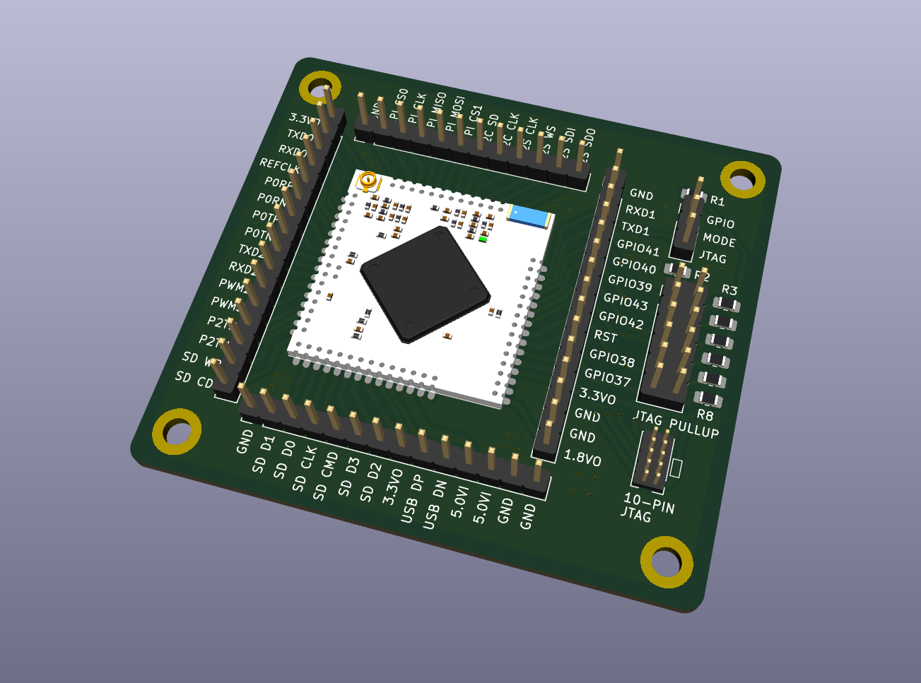
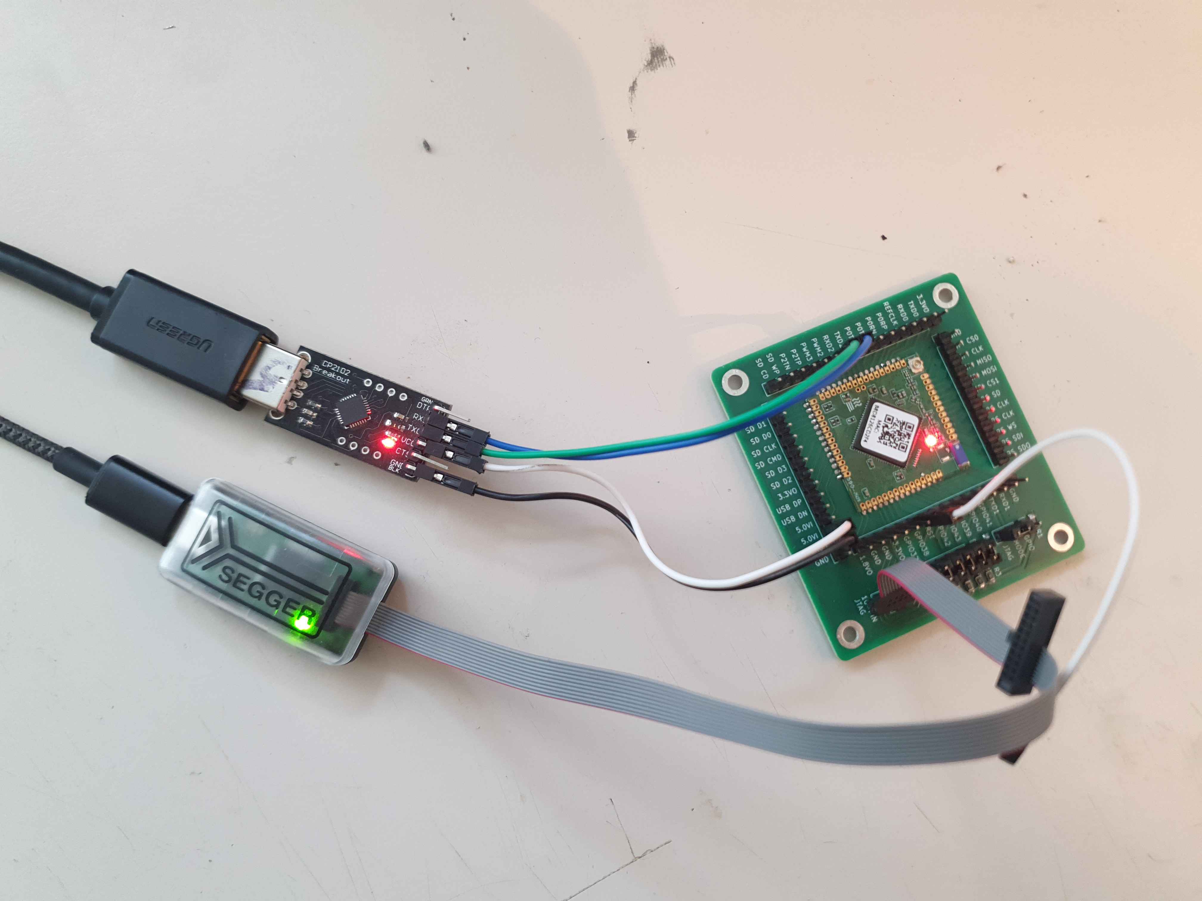
J6 is a 2×5 1.27 mm pitch header wired to the standard 9-pin ARM Cortex debug connector used by the J-Link EDU Mini.
| Pin | Signal | Notes |
|---|---|---|
| 1 | +3V3 | VTref - sense only, do not power board from here |
| 2 | JTAG_TMS | MT7628 GPIO41 / EPHY_LED2_N_JTMS |
| 3 | GND | |
| 4 | JTAG_CLK | MT7628 GPIO40 / EPHY_LED3_N_JTCLK |
| 5 | GND | |
| 6 | JTAG_TDO | MT7628 GPIO43 / EPHY_LED0_N_JTDO |
| 7 | NC | KEY position - no pin on J-Link EDU Mini |
| 8 | JTAG_TDI | MT7628 GPIO42 / EPHY_LED1_N_JTDI |
| 9 | JTAG_TRST | MT7628 GPIO39 / EPHY_LED4_N_JTRST_N |
| 10 | RESET | MT7628 pin 138 / PORST_N (system reset, active-low) |
The J-Link EDU Mini uses the 9-pin Cortex-M variant of the connector, not the full 20-pin JTAG header:
JTRST_N (GPIO39).PORST_N.WDT_RST_N (GPIO37 / MT7628 pin 137) appears adjacent to PORST_N and JTRST_N on the VoCore2 right-side connector and was considered for pin 9.
The vendor's JTAG how-to uses WDT_RST_N as "TRST" in their OpenOCD sysfsgpio config. This works because their setup is one VoCore2 bit-banging GPIOs to debug another - the host just needs two GPIO outputs to toggle, and driving WDT_RST_N low from an external GPIO triggers a full chip reset which also resets the JTAG TAP. OpenOCD's sysfsgpio driver doesn't care what hardware the signal is physically connected to; it just toggles the GPIO.
The J-Link is a hardware probe that follows the ARM Cortex debug connector spec strictly: pin 9 (nTRST) is driven by J-Link silicon to reset only the JTAG TAP, and the probe asserts and de-asserts it independently during normal debug sessions. If pin 9 connects to WDT_RST_N, every nTRST assertion by the J-Link triggers a full watchdog system reset, killing the debug session. WDT_RST_N is also a chip output when the watchdog fires, so the J-Link driving it creates a bus conflict. JTRST_N (GPIO39) resets only the TAP and has no output driver conflict.
All five JTAG signals (TMS, TCK, TDI, TDO, TRST) need pull-ups to 3V3. RESET (PORST_N) does not need external pull-ups from the breakout.
OpenOCD requires third-party target scripts for the MT7628 - the standard script directory does not include this SoC. Clone mtk-openwrt/openocd-scripts and point OPENOCD_SCRIPTS at it. This provides mt7628.cfg along with the cpu_pll_init and dram_init TCL helpers needed to bring up the PLL and DDR2 after halting the CPU via JTAG.
openocd -f interface/jlink.cfg \
        -c "transport select jtag" \
        -c "adapter speed 100" \
        -c "reset_config trst_and_srst separate srst_nogate connect_assert_srst" \
        -f mt7628.cfg \
        -c "init" \
        -c "reset halt" \
        -c "wait_halt 10000"
adapter speed 100 - the MT7628 PLL is not running at reset; the JTAG clock source is the raw 40 MHz crystal. 100 kHz is conservative enough to be reliable in that window.
reset_config trst_and_srst separate srst_nogate connect_assert_srst - connect_assert_srst holds SRST (PORST_N) asserted when OpenOCD first connects, keeping the system in reset while the JTAG TAP initializes. srst_nogate keeps TCK running during SRST so OpenOCD can set the EJTAGBOOT instruction before releasing SRST. When SRST releases, the CPU starts with EJTAGBOOT active, enters the EJTAG debug ROM, and halts before its first instruction.
MT7628 GPIO13 / TXD1 (VoCore2 pad PR01) is sampled at power-on reset to determine whether the EPHY_LED pins (GPIO39–GPIO43) operate as Ethernet LEDs or as the JTAG interface.
TXD1 at boot | Mode |
|---|---|
| HIGH (3V3) | Normal - EPHY_LED pins as Ethernet LEDs, JTAG disabled |
| LOW (GND) | JTAG enabled - EPHY_LED pins as TMS/TCK/TDI/TDO/TRST |
JP1 is a 3-pin jumper with 4.7 kΩ resistors on both options:
JP1 position | TXD1 | JTAG |
|---|---|---|
| 1-2 ("GPIO", default) | HIGH via R1 (4K7 to +3V3) | Disabled |
| 2-3 ("JTAG") | LOW via R2 (4K7 to GND) | Enabled |
Warning: JTAG mode breaks SD/eMMC on the EPHY pads.TXD1 low (DBG_JTAG_MODE=0) does more than swap the EPHY_LED pins to JTAG, it puts the whole EPHY block into JTAG/debug state. If SD/eMMC is then muxed onto the EPHY pads ("IoT" mode, e.g. VoCore2's SD lines), the card stops responding. This is a hardware mutual-exclusion, not a software setting, JTAG and SD-on-EPHY cannot be used at the same time. Change the jumper after flashing to put the board into normal operation.
The stock VoCore2 module has R9 populated (pull-up, 4.7 kΩ to 3V3) which holds TXD1 high and disables JTAG. To use JTAG:
R9 from the VoCore2 module (eliminates the internal pull-up).JP to position 2-3 on the breakout.The breakout JP then has sole control over TXD1 with no internal resistor fighting it. Leaving R9 on the module while setting JP to 2-3 creates a voltage divider (~1.65 V, undefined logic level).
The original VoCore2 JTAG how-to describes moving R9 to the R6 footprint (a pull-down). With R9 removed entirely and JP at 2-3, the effect is the same.
Gerber files are in the gerber/ directory and can be sent directly to a PCB manufacturer.
Before assembly, it is recommended to bake the VoCore2 module at 120 °C for at least 12 hours to drive out moisture. However it works just as well without.
The VoCore2 module must be reflowed using hot air, do not use a soldering iron. The DDR2 on the module is ESD-sensitive and iron leakage current can cause permanent damage. Reflow temperature must not exceed 260 °C for more than 10 seconds.
The resistors can be reflowed together with the VoCore2 module or soldered normally with an iron. The through-hole pin headers are soldered normally. Take special care with the JTAG header (J6): it uses a 1.27 mm pitch fine-pitch header where adjacent pins are easy to bridge accidentally. Inspect with a loupe or microscope after soldering.
| Qty | Value | Footprint | References |
|---|---|---|---|
| 5 | 10K | Resistor_SMD:R_0805_2012Metric_Pad1.20x1.40mm_HandSolder | R3, R4, R5, R6, R7 |
| 4 | MountingHole_Pad | MountingHole:MountingHole_3.2mm_M3_DIN965_Pad | H1, H2, H3, H4 |
| 2 | 4K7 | Resistor_SMD:R_0805_2012Metric_Pad1.20x1.40mm_HandSolder | R1, R2 |
| 1 | Conn_01x12_Socket | Connector_PinHeader_2.54mm:PinHeader_1x12_P2.54mm_Vertical | J2 |
| 1 | Conn_01x14_Socket | Connector_PinHeader_2.54mm:PinHeader_1x14_P2.54mm_Vertical | J3 |
| 1 | Conn_01x15_Socket | Connector_PinHeader_2.54mm:PinHeader_1x15_P2.54mm_Vertical | J4 |
| 1 | Conn_01x16_Socket | Connector_PinHeader_2.54mm:PinHeader_1x16_P2.54mm_Vertical | J1 |
| 1 | Conn_02x05_Odd_Even | Connector_PinHeader_1.27mm:PinHeader_2x05_P1.27mm_Vertical | J6 |
| 1 | Conn_02x05_Odd_Even | Connector_PinHeader_2.54mm:PinHeader_2x05_P2.54mm_Vertical | J5 |
| 1 | Jumper_3_Bridged12 | Connector_PinHeader_2.54mm:PinHeader_1x03_P2.54mm_Vertical | JP1 |
| 1 | VOCORE2-SMT | vocore2-lib:VOCORE2-SMT | U1 |

hackclub/OnBoard
💡 Join 1,000 teenagers and make your first PCB with a $100 grant!

polpo/picogus
Emulation of ISA sound cards and CD-ROM on Raspberry Pi Pico (GUS, SB/Adlib, MPU-401, Tandy, CMS, Panasonic CD-ROM) with USB mouse/joystick support


nkitanov/iaq_board
IAQ Board is a DIY (Do-It-Yourself) device for measuring internal air quality


Ardumower/ardumower
Develop an open source robotic lawn mower (HW+SW reference platform)

zmaker/arduino_cookbook
gli sketch del nuovo progetto Arduino Cookbook e dei video di YouTube
It measures 65.5 × 59 mm and has 2 copper layers, 1.64 mm thick.
19 parts. The full list of its parts is on this page, with links to each part's symbol and footprint where PCBKit's library has them.
From the StarGate01/vocore2-breakout repository on GitHub, at the commit this page was made from: the board is vocore2-breakout/vocore2-breakout.kicad_pcb and its schematic vocore2-breakout/vocore2-breakout.kicad_sch. PCBKit opens the board in the browser, with nothing to install.
Its repository publishes it under the MIT licence: you may reuse it on that licence's terms (keep the author's notice, and for a copyleft licence share your changes alike).