

4 layers149.9 × 74.2 mm
BCD-0o27
petnica-rac-seminari/BCD-0o27-Tetris
The BalcCon Cyberdeck 0o27 (BCD-0o27) comes with a development framework that makes it easier to add functionality to the cyberdeck.
142 parts1

 SomethingFourier/FPGA-Musical-Synth1
A musical synthesizer that generates and outputs I2S audio with an FPGA
Synthboard is an open-source printed circuit board by SomethingFourier, from the SomethingFourier/FPGA-Musical-Synth repository on GitHub. It is a 2-layer board of 133.4 × 55.2 mm with 51 parts on 38 nets, routed with 525 tracks and 210 vias.
It is built around the 74HC165D and WS2812B. Its parts include 12 resistors, 12 diodes, 12 switches, 6 capacitors and 3 connectors. It belongs with the audio and music and fPGA and programmable logic boards of this library.
A musical synthesizer based on the iCE40 FPGA that outputs I2S audio.
Video demonstration of sine wave synth: https://youtu.be/_ejQGvuSiI
The PCBs have been ordered and delivered! All that remains for that part is to bring the boards up and perform PCBA.
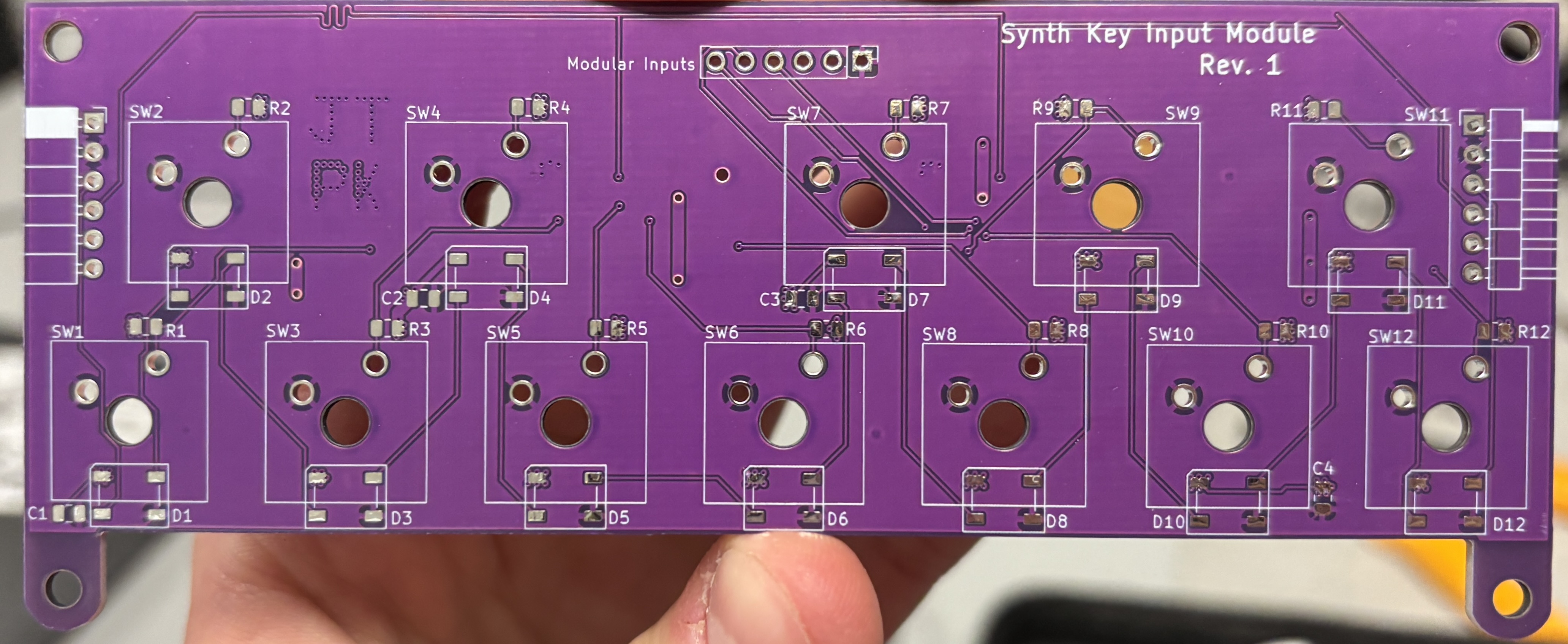
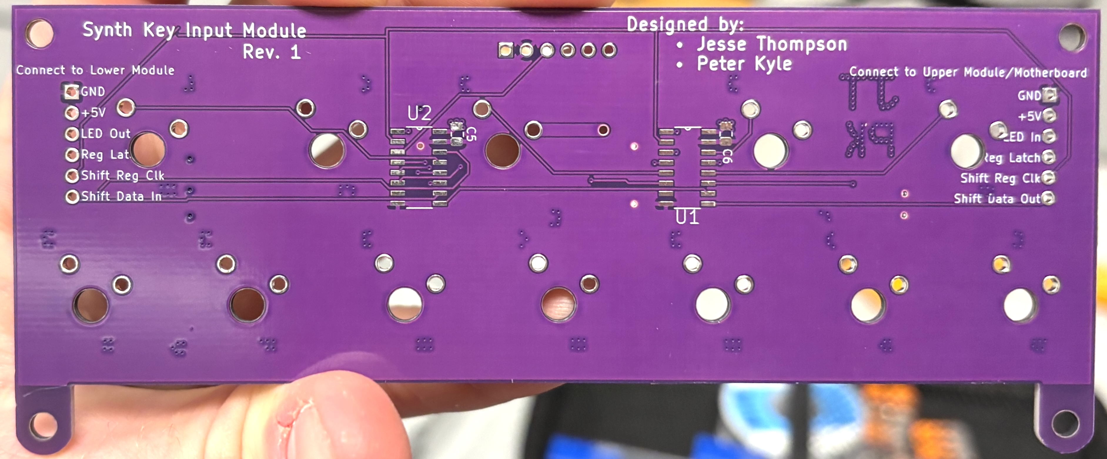
The PCB for the input module has been completed. Each module represents 1 octave (12 keys). We decided to use shift registers to read key input in parallel and send out that data to the FPGA as serial (PISO). This provides a few advantages over other methods of key input:
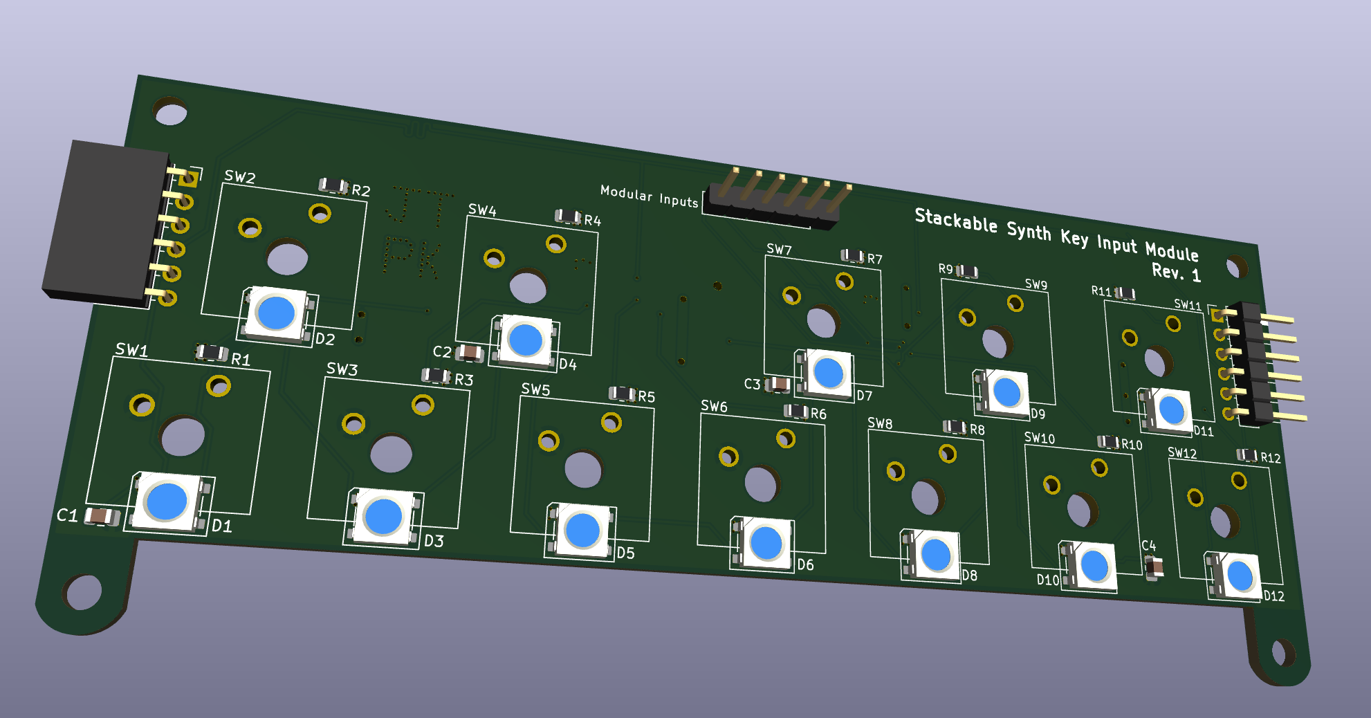
The order for this PCB will be placed within a week or two; I am waiting to order it alongside PCBs for a class I'm currently taking. Because this PCB was designed to daisy-chain duplicates together, it was not designed with a place for an FPGA or the development board; that will be a separate module.
Video demonstration of sine wave synth: https://youtu.be/_ejQGvuSiI8
The synth now makes sine waves by the Numerically-Controlled Oscillator (NCO)! This opens the door to make any kind of wave we want just by updating the ROMs. Additionally, a multi-clock cycle multiplication algorithm has been implemented to save space on the FPGA and take advantage of the 512 master clock cycles between one sample and the next.
Video demonstration of square wave synth: https://youtu.be/o0nXdgJRZlI
The wave_period_selector method of synthesis used is described by this process:
wave_period_selector sends the half-period of the frequency (musical note) associated with the key pressed to i2s_transmitter. i2s_transmitter sends a square wave via I2S that oscillates every half-period (the one sent to it by wave_period_selector) to an I2S DAC. This generates a square wave at the desired frequency.
The square wave synth only supports one key press at a time. If multiple keys are pressed, the key that gets checked first in wave_period_selector is the note that gets played. Further, due to the nature of this synthesis, this only supports square waves.
OSS-CAD-SUITE is being used for iCE40 synthesis, Place-and-Route, as well as packing.
Icarus Verilog (iverilog) is being used for test bench simulation and other debugging. Verilator may replace icarus if it is decided that it is superior for testbenching this project's verilog modules.
The FPGA was programmed in SystemVerilog.
| Qty | Value | Footprint | References |
|---|---|---|---|
| 12 | 11k | Resistor_SMD:R_0805_2012Metric | R1, R2, R3, R4, R5, R6, R7, R8, R9, R10, R11, R12 |
| 12 | SW_Push | Button_Switch_Keyboard:SW_Cherry_MX_1.00u_Plate | SW1, SW2, SW3, SW4, SW5, SW6, SW7, SW8, SW9, SW10, SW11, SW12 |
| 12 | WS2812B | LED_SMD:LED_WS2812B_PLCC4_5.0x5.0mm_P3.2mm | D1, D2, D3, D4, D5, D6, D7, D8, D9, D10, D11, D12 |
| 6 | 0.1 µF | Capacitor_SMD:C_0805_2012Metric | C1, C2, C3, C4, C5, C6 |
| 4 | MountingHole | MountingHole:MountingHole_3.2mm_M3 | H1, H2, H3, H4 |
| 2 | 74HC165 | 74HC165D_653:SOIC127P600X175-16N | U1, U2 |
| 1 | Connect to Lower Module | Connector_PinHeader_2.54mm:PinHeader_1x06_P2.54mm_Horizontal | J2 |
| 1 | Connect to Upper Module/Motherboard | Connector_PinSocket_2.54mm:PinSocket_1x06_P2.54mm_Horizontal | J1 |
| 1 | Modular Inputs | Connector_PinHeader_2.54mm:PinHeader_1x06_P2.54mm_Vertical | J3 |
petnica-rac-seminari/BCD-0o27-Tetris
The BalcCon Cyberdeck 0o27 (BCD-0o27) comes with a development framework that makes it easier to add functionality to the cyberdeck.

Alen1132011/Smart-chess-board
A physical chess board that can detect the position of chess pieces in real time using Hall effect sensors and provide visual feedback through RGB LEDs.


devices-lab/solderbit-gamepad
Learn-to-solder kit for the BBC micro:bit

koko69420/HomeBus
Hard wired home automation, based on a RSICV MCU and RS-422 communication protocol

It measures 133.4 × 55.2 mm and has 2 copper layers, 1.6 mm thick.
51 parts, built around the 74HC165D and WS2812B. The full list of its parts is on this page, with links to each part's symbol and footprint where PCBKit's library has them.
From the SomethingFourier/FPGA-Musical-Synth repository on GitHub, at the commit this page was made from: the board is kicad/key_input_module/rev_1/synthboard.kicad_pcb and its schematic kicad/key_input_module/rev_1/synthboard.kicad_sch. PCBKit opens the board in the browser, with nothing to install.
Its repository states no licence, so its author keeps all rights: ask SomethingFourier before reusing the design.