2 layers182.9 × 172.7 mm
 ShadabMizan/LED-Matrix1
Designing and Coding an LED Display from Scratch
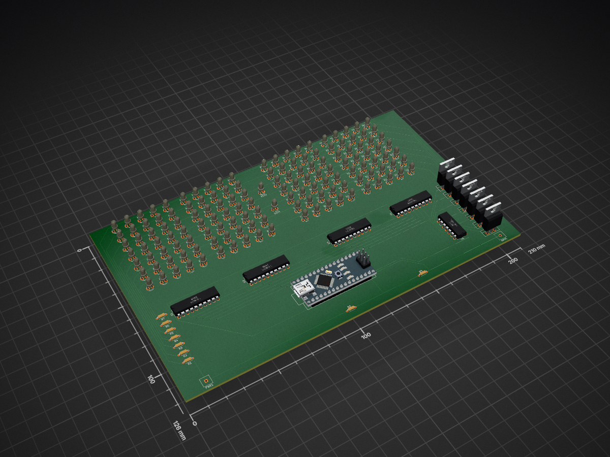
LED Design is an open-source printed circuit board by ShadabMizan, from the ShadabMizan/LED-Matrix repository on GitHub. It is a 2-layer board of 210 × 126 mm with 166 parts on 91 nets, routed with 718 tracks and 20 vias.
It is built around the 74LS573PC, 74HC164 and IR204-A-L. Its parts include 142 diodes, 9 resistors, 7 transistors and 5 ICs. It belongs with the AVR (ATmega, ATtiny) boards of this library.


This was a personal project I committed to during my first year as an engineering student at SFU. In this repository, you can find both the code that controls the matrix display as well as CAD files for the electronic schematics, as well as Gerber files for the PCB. I began this project by following tutorials I found online, but after a mistake ordering the N-Channel MOSFETs instead of P-Channel ones, the tutorial's instructions could no longer apply. Thus began my even deeper dive into how the electronics and techniques behind manning an LED display worked, and I can proudly say I learned a lot from this experience.
Breadboard setup used for the prototyping the hardware.
Debugging a 3x3 matrix to try and display an X.
Final PCB.
My design for the Matrix uses 7 rows of 20 LEDs, and to turn on LEDs that we want to display a certain pattern of lights, we employ a technique called scanning, where there is only ever 1 row of LEDs that are supplied power at any time, but since we cycle through them so fast, to our eyes it seems as a static display. Powering up to 20 LEDs sufficiently can take a bit of voltage, so to switch quickly between powering different rows, I used N-Channel MOSFETs placed by GND at the end of each LED row to control whether current can get to GND through the MOSFET (LED is OFF) or if current cannot get through the MOSFET (LED is ON). To control which Columns were connected to GND, each column was connected to an output pin of an IC, where a HIGH signal would not connect that LED to GND, but a LOW signal would.
In the code, I've implemented some classes to organize which objects control what features, as well as make the code scalable and simple in the main function. The Matrix class is the important one which controls the communication between the arduino and ICs, essentially bringing life to the PCB. As I've mentioned, scanning quickly through rows is essential for the LED Display to work without flickering, and to optimize processing speeds and time I've implemented functions that work in place with data thats stored, thus cutting time losses of copying data structures every time the loop runs. Furthermore, I've implemented bit operations to work with states within a byte, thus I can save the state a 35 LED cell should have with only 7 bytes for its 7 rows, rather than 35 bytes. The other class implemented is the Timer class, which simply allows the user to set up a timer which can be seen in the LED display.
| Qty | Value | Footprint | References |
|---|---|---|---|
| 142 | IR204A | LED_THT:LED_D3.0mm_Clear | D1, D10, D11, D100, D101, D102, D103, D104, D105, D106, D107, D108, D109, D110, D111, D112 +126 |
| 7 | 2.0k | Resistor_THT:R_Axial_DIN0204_L3.6mm_D1.6mm_P5.08mm_Horizontal | R1, R2, R3, R4, R5, R6, R7 |
| 7 | NMOS | Package_TO_SOT_THT:TO-220-3_Vertical | Q1, Q2, Q3, Q4, Q5, Q6, Q7 |
| 4 | 74LS573 | Package_DIP:DIP-20_W7.62mm | U1, U2, U3, U4 |
| 2 | 1.0k | Resistor_THT:R_Axial_DIN0204_L3.6mm_D1.6mm_P5.08mm_Horizontal | R8, R9 |
| 1 | 24V, 0.160A | TerminalBlock_MetzConnect:TerminalBlock_MetzConnect_360271_1x01_Horizontal_ScrewM3.0_Boxed | PWR1 |
| 1 | 74HC164 | Package_DIP:DIP-14_W7.62mm | U5 |
| 1 | Arduino_Nano_v2.x | Module:Arduino_Nano | A1 |
| 1 | ~ | TerminalBlock_MetzConnect:TerminalBlock_MetzConnect_360271_1x01_Horizontal_ScrewM3.0_Boxed | GND1 |


robfinch/Cores
Cores ===== RTF's Cores Use at your own risk. Welcome to my galaxy of cores. Contained in the directories are IP cores, source code for digital circuits.


jtflanagan/AppleTini
Teeny 4.1-based multifunctional Apple II peripheral card
It measures 210 × 126 mm and has 2 copper layers, 1.6 mm thick.
166 parts, built around the 74LS573PC, 74HC164 and IR204-A-L. The full list of its parts is on this page, with links to each part's symbol and footprint where PCBKit's library has them.
From the ShadabMizan/LED-Matrix repository on GitHub, at the commit this page was made from: the board is LED-Design/LED-Design.kicad_pcb and its schematic LED-Design/LED-Design.kicad_sch. PCBKit opens the board in the browser, with nothing to install.
Its repository states no licence, so its author keeps all rights: ask ShadabMizan before reusing the design.