

2 layers102 × 21.8 mm
 SgtLexington/Buzzer-System
All the files necessary for the project.
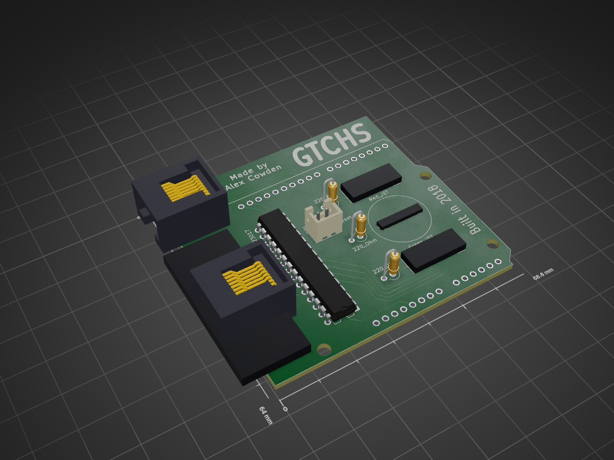
Main Board gerber is an open-source printed circuit board by SgtLexington, from the SgtLexington/Buzzer-System repository on GitHub. It is a 2-layer board of 68.6 × 64 mm with 11 parts on 55 nets, routed with 90 tracks and 0 vias.
It is built around the RJ45 and MCP23017-E/SS. It belongs with the AVR (ATmega, ATtiny) boards of this library.
The way that academic competitions work is this: to get points, a player must "buzz in" while or after a question has been answered. Then, the player must answer the question correctly. The moderator will take whoever buzzes in first, so it is very important to practice the buzzing motion to do well. My team has lots of talent, but we are always at a disadvantage when we go to competitions becausewe never practice with the equipment that we use at those competions. Usually at practices, to buzz in, we just hit the desk, while at competions there is a handheld buzzer system where the button to buzz in must be activated by a thumb motion. Naturally, we are slightly outperformed in this category by teams that do practice with a real buzzer system. The solution is simple: just buy a buzzer system like the ones at the competitions. However, decent quality buzzer systems are expensive. Some of the highest quality systems are $200-$300, and my school simply cannot afford something like that. Given that, I decided to make a buzzer system for us. Not only does having a buzzer system help the team practice better, but if we bring our own buzzer system to a competition, we get a discount on the entry fee. Here is the finished system: [insert pic here] Prototyping Protoboards Solidworks The Main Box: Arduino Program KiCad and PCB Solidworks box & lid The Team Boxes: KiCad and PCB Solidworks box & lid The Buzzers: Solidworks MicroUSB & button housings
| Qty | Value | Footprint | References |
|---|---|---|---|
| 3 | R | Resistors_THT:R_Axial_DIN0309_L9.0mm_D3.2mm_P2.54mm_Vertical | 220_Ohm, 220_Ohm, 220_Ohm |
| 2 | Conn_01x05 | Connectors_JST:JST_XH_B05B-XH-A_05x2.50mm_Straight | Green_JST, Red_JST |
| 2 | RJ45 | Connectors:RJ45_8 | Green1, Red1 |
| 1 | Arduino_Uno_Shield | Arduino:Arduino_Uno_Shield | ARD1 |
| 1 | Buzzer | Buzzers_Beepers:BUZZER | Sound1 |
| 1 | Conn_01x02 | Connectors_JST:JST_XH_B02B-XH-A_02x2.50mm_Straight | Reset_JST |
| 1 | MCP23017 | Housings_DIP:DIP-28_W7.62mm | IOexpander1 |


RobertPHeller/2ndGenLocoControlStand
Model 2nd Generation Diesel Locomotive Control Stand

sq9fk/ant-sw-2x6
Firmware sterownika przełącznika antenowego 6 anten × 2 TRX oparty na projekcie RemoteQTH 6×2 Antenna Controller (oryginał OK1HRA, rev 0.3), zmodyfikowany przez SQ9FK na potrzeby stacji SP9PDF.

RobertPHeller/RPi-RRCircuits
A collection of circuit designs for various MCUs, not just Raspberry Pis relating to Model Railroading

mattchesters/zmk-apple-desktop-bus-keyboard
ZMK shield for Apple Desktop Bus Keyboard

ZeroPhone/ZeroPhone-PCBs
PCB files for ZeroPhone - for gerbers and schematics, go to "Releases" tab!

ktec-hq/ErgoDone
ErgoDox using pro micro. Original work by Dox. Brainhole association present
It measures 68.6 × 64 mm and has 2 copper layers, 1.6 mm thick.
11 parts, built around the RJ45 and MCP23017-E/SS. The full list of its parts is on this page, with links to each part's symbol and footprint where PCBKit's library has them.
From the SgtLexington/Buzzer-System repository on GitHub, at the commit this page was made from: the board is Circuitry/Main Board gerber/Main Board.kicad_pcb. PCBKit opens the board in the browser, with nothing to install.
Its repository states no licence, so its author keeps all rights: ask SgtLexington before reusing the design.