2 layers338.7 × 107.7 mm

 Seequa-Computer-Preservation/chameleon_ramplus
A reproduction of the original Chameleon RAMPlus board
Chameleon ram card is an open-source printed circuit board by Seequa-Computer-Preservation, from the Seequa-Computer-Preservation/chameleon_ramplus repository on GitHub. It is a 2-layer board of 206 × 145 mm with 165 parts on 166 nets, routed with 6,427 tracks and 314 vias.
It is built around the PAL16R4-7JC, 74LS245SC and 74F157PC, with the SN74LS280N among its other parts. Its parts include 66 capacitors, 64 ICs, 8 resistors, 5 connectors and 1 crystal. It belongs with the NXP (LPC, Kinetis, i.MX RT) boards of this library.


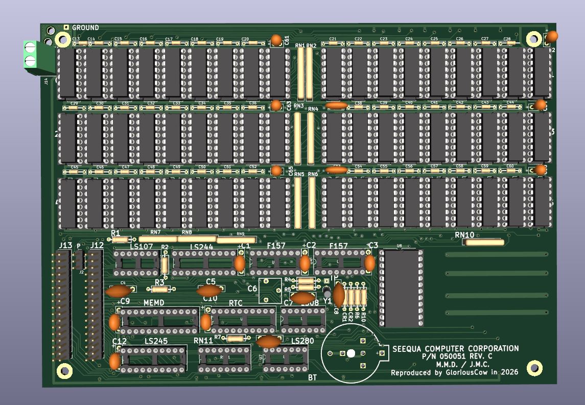
This repository contains a KiCad project that reproduces the Seequa Chameleon RAMPlus expansion board, P/N 050051 REV C.
This board has not yet been ordered and tested, but it does pass all design and electrical rule checks. If you want to be the first to try it, be my guest, but I make no guarantees there will be no bodges required. There almost certainly will be some issue I have missed.
This board will not function without the required PAL chips - so you will need a source for those. I hope to eventually figure out how to replace the PALs with a GAL or some other kind of PLD.
UART Option: The current version of this board does not include the 8250 UART option found on some versions of the RAMPlus card.
Power Connections: A screw terminal footprint has been added for power wiring if you'd like your board to be removable without fishing the molex plug out from the guts of your Chameleon, or if your power leads have broken off or otherwise detached.
I am not sure what screw terminals will work given the tight clearances involved - when this has been verified I will update this README.
The original strain relief pass-through holes and pads are still present if you would prefer to use them, and have been reinforced with plated through-holes and stitched copper fills for improved durability.
Parity RAM Jumper: A new jumper J2 has been introduced. This allows configuration to skip populating the parity RAM chips if parity checking is not required. Jumper pins 1&2 to enable parity, jumper pins 2&3 to disable it. This is independent of any software parity control.
Minor improvements:
The authoritative BOM should ideally be generated in KiCad, but RAMPlus_BOM.csv has been exported for your reference. If you do plan to order one of these boards, please get in touch first to make sure there are no last minute updates that have not been reflected here.
Some components may be difficult to find. The particular type of three-legged trimmer capacitor used to adjust the RTC crystal timing is no longer manufactured. Surplus trimmer caps are still available. One site selling them is here (no afffiliation or recommendation implied, caveat emptor):
https://www.surplussales.com/items/106928/ceramic-trimmer-capacitor/
The MM58167 RTC chip can regularly be found on eBay.
The board may be able to use 4164 DRAMs with some tweaks to capacitor values - Seequa populated the board with 4564s, which you can find on eBay or in bulk here: https://www.electronicsurplus.com/mostek-mk4564n15-ic-memory-dram-64k-x-1 https://www.surplussales.com/items/147639/mostek-memory-dip/
The RAMPlus card includes two new PALs, a DRAM decoder for the three new RAM banks, and an address decoder / control PAL for the RTC. These have yet to be dumped, but will be in time.
The RAMPlus w/ Serial option has a third PAL, SERB, to decode for the 8250.
| Qty | Value | Footprint | References |
|---|---|---|---|
| 54 | MK4564 | seequa_footprints:DIP-16_W7.62mm_MK4164N_Socketed_With_Chip | U11, U12, U13, U14, U15, U16, U17, U18, U19, U20, U21, U22, U23, U24, U25, U26 +38 |
| 44 | 0.1µF | seequa_footprints:C_Seequa_MLCC_Bypass_P7.62mm | C14, C15, C16, C17, C18, C19, C20, C21, C22, C23, C24, C25, C26, C27, C29, C30 +28 |
| 6 | 0.1uF | seequa_footprints:C_Seequa_Dipped_Tantalum_P7.50 | C1, C2, C3, C9, C10, C12 |
| 6 | 0.1µF | seequa_footprints:C_Seequa_Bypass_2.54mm | C61, C62, C63, C64, C65, C66 |
| 6 | 330Ω | seequa_footprints:R_Array_SIP8 | RN1, RN2, RN3, RN4, RN5, RN6 |
| 3 | 510Ω | seequa_footprints:R_Seequa_P10_7.5mm_Box | R2, R3, R7 |
| 3 | MountingHole_Pad | seequa_footprints:MountingHole_3.2mm_M3_Pad_TopBottom | H1, H2, H3 |
| 2 | 0.1µF | seequa_footprints:C_Seequa_MLCC_Bypass_P3.7mm | C13, C28 |
| 2 | 0.1µF | seequa_footprints:C_Seequa_MLCC_Bypass_P5mm | C37, C53 |
| 2 | 1N4148 | seequa_footprints:R_Seequa_P10_7.5mm_Box | CR1, CR2 |
| 2 | 330Ω | seequa_footprints:R_Array_SIP6_Compact | RN7, RN8 |
| 2 | 39pF | seequa_footprints:C_Seequa_Disc_P7.50mm | C4, C5 |
| 2 | 74F157 | seequa_footprints:DIP-16_W7.62mm_Socket | U3, U4 |
| 2 | Strain Relief | seequa_footprints:StrainRelief_LoopHole_2.7mm_PTH | H5, H6 |
| 1 | 0.1µF | seequa_footprints:C_Seequa_Disc_P7.50mm | C8 |
| 1 | 1.6MΩ | seequa_footprints:R_Seequa_P10_7.5mm_Box | R6 |
| 1 | 180Ω | seequa_footprints:DIP-16_W7.62mm_Socket | RN11 |
| 1 | 1MΩ | seequa_footprints:R_Seequa_P10_7.5mm_Box | R4 |
| 1 | 200kΩ | seequa_footprints:R_Seequa_P10_7.5mm_Box | R5 |
| 1 | 20pF | seequa_footprints:C_Seequa_Dipped_Film_P7.50mm | C7 |
| 1 | 270Ω | seequa_footprints:R_Array_SIP6_Compact | RN9 |
| 1 | 2kΩ | seequa_footprints:R_Seequa_P10_7.5mm_Box | R10 |
| 1 | 300Ω | seequa_footprints:R_Seequa_P10_7.5mm_Box | R1 |
| 1 | 32.768 kHz | seequa_footprints:Crystal_AT310_D3.0mm_L10.0mm_Vertical | Y1 |
| 1 | 330Ω | seequa_footprints:R_Array_SIP6 | RN10 |
| 1 | 3V Lithium | seequa_footprints:Seequa_BatteryHolder_CR2032 | BT1 |
| 1 | 5.0 - 70.0pF | seequa_footprints:C_Seequa_Trimmer | C6 |
| 1 | 74LS08 | seequa_footprints:DIP-14_W7.62mm_Socket | U5 |
| 1 | 74LS107 | seequa_footprints:DIP-14_W7.62mm_Socket | U1 |
| 1 | 74LS244 | seequa_footprints:DIP-20_W7.62mm_Socket | U2 |
| 1 | 74LS245 | seequa_footprints:DIP-20_W7.62mm_Socket | U6 |
| 1 | 82pF* | seequa_footprints:C_Seequa_Disc_P7.50mm | C11 |
| 1 | Expansion Header J12 | seequa_footprints:PinHeader_2x17_P2.54mm_Vertical | J12 |
| 1 | Expansion Header J13 | seequa_footprints:PinHeader_2x17_P2.54mm_Vertical | J13 |
| 1 | Ground Solder Pad | seequa_footprints:Power_Pad_2.0x2.0mm | P3 |
| 1 | MM58167 | seequa_footprints:DIP-24_W15.24mm_Socketed_Chip | U8 |
| 1 | MountingHole | seequa_footprints:MountingHole_3.2mm_M3_Pad_TopBottom | H4 |
| 1 | PAL16R4 | seequa_footprints:DIP-20_W7.62mm_Socket | U10 |
| 1 | PAL20L10 | seequa_footprints:DIP-24_W7.62mm_Socket | U9 |
| 1 | PARITY | seequa_footprints:PinHeader_1x03_P2.54mm_Vertical | J2 |
| 1 | SN74LS280N | seequa_footprints:DIP-14_W7.62mm_Socket | U7 |
| 1 | Screw_Terminal_01x02 | seequa_footprints:TerminalBlock_Phoenix_MKDS-1,5-2-5.08_1x02_P5.08mm_Horizontal | J14 |
| 1 | TestPoint | seequa_footprints:TestPoint_THTPad_1.5x1.5mm_Drill0.7mm | TP1 |

skiselev/intel-wildcard-88-motherboard
An IBM PC/XT compatible motherboard utilizing the Intel Wildcard 88 module


54weasels/sun3_60
Notes on each section: - CPU - 68030 support left out entirely - 68881 in the schematics but left out of the PCB - MMU - U2001 which would be needed to support any video, either P4 or built-in not in the PCB - U314…

ronnyroy111/inboard386
Reverse engineered schematics, PCB and logic equations for the Intel 386/PC accelerator


SukkoPera/Raemixx500
Open Hardware Remake of the Commodore Amiga 500+ Mainboard

mudmin/AnotherMaker
This is where I will store code snippets for AnotherMaker Videos
It measures 206 × 145 mm and has 2 copper layers, 1.6 mm thick.
165 parts, built around the PAL16R4-7JC, 74LS245SC, 74F157PC and SN74LS280N. The full list of its parts is on this page, with links to each part's symbol and footprint where PCBKit's library has them.
From the Seequa-Computer-Preservation/chameleon_ramplus repository on GitHub, at the commit this page was made from: the board is kicad/chameleon_ram_card.kicad_pcb and its schematic kicad/bus.kicad_sch. PCBKit opens the board in the browser, with nothing to install.
Its repository states no licence, so its author keeps all rights: ask Seequa-Computer-Preservation before reusing the design.