Skip to the content
2 layers70 × 70 mmLight PCB, the printed circuit board in 3D

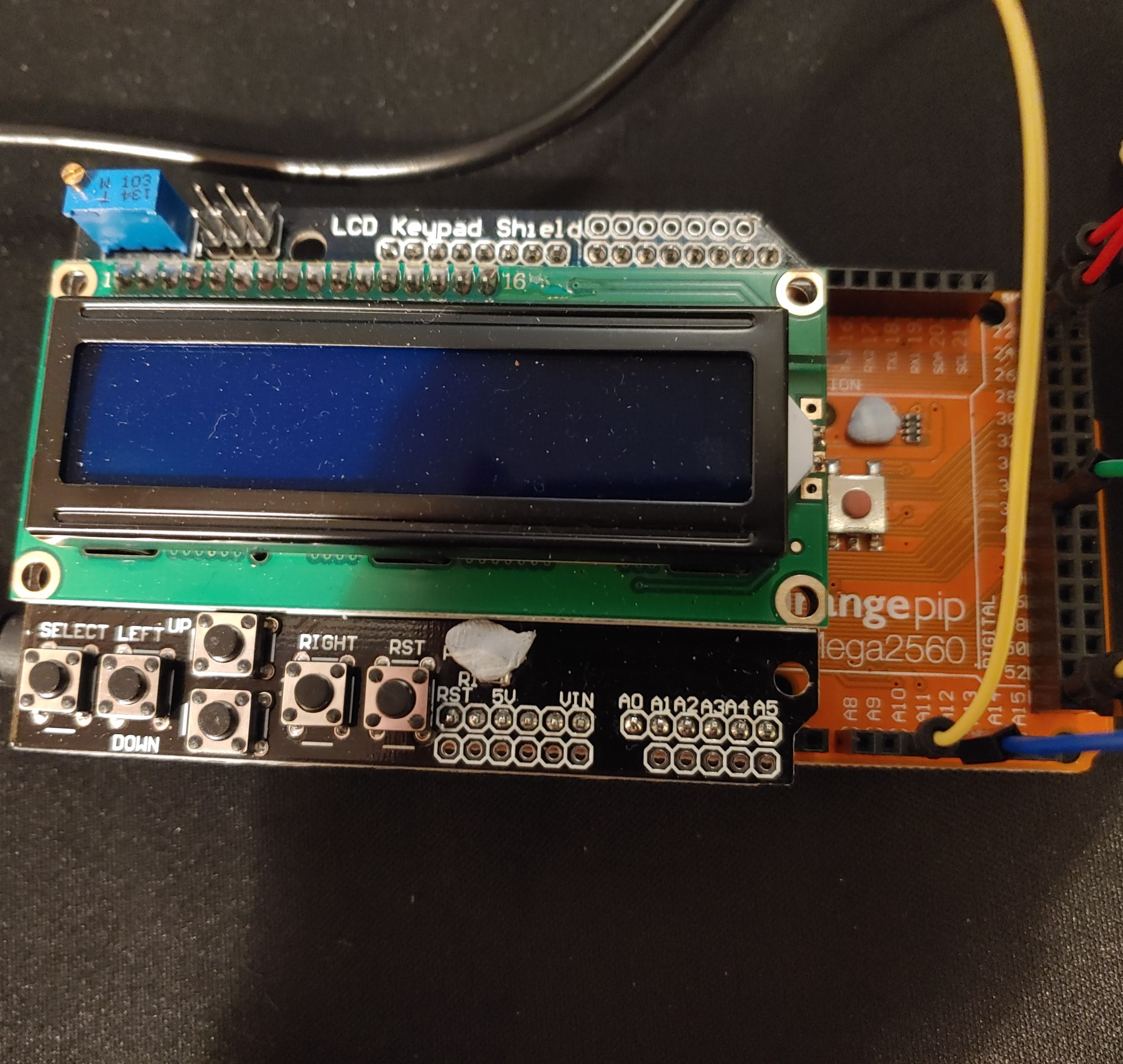
This is the third version of the "Sunrise Alarm Clock" project. The first version used an Arduino Mega and an LCD keypad shield. The second version used a Wemos D1 mini (ESP8266) and 0.96" OLED on a single custom PCB.

Size
70 × 70 mm
Copper layers
2
Thickness
1.6 mm
Parts
19
Nets
5
Pads
40
Tracks, vias
25, 1
Routed
Yes
KiCad
KiCad 7 (file 20221018)
Created
7 Sep 2023
Updated
25 Feb 2024

Overview

Light PCB is an open-source printed circuit board by SeanP2001, from the SeanP2001/Sunrise_Alarm_Clock_V3 repository on GitHub, published under the GPL-3.0 licence. It is a 2-layer board of 70 × 70 mm with 19 parts on 5 nets, routed with 25 tracks and 1 via.

Its parts include 16 diodes, 1 resistor, 1 transistor and 1 connector. It belongs with the lEDs and displays boards of this library.

README

README.md

Sunrise Alarm Clock V3

Table of Contents

Introduction

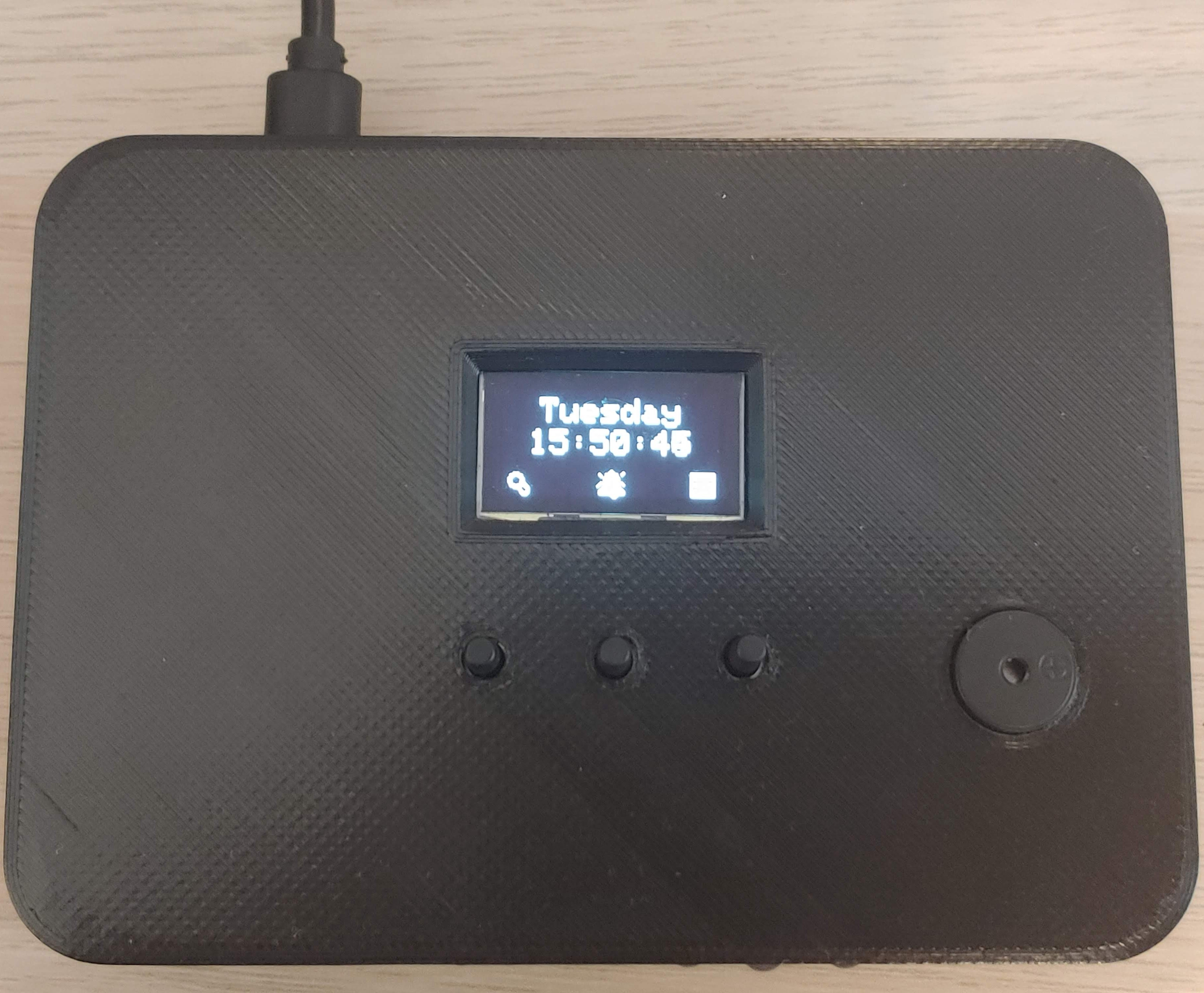
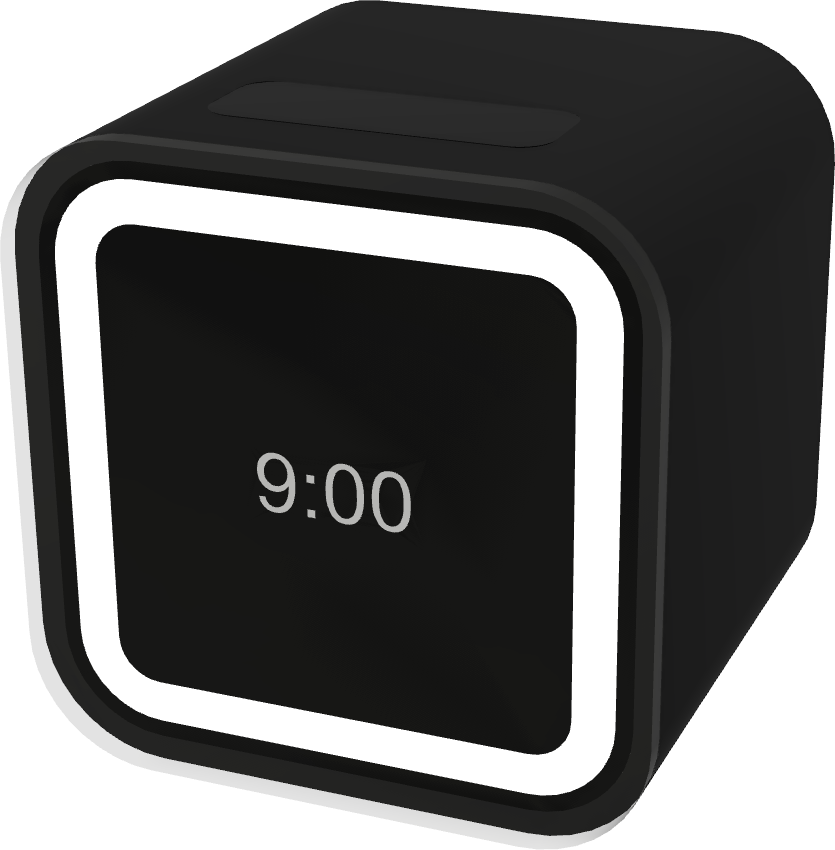
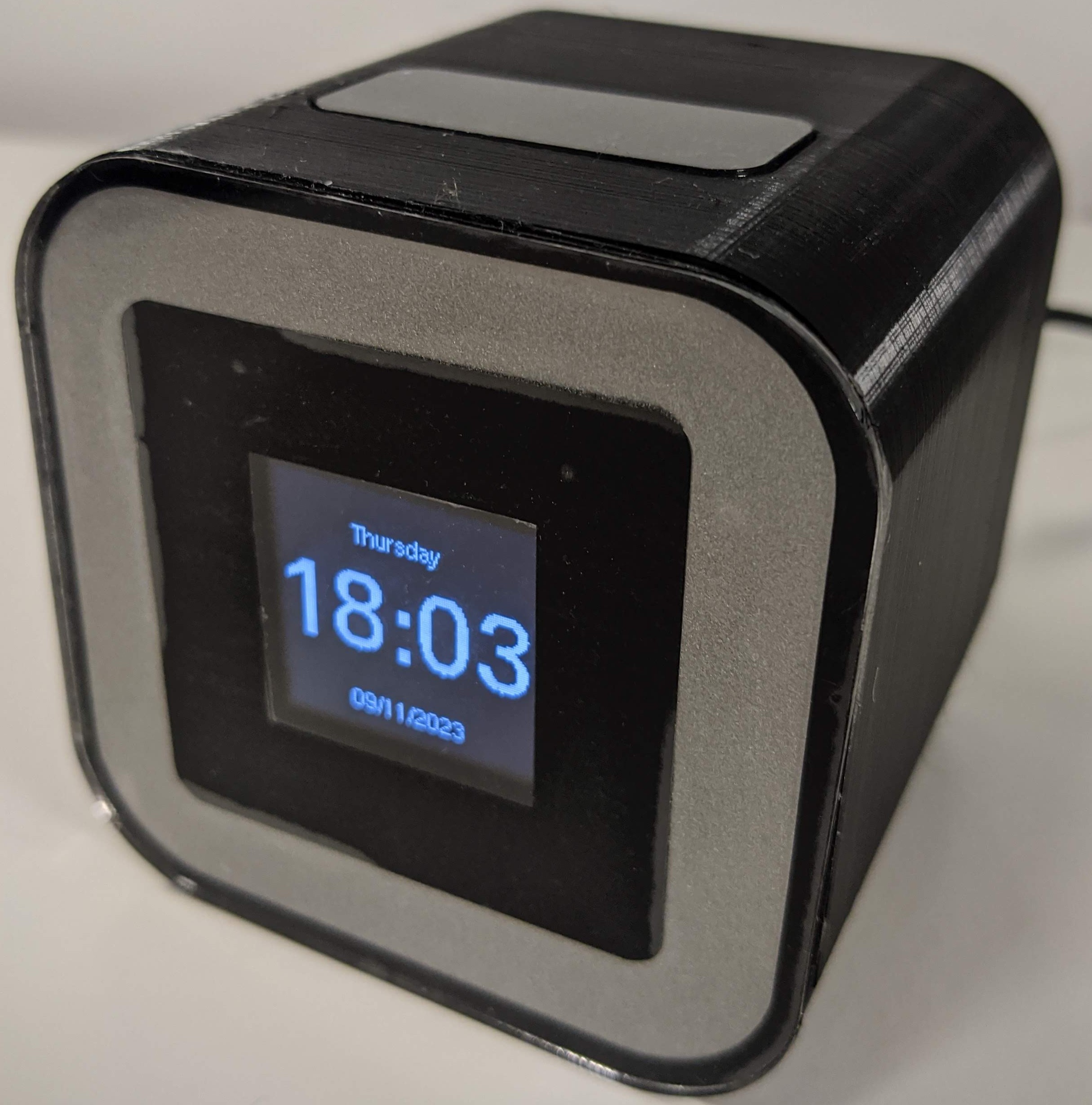
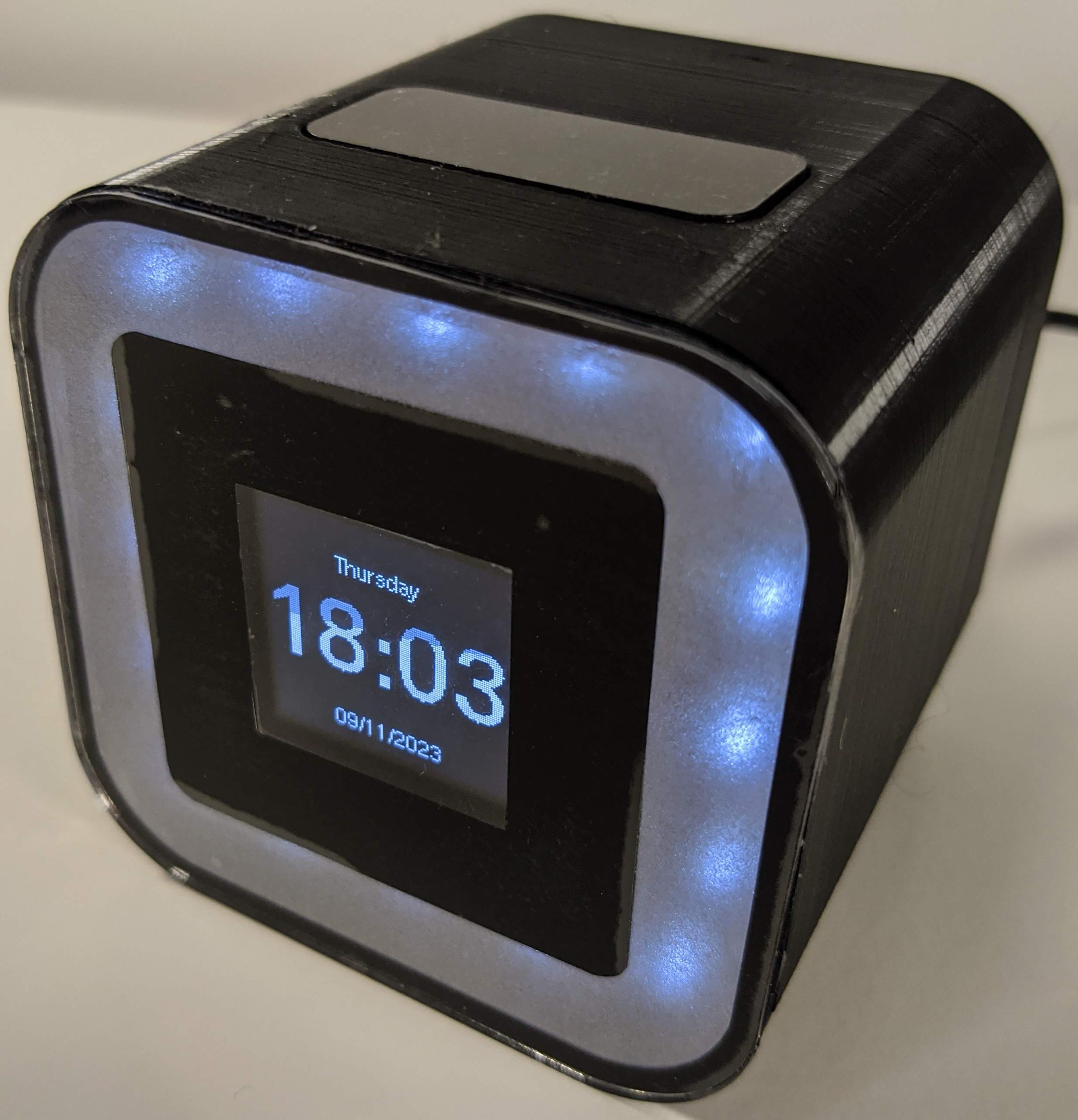
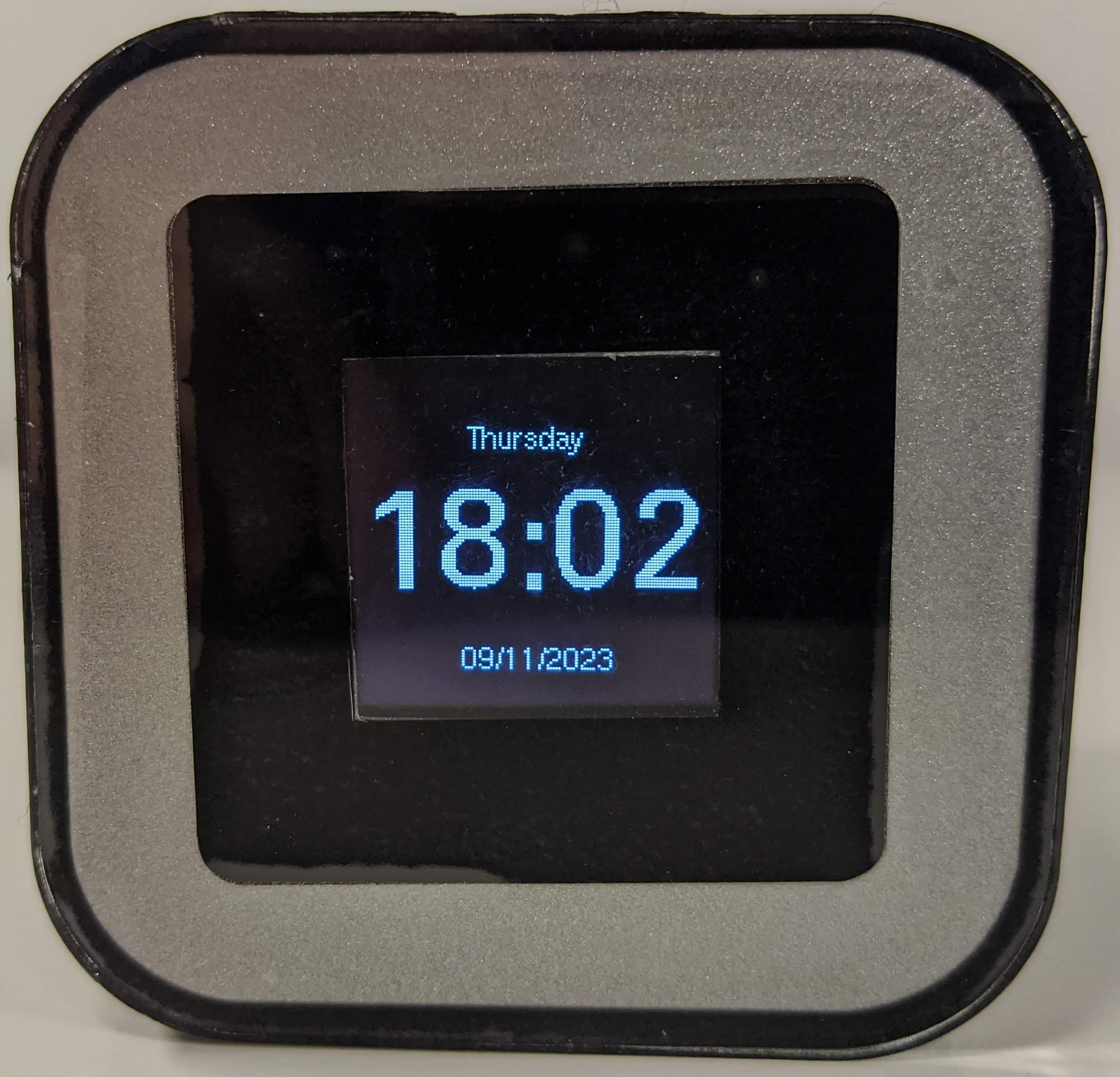
This is the third version of the "Sunrise Alarm Clock" project. The first version used an Arduino Mega and an LCD keypad shield. The second version used a Wemos D1 mini (ESP8266) and 0.96" OLED on a single custom PCB. This design was fully functional but it did not look like an alarm clock. I started version 3 with the aim of making the alarm look more premium.

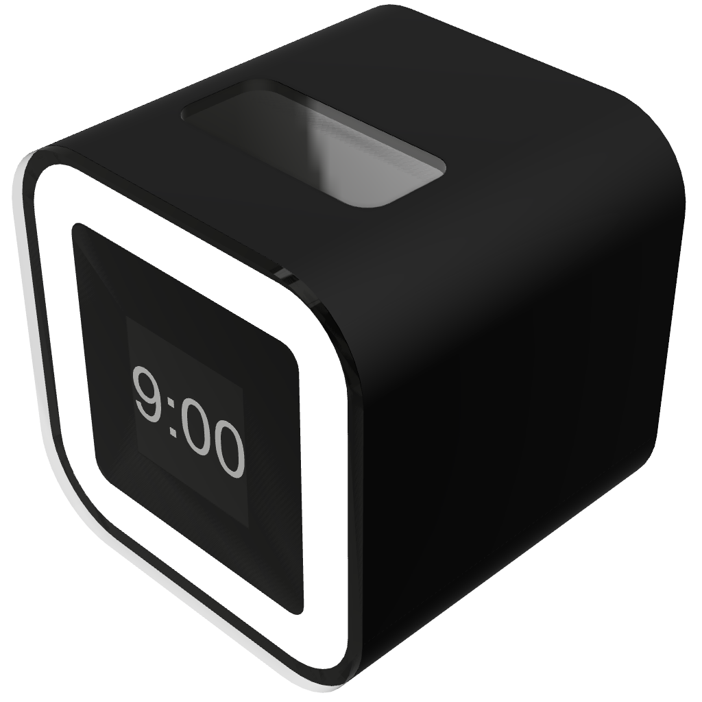
Alarm V1 Alarm V2 Alarm V3 Concept

Alarm V1, Alarm V2 and Alarm V3 Concept

This project was sponsored by PCBWay. To order high-quality, custom PCBs go to PCBWay.com

Brief

The alarm needed to:

  • Tell the time
  • Use a real-time clock (RTC) to keep the time
  • Use an NTP server to update the time periodically
  • Include a larger, 1.5" OLED
  • Include three capacitive touch buttons
  • Include two timed USB ports
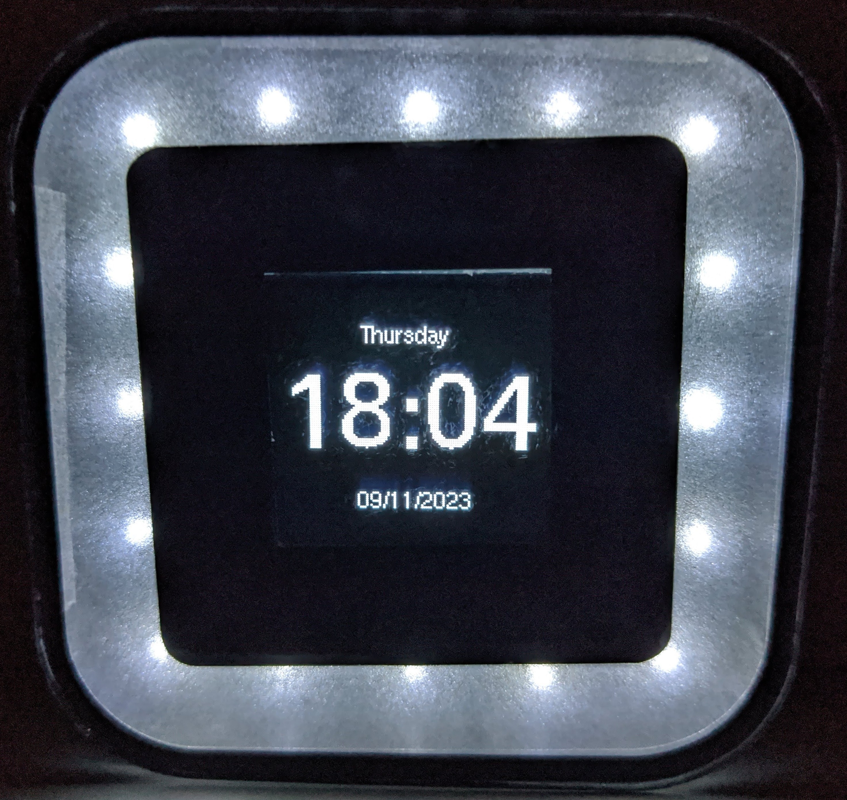
  • Include a bright ringlight on the clock face
  • Include a buzzer
  • Have a premium feel

Development Roadmap

The following roadmap outlines the planned milestones for the project. Each step includes testing and documenting.

VersionDescription
V3.1-alphaCapture Schematic
V3.2-alphaDesign Main PCB
V3.3-alphaDesign Light PCB
V3.4-alphaDesign Button PCB
V3.5-alphaDesign and Fabricate Enclosure
V3.6-alphaSolder and Assemble
V3.7-alphaTest Hardware and Document
V3.8-alphaProgram Inputs and Outputs
V3.9-alphaImplement App Infrastructure
V3.10-alphaDevelop Alarm App
V3.11-alphaDevelop Light App
V3.12-alphaDevelop USB App
V3.13-alphaDevelop Settings App
V3.14-alphaImplement WiFi, NTP Time Sync and Settings Portal
V3.0-releaseInitial Release (Document, Test and Fix Bugs)

Circuitry

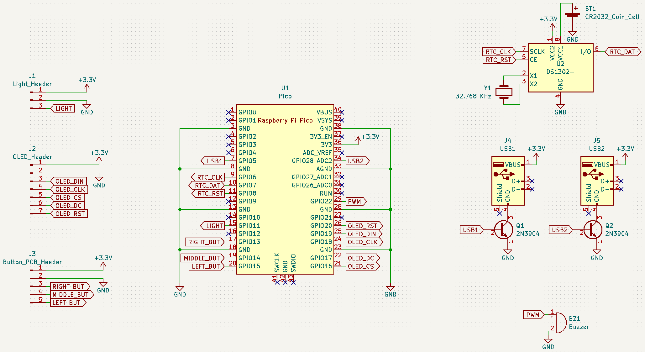
Schematics

Main PCB

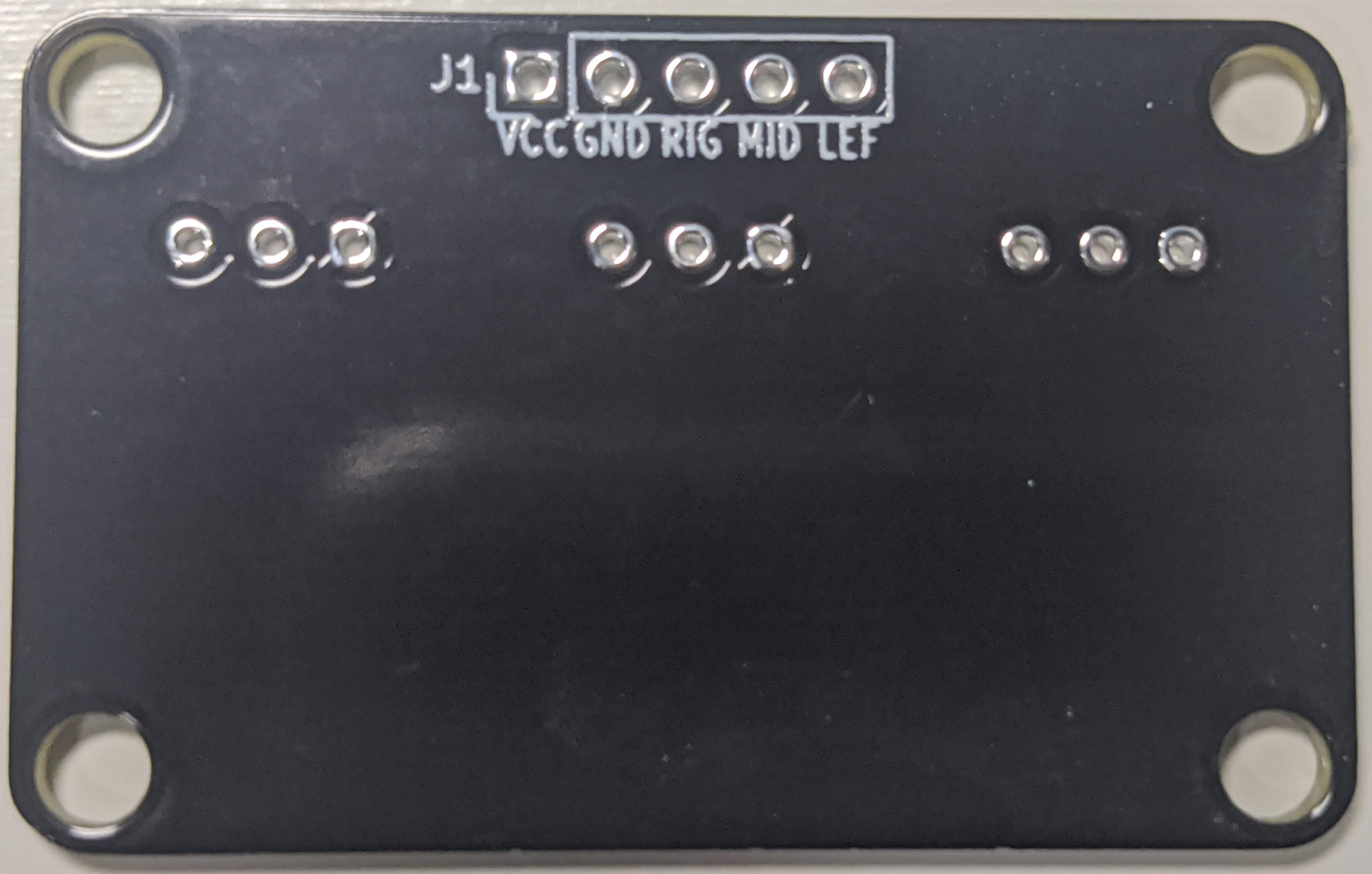
Button PCB
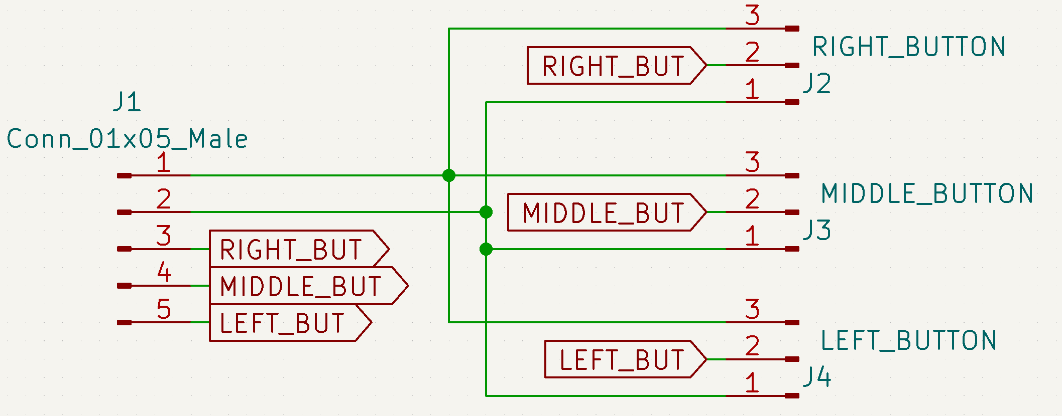
Light PCB
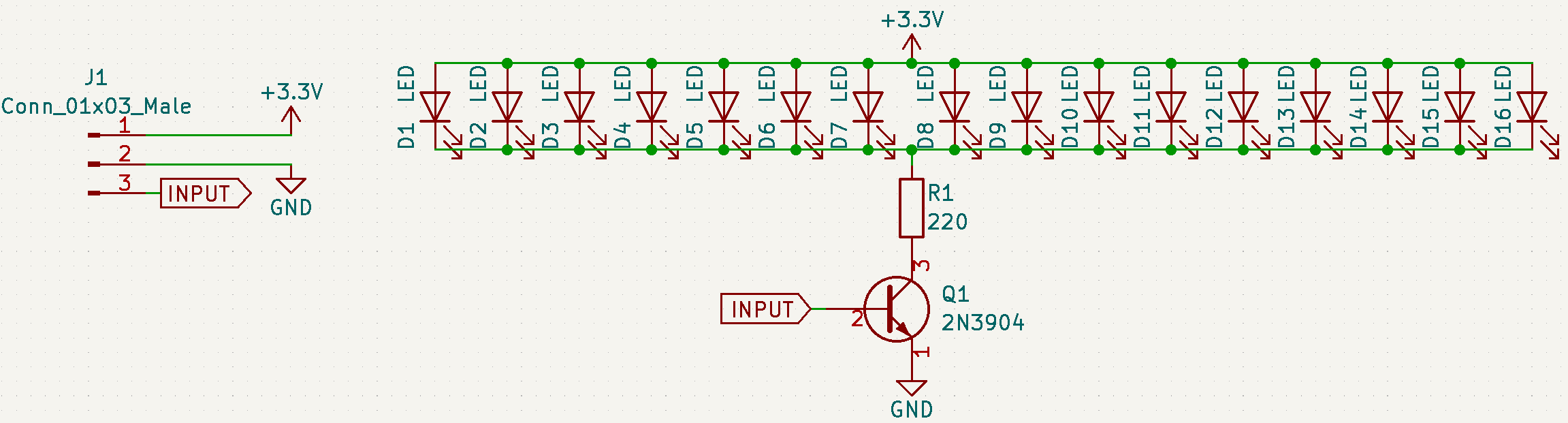
PCB Design

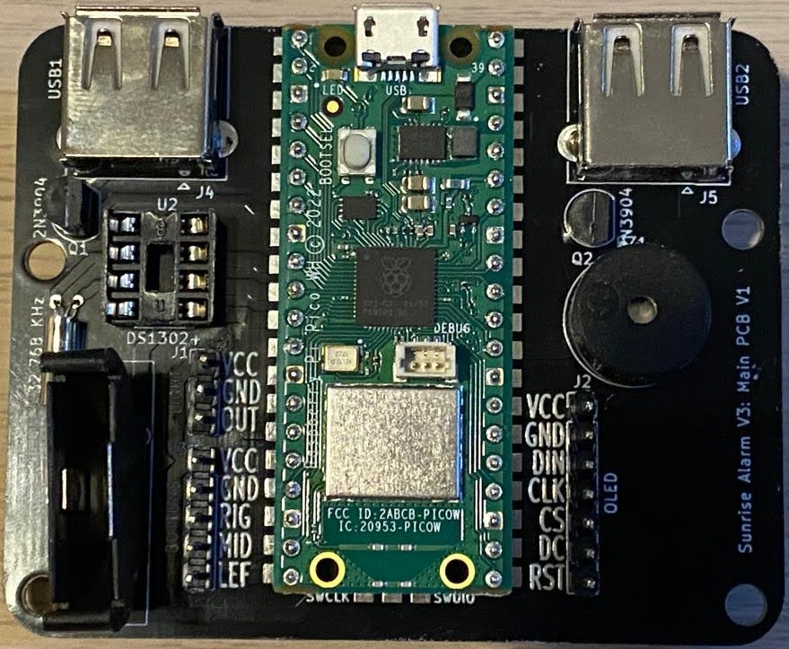
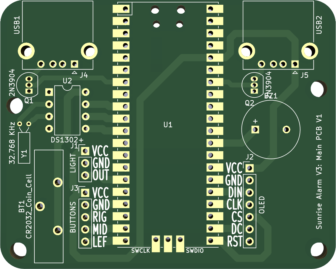
Main PCB
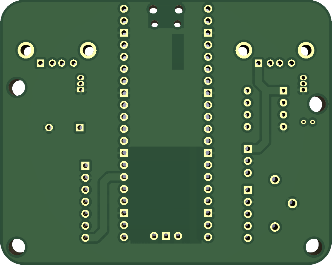
Main PCB Front Main PCB Back

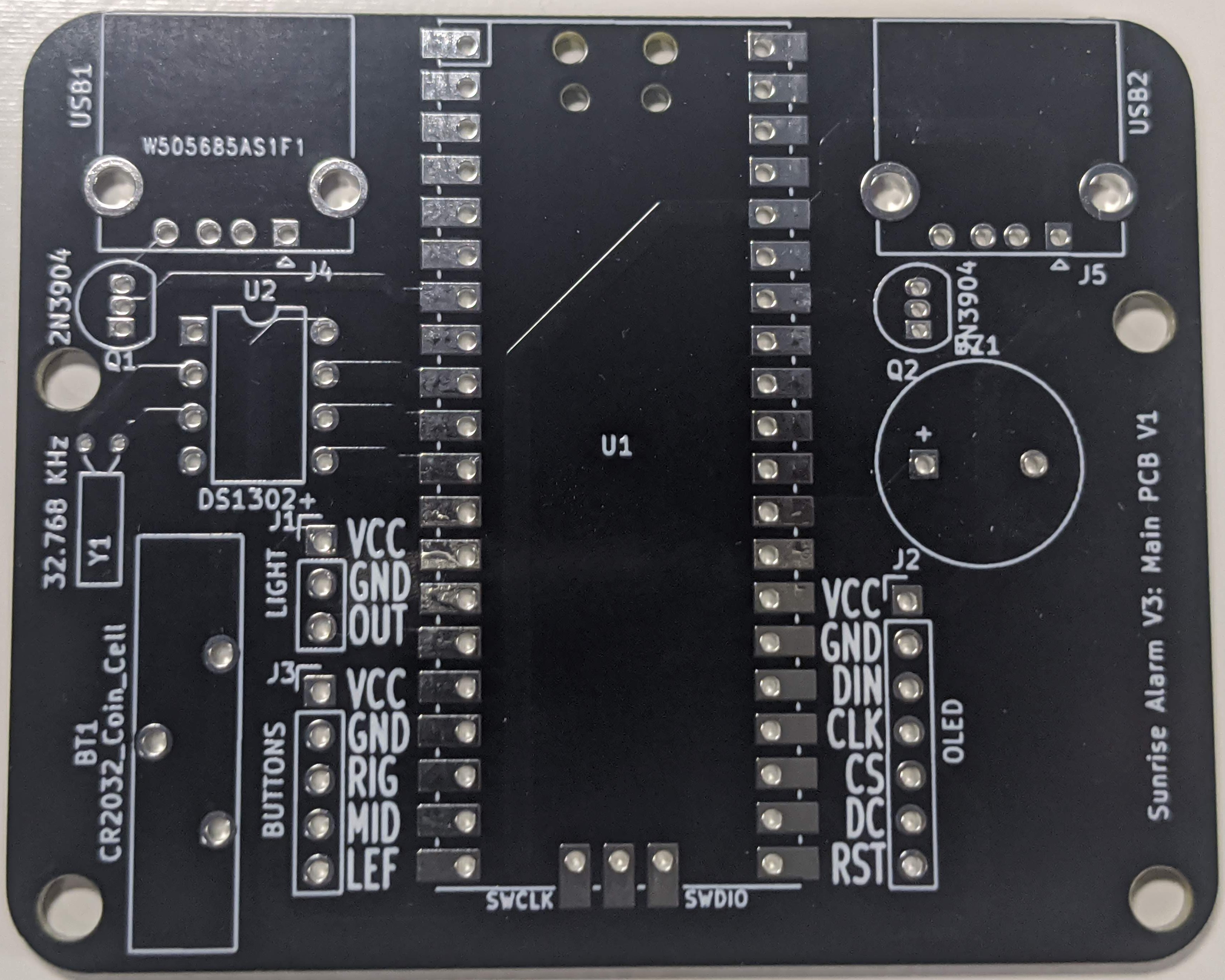
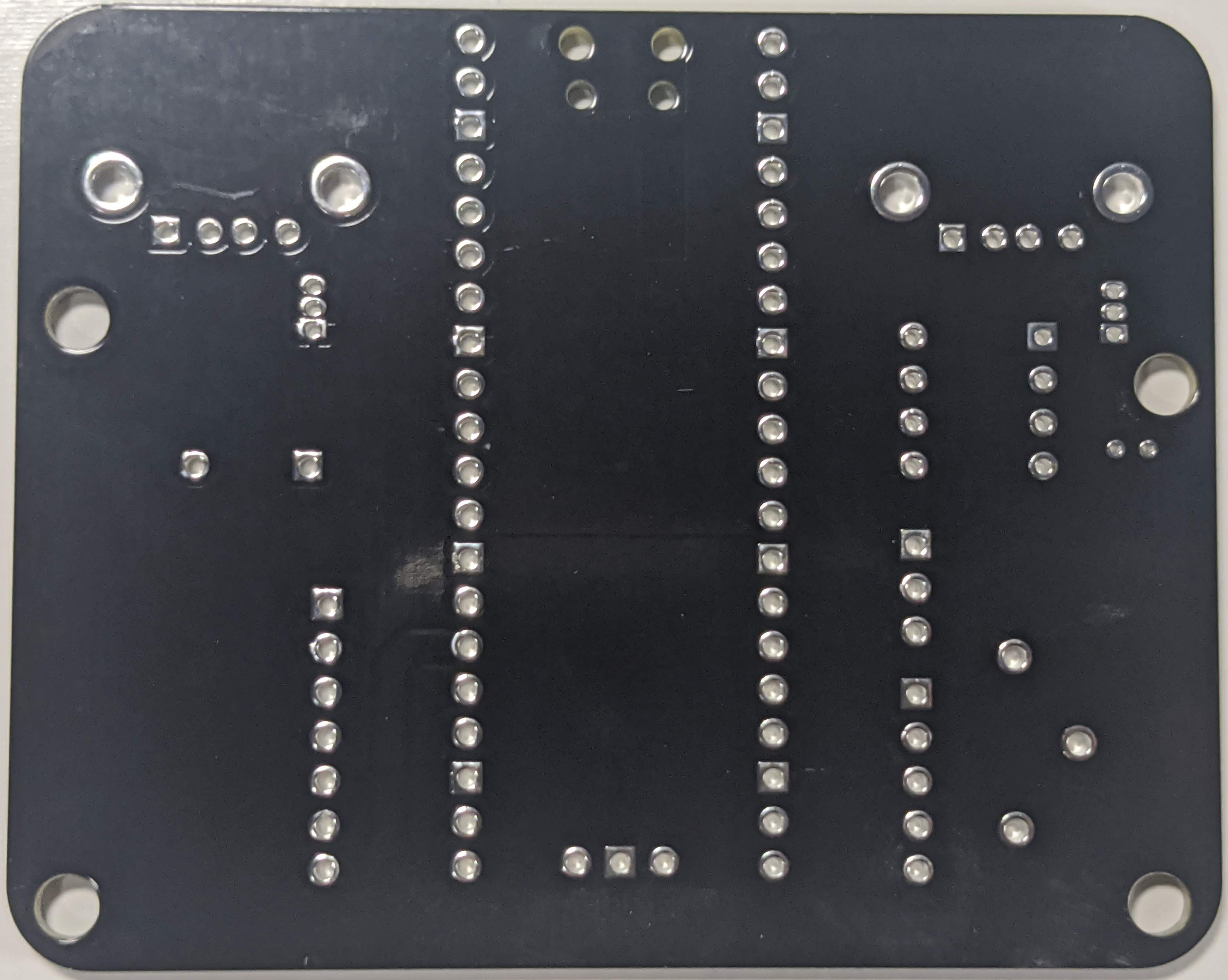
Main PCB Front and Back

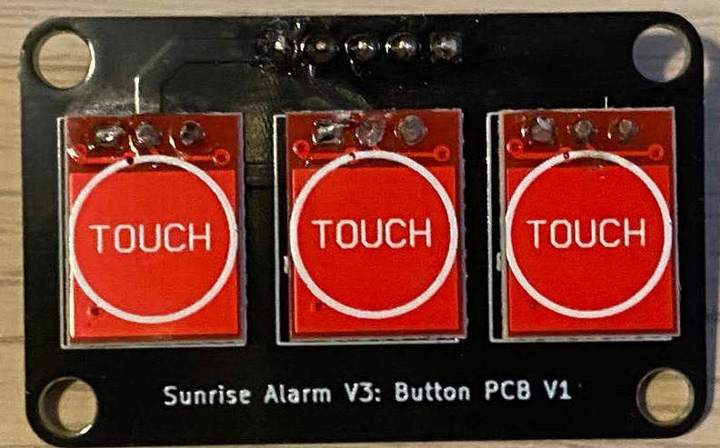
Button PCB
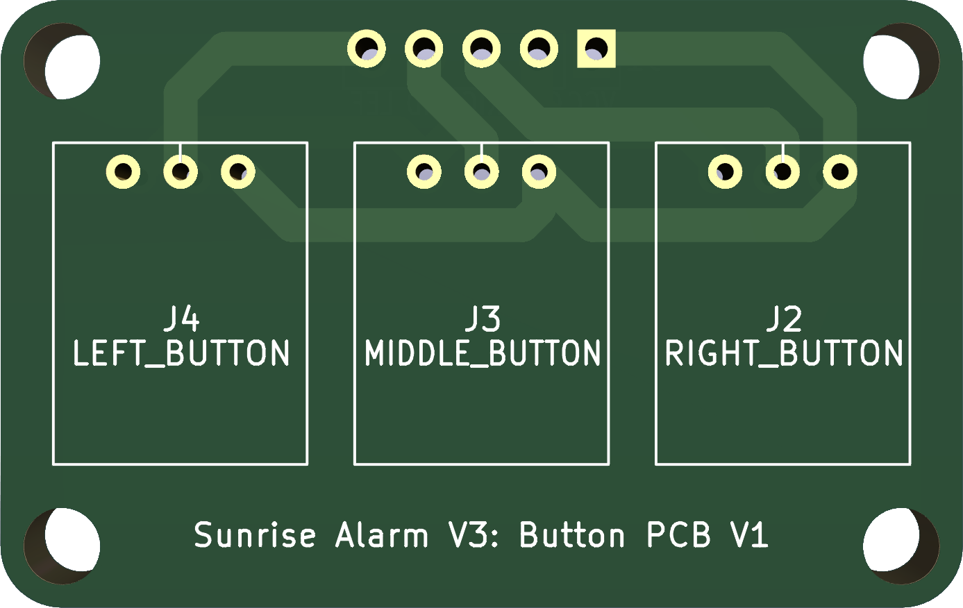
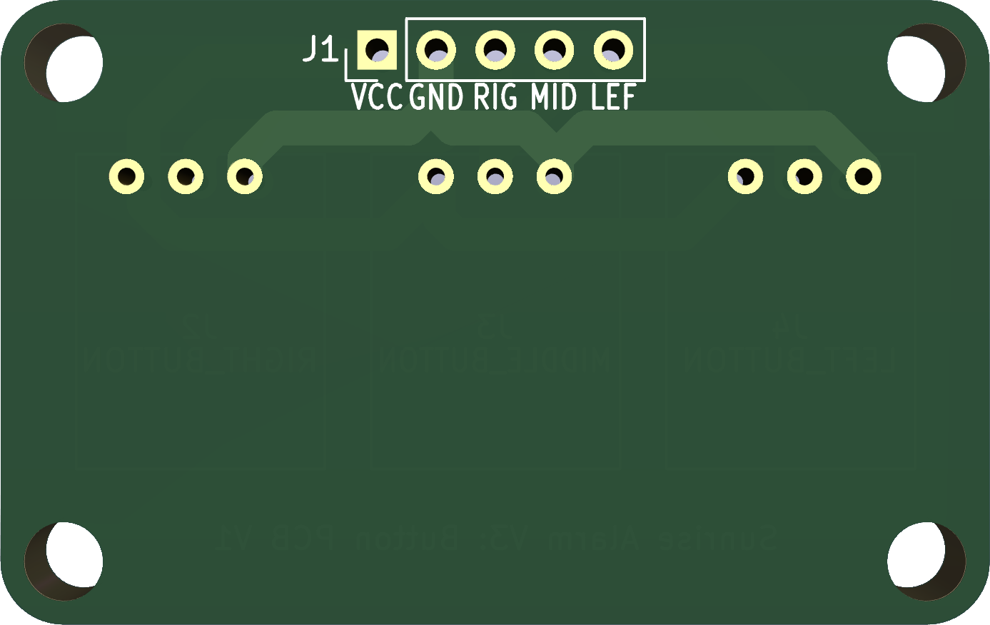
Main PCB Front Main PCB Back

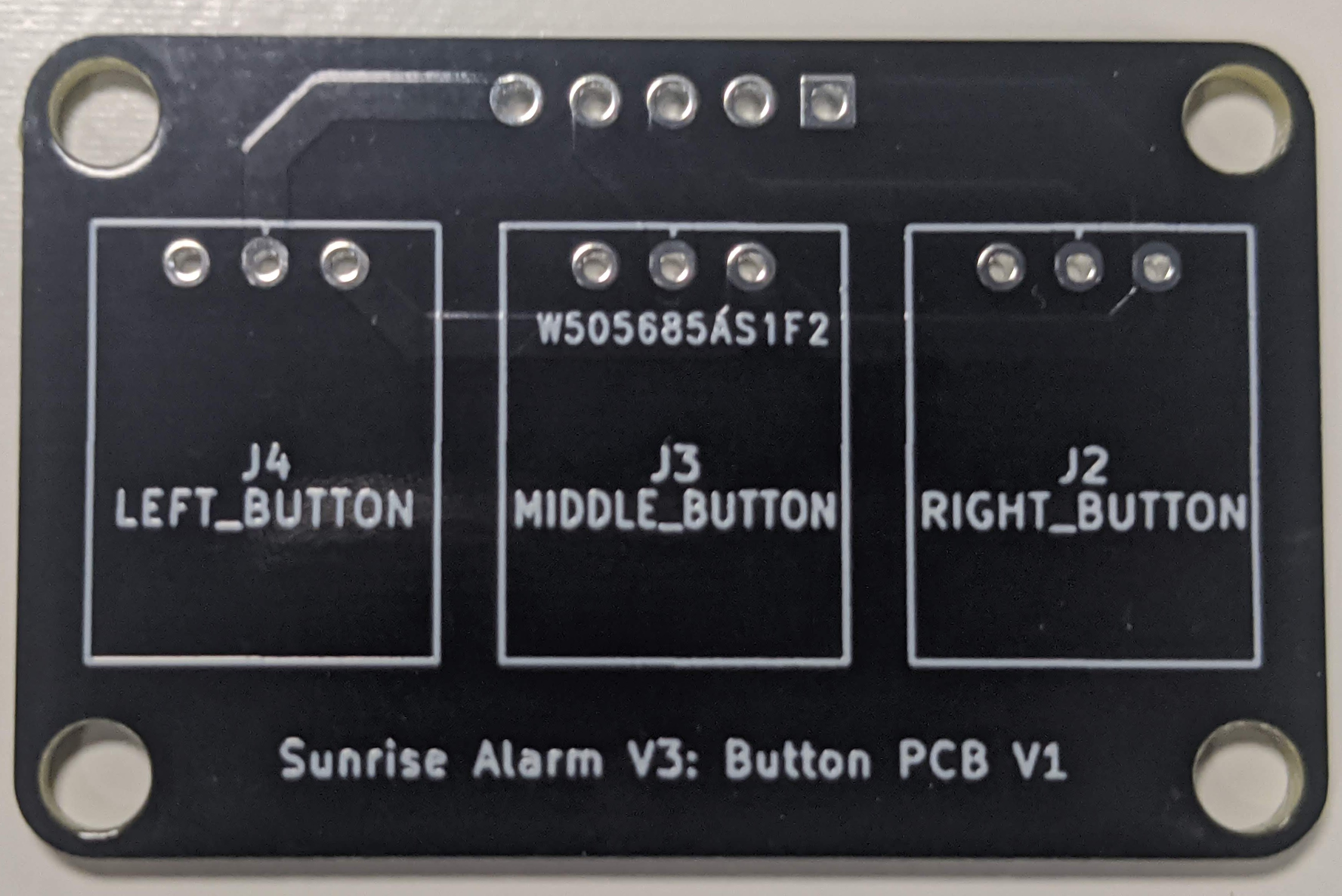
Button PCB Front and Back

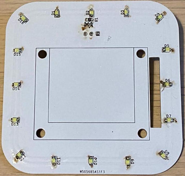
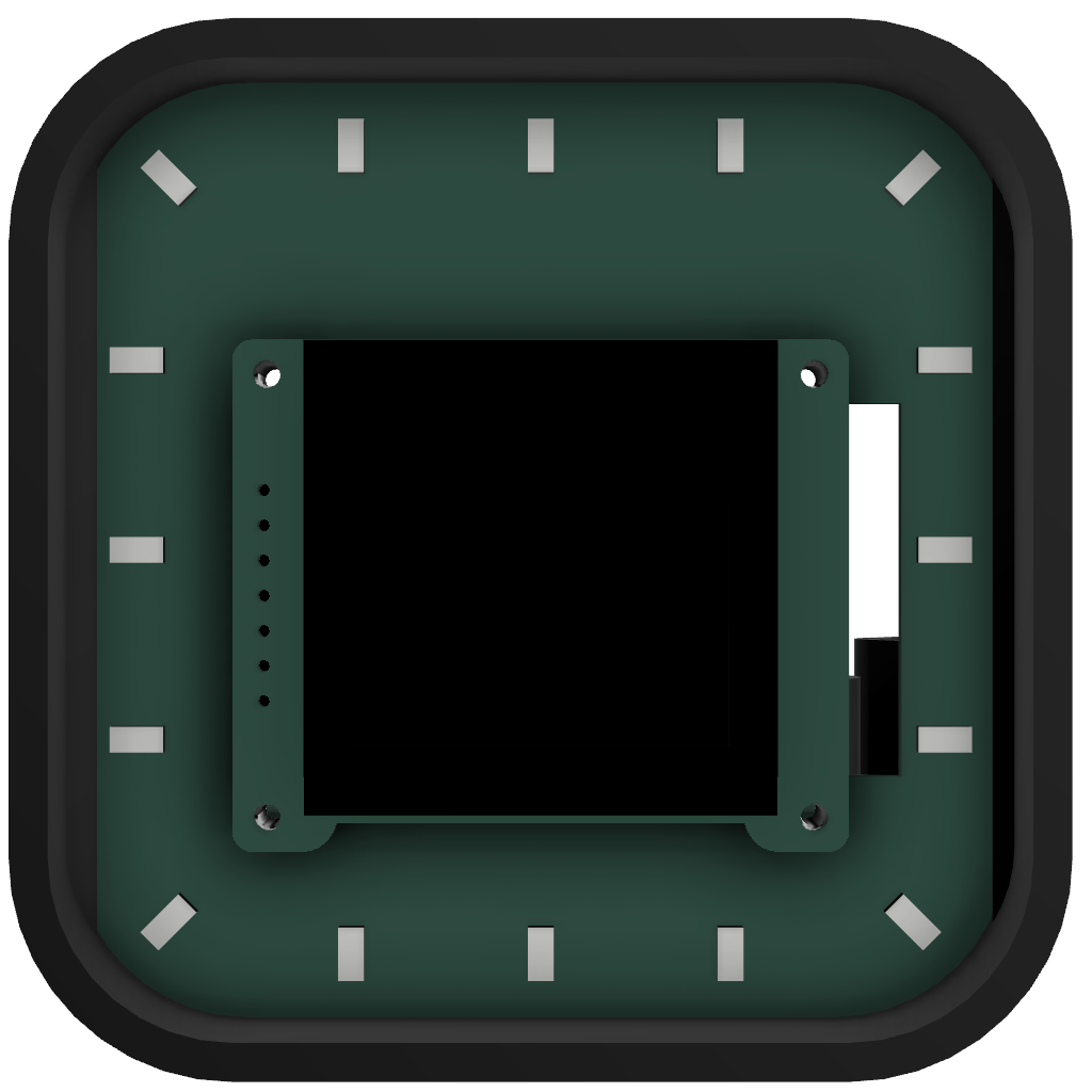
Light PCB
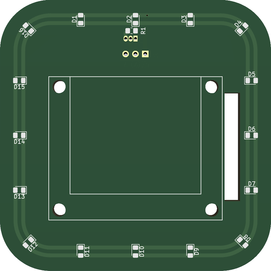
Main PCB Front Main PCB Back

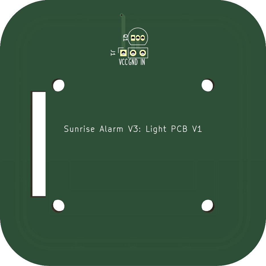
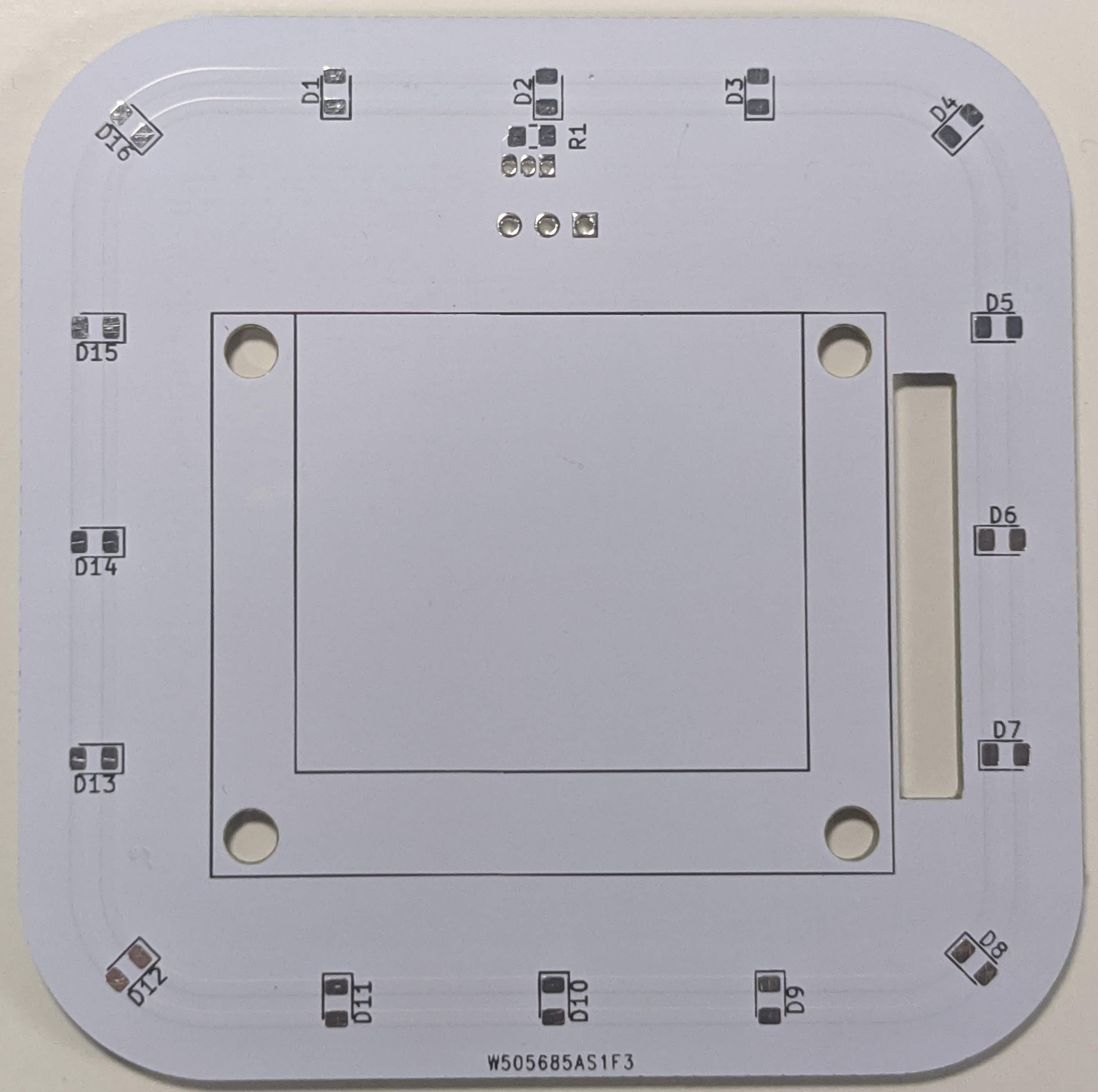
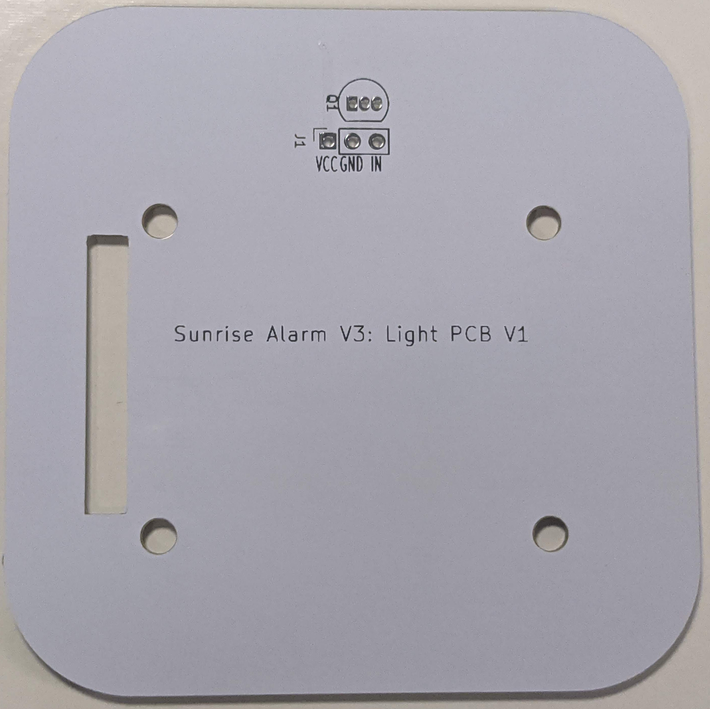
Light PCB Front and Back

Soldering

I was really impressed by the quality of the PCBs sent by PCBWay. To order high-quality, custom PCBs go to PCBWay.com.

Main PCB
Main PCB Front Main PCB Back

Main PCB Front and Back

Main PCB Soldered

Button PCB
Main PCB Front Main PCB Back

Button PCB Front and Back

Button PCB Soldered

Light PCB
Main PCB Front Main PCB Back

Light PCB Front and Back

Light PCB Soldered

Enclosure

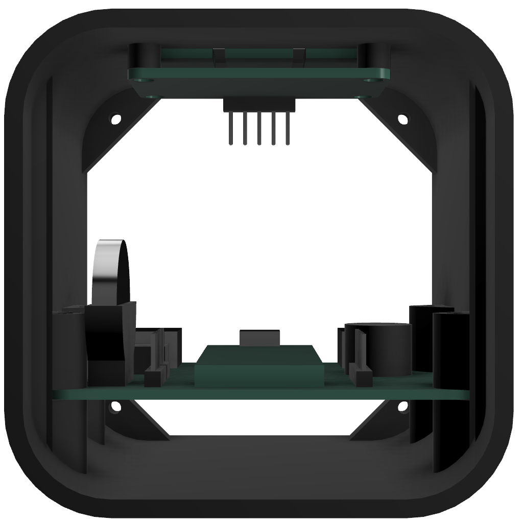
CAD Enclosure

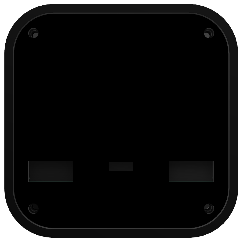
Alarm Enclosure Front Alarm Enclosure Alarm Enclosure Back
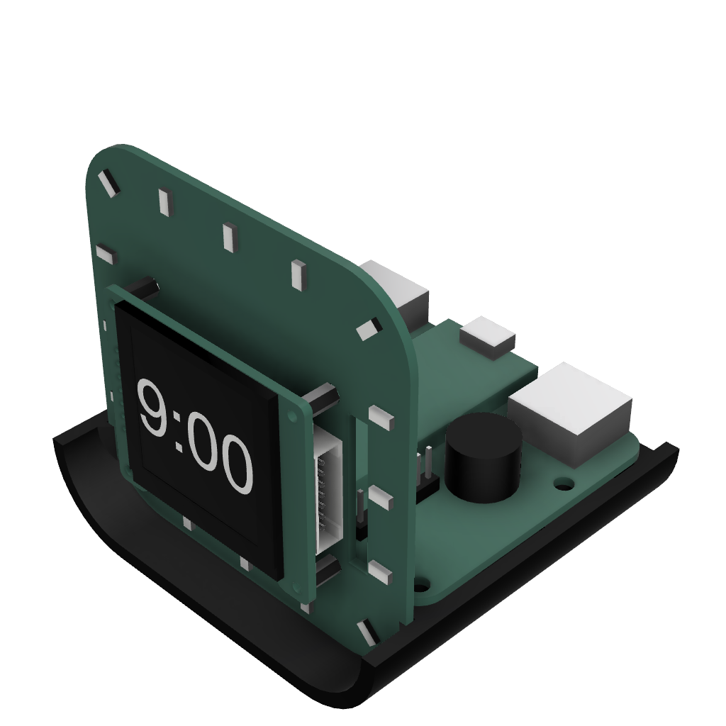
Alarm Enclosure Open Front Alarm Enclosure Open Alarm Enclosure Open Front

Assembled Enclosure

Alarm V1 Alarm V2

Code

Documentation

View the Doxygen documentation for this project here.

How to Add a New App

  1. Copy the TemplateApp.h and TemplateApp.cpp files, changing their names to reflect your app.
  2. Change the header guards, file headers and and include statements to the new file names.
  3. Do a find and replace for the phrase "TemplateApp" replacing it with the name of your app (both files).
  4. Add code to each of the functions.
  5. Include the header file in the main program.
  6. Instantiate the new ____App object.
  7. Increment the noOfApps variable.
  8. Add a reference to the new app object at the next index of the apps array. e.g.apps[i] = &____App;.

Further Work

In future I would like to;

  • Change the design to not use vinyl as it is difficult to get a perfect result using it.
  • Add software functions:
    • Wake up games
    • Daily weather forecast
    • Daily calendar events
    • Log sleep and wake times
    • Mood tracker
    • Habit tracker
Parts

19
QtyValueFootprintReferences
16LEDLED_SMD:LED_0805_2012Metric_Pad1.15x1.40mm_HandSolderD1, D2, D3, D4, D5, D6, D7, D8, D9, D10, D11, D12, D13, D14, D15, D16
1220Resistor_SMD:R_0805_2012Metric_Pad1.20x1.40mm_HandSolderR1
12N3904Package_TO_SOT_THT:TO-92_InlineQ1
1Conn_01x03_MaleConnector_PinSocket_2.54mm:PinSocket_1x03_P2.54mm_VerticalJ1

More from SeanP2001/Sunrise_Alarm_Clock_V3

2
  • 2 layers70 × 56 mmMain PCB, the printed circuit board in 3D

    Main PCB

    SeanP2001/Sunrise_Alarm_Clock_V3

    This is the third version of the "Sunrise Alarm Clock" project. The first version used an Arduino Mega and an LCD keypad shield. The second version used a Wemos D1 mini (ESP8266) and 0.96" OLED on a single custom PCB.

    12 parts1GPL-3.0
  • 2 layers42.5 × 26.8 mmButton PCB, the printed circuit board in 3D

    Button PCB

    SeanP2001/Sunrise_Alarm_Clock_V3

    This is the third version of the "Sunrise Alarm Clock" project. The first version used an Arduino Mega and an LCD keypad shield. The second version used a Wemos D1 mini (ESP8266) and 0.96" OLED on a single custom PCB.

    4 parts1GPL-3.0

Similar boards

  • 2 layers43.9 × 27.7 mmTcd1304-4v, the printed circuit board in 3D

    Tcd1304-4v

    OpnTec/open-spectrometer-hardware

    Open source VIS spectrometer

    19 parts1.5k
  • 2 layers50 × 60 mmDebate Device, the printed circuit board in 3D

    Debate Device

    hackclub/OnBoard

    💡 Join 1,000 teenagers and make your first PCB with a $100 grant!

    19 parts915
  • 2 layers102.9 × 96.7 mmISA adapter, the printed circuit board in 3D

    ISA adapter

    polpo/picogus

    Emulation of ISA sound cards and CD-ROM on Raspberry Pi Pico (GUS, SB/Adlib, MPU-401, Tandy, CMS, Panasonic CD-ROM) with USB mouse/joystick support

    19 parts805
  • 2 layers60 × 39 mmPs2usb, the printed circuit board in 3D

    Ps2usb

    rasteri/HIDman

    Adapting USB devices to work on old computers

    19 parts432
  • 2 layers70.1 × 43.2 mmIaq device, the printed circuit board in 3D

    Iaq device

    nkitanov/iaq_board

    IAQ Board is a DIY (Do-It-Yourself) device for measuring internal air quality

    19 parts396
  • 2 layers80 × 80 mmGB BRK CPU G1, the printed circuit board in 3D

    GB BRK CPU G1

    Gekkio/gb-hardware

    Game Boy -related custom hardware by gekkio

    19 parts379CC-BY-4.0
  • 2 layers25.4 × 25.4 mmIna169, the printed circuit board in 3D

    Ina169

    Ardumower/ardumower

    Develop an open source robotic lawn mower (HW+SW reference platform)

    19 parts282
  • 2 layers58.4 × 28.6 mmNew rele, the printed circuit board in 3D

    New rele

    zmaker/arduino_cookbook

    gli sketch del nuovo progetto Arduino Cookbook e dei video di YouTube

    19 parts269

Questions

How big is the Light PCB PCB?

It measures 70 × 70 mm and has 2 copper layers, 1.6 mm thick.

What parts does the Light PCB use?

19 parts. The full list of its parts is on this page, with links to each part's symbol and footprint where PCBKit's library has them.

Where can I download the Light PCB KiCad files?

From the SeanP2001/Sunrise_Alarm_Clock_V3 repository on GitHub, at the commit this page was made from: the board is PCBs/Light_PCB/Light_PCB.kicad_pcb and its schematic PCBs/Button_PCB/Button_PCB.kicad_sch. PCBKit opens the board in the browser, with nothing to install.

Can I use the Light PCB design in my own project?

Its repository publishes it under the GPL-3.0 licence: you may reuse it on that licence's terms (keep the author's notice, and for a copyleft licence share your changes alike).