2 layers65 × 56 mm
 Sealo21/RPi_3dprinter_control_sys
Lighting, temperature, and sensor contoller for a 3d printing enclosure using a Raspberry Pi and touch screen device
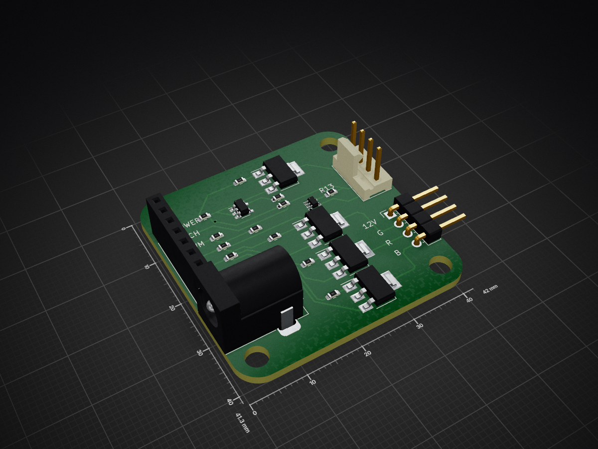
LED FAN CONTROLLER is an open-source printed circuit board by Sealo21, from the Sealo21/RPi_3dprinter_control_sys repository on GitHub. It is a 2-layer board of 42 × 41.3 mm with 23 parts on 22 nets, routed with 124 tracks and 10 vias.
It is built around the MC74HC1G04DFT2, MIC5231-3.3YM5-TR and IRLL014TRPBF. Its parts include 13 resistors, 4 transistors, 4 connectors and 2 ICs.


Environment controller for a 3D printing enclosure using a Raspberry Pi.
Uses a temperature/VOC sensor and a custom PCB controller for the fans and strip LEDs controlled by a Raspberry Pi.
This project is a work-in-progress. It is functional...but still a beta.
Install the latest version of Raspian OS on your Raspberry Pi
Edit your configuration to enable 'I2C' and 'Remote GPIO' under the interfaces tab
Save and restart your RPi
Update packages to the latest version:
sudo apt updateA GPIO Extender will be needed to have the screen and GPIO be plugged in at the same time.
There are a few options for the hardware of your controller
A cheap option is to breadboard the design using the design schematics from the file 'LED_FAN_CONTROLLER.kicad_sch'
You may need to download and install Kicad to view this schematic.
Here are the design requirements to breadboard this project:

The other option is to use the PCB schematics and manufacture the PCB.
I have not done this yet as I am working on an upgrade to the current version.
Your experience may change based on which touchscreen is used.
Use xinput-calibrator to calibrate the touch screen.
sudo apt-get install xinput-calibratorYou will find this program under Menu -> Preferences -> Calibrate Touchscreen.
Follow the instuctions given in the command line to save the calibration.
If the system does not recognize the touchscreen, check with the manufacturer for driver files.
The sensors I recieved do not have a standard coloring scheme.
I have made a table below to list where the pins must go and their color.


| Pin (On Sensor) | Name | Description | Color | Pin Placement (On RPi) |
|---|---|---|---|---|
| 1 | VCC | Supply Voltage | Green | Pin 2 (5V) |
| 2 | GND | Ground | Blue | Pin 6 (GND) |
| 3 | SDA | I2C: Data | Yellow | Pin 3 (SDA) |
| 4 | SCL | I2C: Clock | Black | Pin 5 (SCL) |
| 5 | SEL | Interface Select | Red | Pin 9 (GND) |
| 6 | NC | Do Not Connect | Brown | NC |
If the device is not recognized by the system, connect the VCC to 3.3V pin and then back to 5V.
The device can function on both 3.3V and 5V but 5V is recommended by the manufacturer.
Use the i2cdetect command to check connected I2C devices.
i2cdetect -y 1You should see a device listed with a number value.
More information about this installation can be found here
| Qty | Value | Footprint | References |
|---|---|---|---|
| 6 | 10000 | Resistor_SMD:R_0603_1608Metric | R3, R4, R5, R8, R12, R13 |
| 5 | 1000 | Resistor_SMD:R_0603_1608Metric | R1, R2, R9, R10, R11 |
| 4 | IRLL014TRPBF | Package_TO_SOT_SMD:SOT-223-3_TabPin2 | Q2, Q3, Q4, Q5 |
| 1 | 1700 | Resistor_SMD:R_0603_1608Metric | R6 |
| 1 | 3300 | Resistor_SMD:R_0603_1608Metric | R7 |
| 1 | Barrel_Jack | Connector_BarrelJack:BarrelJack_Horizontal | J2 |
| 1 | Conn_01x04 | Connector:FanPinHeader_1x04_P2.54mm_Vertical | J4 |
| 1 | Conn_01x04 | Connector_PinHeader_2.54mm:PinHeader_1x04_P2.54mm_Horizontal | J3 |
| 1 | Conn_01x07_MountingPin | Connector_PinSocket_2.54mm:PinSocket_1x07_P2.54mm_Vertical | J5 |
| 1 | MC74HC1G04DFT2 | Package_TO_SOT_SMD:SOT-353_SC-70-5 | U2 |
| 1 | MIC5231-3.3YM5-TR | Package_TO_SOT_SMD:SOT-23-5 | U1 |

google/mozc-devices
Circuit diagrams and firmware source code for Gboard DIY keyboards


Duet3D/Duet-2-Hardware
The KiCAD source for the Duet 3d printer controller see www.duet3d.com
It measures 42 × 41.3 mm and has 2 copper layers, 1.67 mm thick.
23 parts, built around the MC74HC1G04DFT2, MIC5231-3.3YM5-TR and IRLL014TRPBF. The full list of its parts is on this page, with links to each part's symbol and footprint where PCBKit's library has them.
From the Sealo21/RPi_3dprinter_control_sys repository on GitHub, at the commit this page was made from: the board is LED_FAN_CONTROLLER/LED_FAN_CONTROLLER.kicad_pcb and its schematic LED_FAN_CONTROLLER/Aisler rules/aisler-2-layer-simpel.kicad_sch. PCBKit opens the board in the browser, with nothing to install.
Its repository states no licence, so its author keeps all rights: ask Sealo21 before reusing the design.