
2 layers20 × 20 mm

Hybrid coupler boards for circular polarization
Qcn3Rf is an open-source printed circuit board by SatcomRadio, from the SatcomRadio/Hybrid_Couplers repository on GitHub, published under the MIT licence. It is a 2-layer board of 28.5 × 20 mm with 6 parts on 5 nets, routed with 21 tracks and 42 vias.
Its parts include 3 connectors, 2 resistors and 1 IC.
This repo consists of different boards that use different devices to get circular polarized antennas.
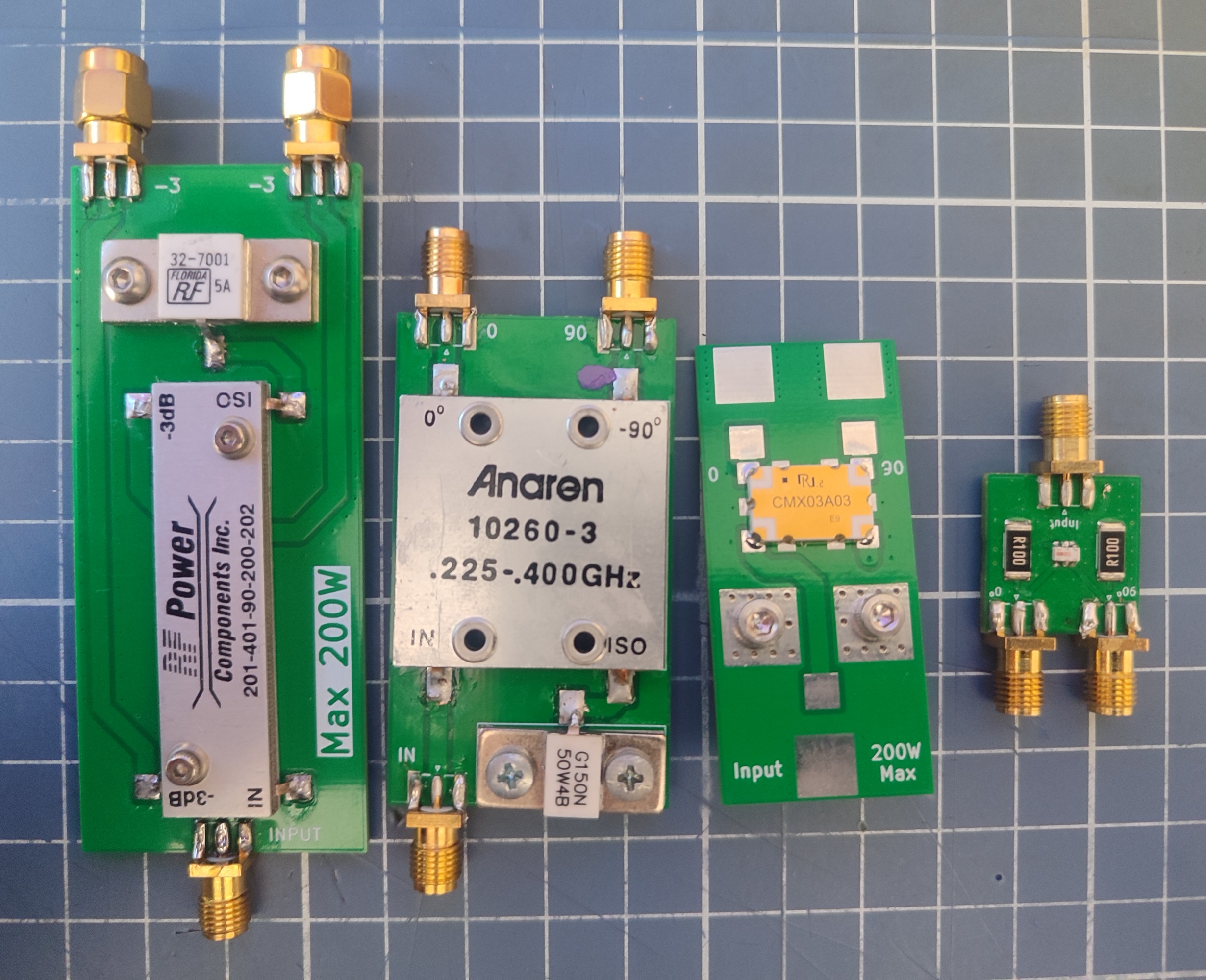
All the PCB boards have a version that where you can use SMA connectors or soldered wires.
If you want to use the SMA connector boards, you will need to buy:
3x SMA connectors for PCB with 1.6mm spacing (aliexpress.com/item/10000000835065.html)Important!
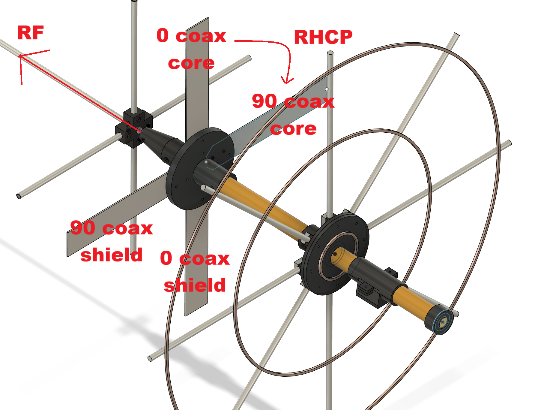
You must connect them correctly! Each port has to be a "dipole".
Depending on their orientation you will get RHCP or LHCP.
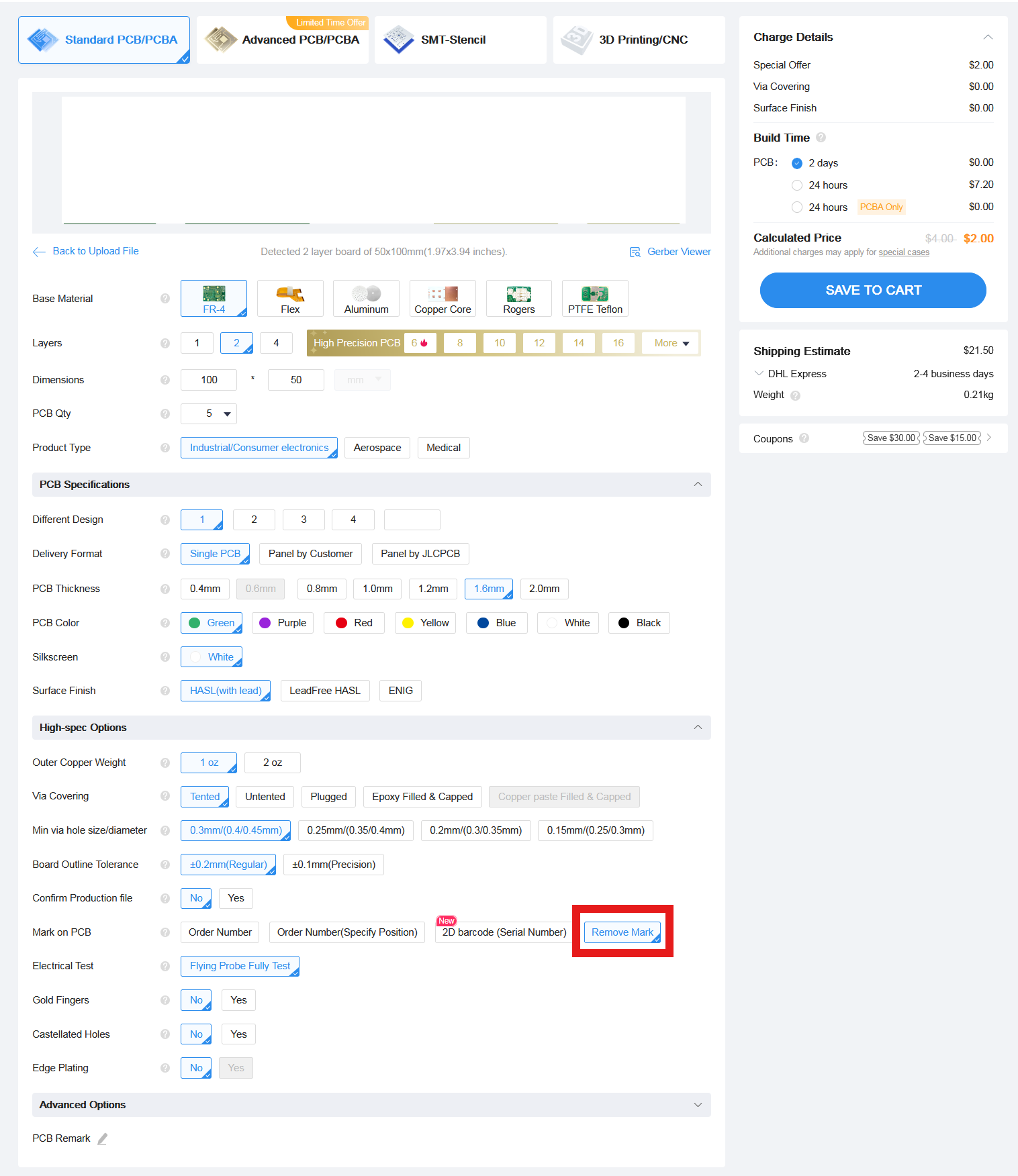
Download the Gerber file you want from this repo and order it a jlcpcb with the default options.
The only option I've changed is to remove the manufacture code mark
Most compact option for high power. Can handle 200W
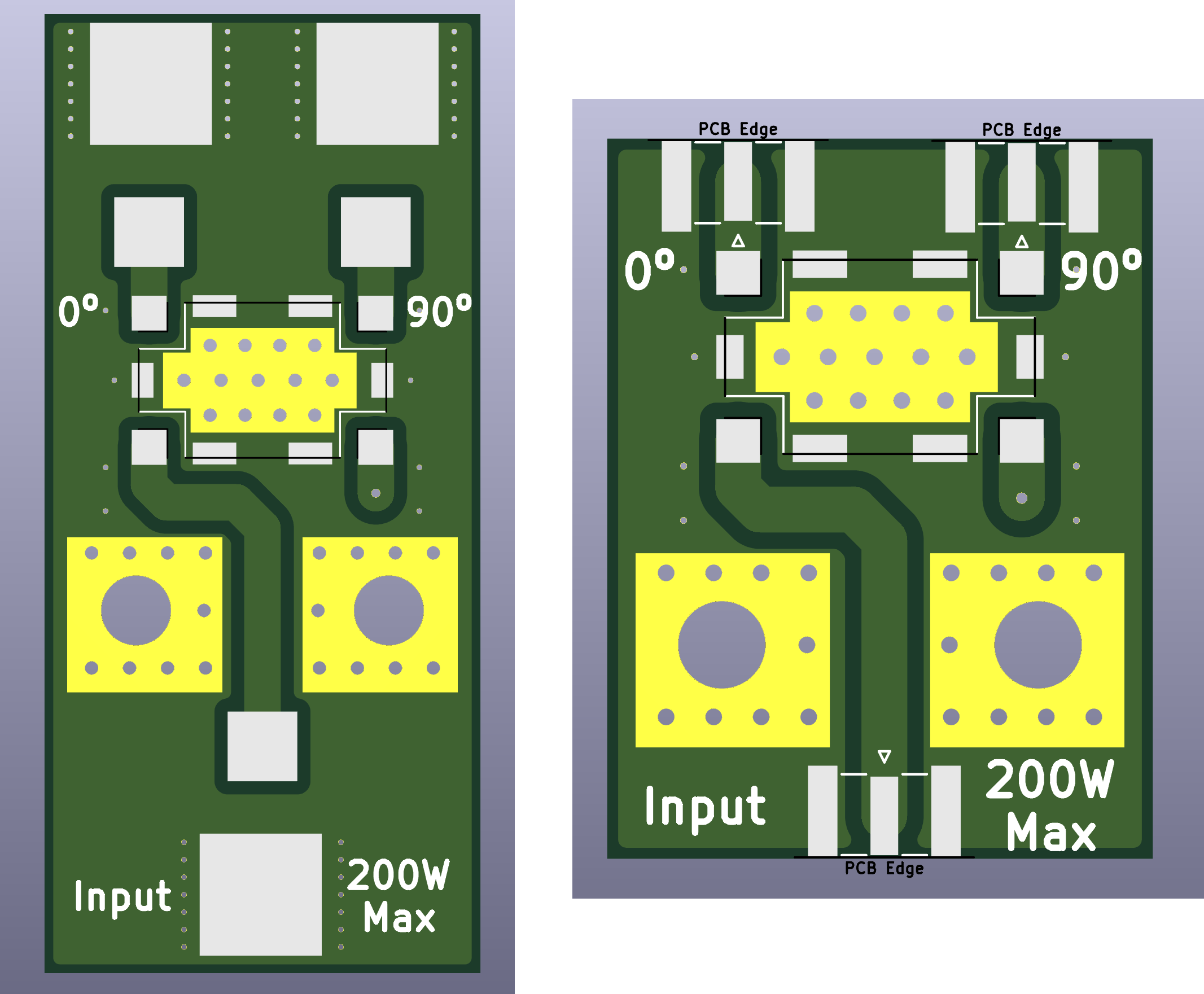
1x CMX03A03 (aliexpress.com/item/1005008506296292.html)
1x G150N 50 ohm RF load (aliexpress.com/item/32909755238.html)Can handle 200W.
Probably an old model made by "Florida RF Labs"
There's no information about this coupler but it's usually sold with a 50 ohm resistance for free.
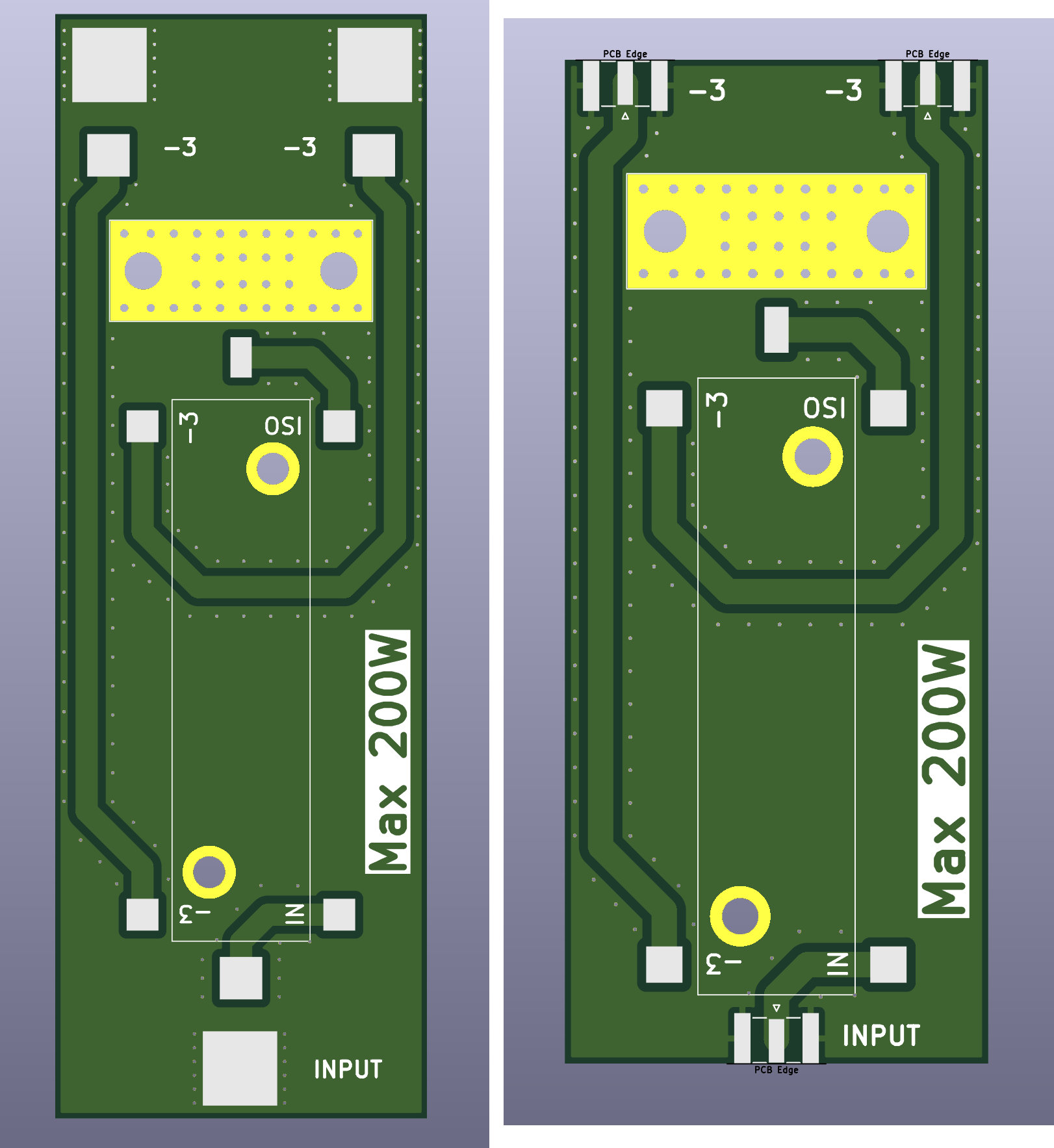
1x RF Power coupler (aliexpress.com/item/32886665884.html)

This resistance is often given for free when you buy the coupler:
1x RF 32-7001 50 ohm RF load (aliexpress.com/i/1005006266356008.html)Can handle 250W.
Outdated so it's difficult to find. Usually it's sold on ebay.
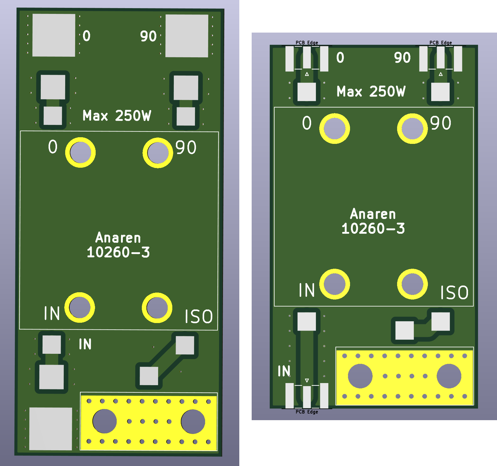
1x Anaren 10260-3
1x G150N 50 ohm RF load (aliexpress.com/item/32909755238.html)Most compact option. Can handle 15W.
To be used only with handheld radios.
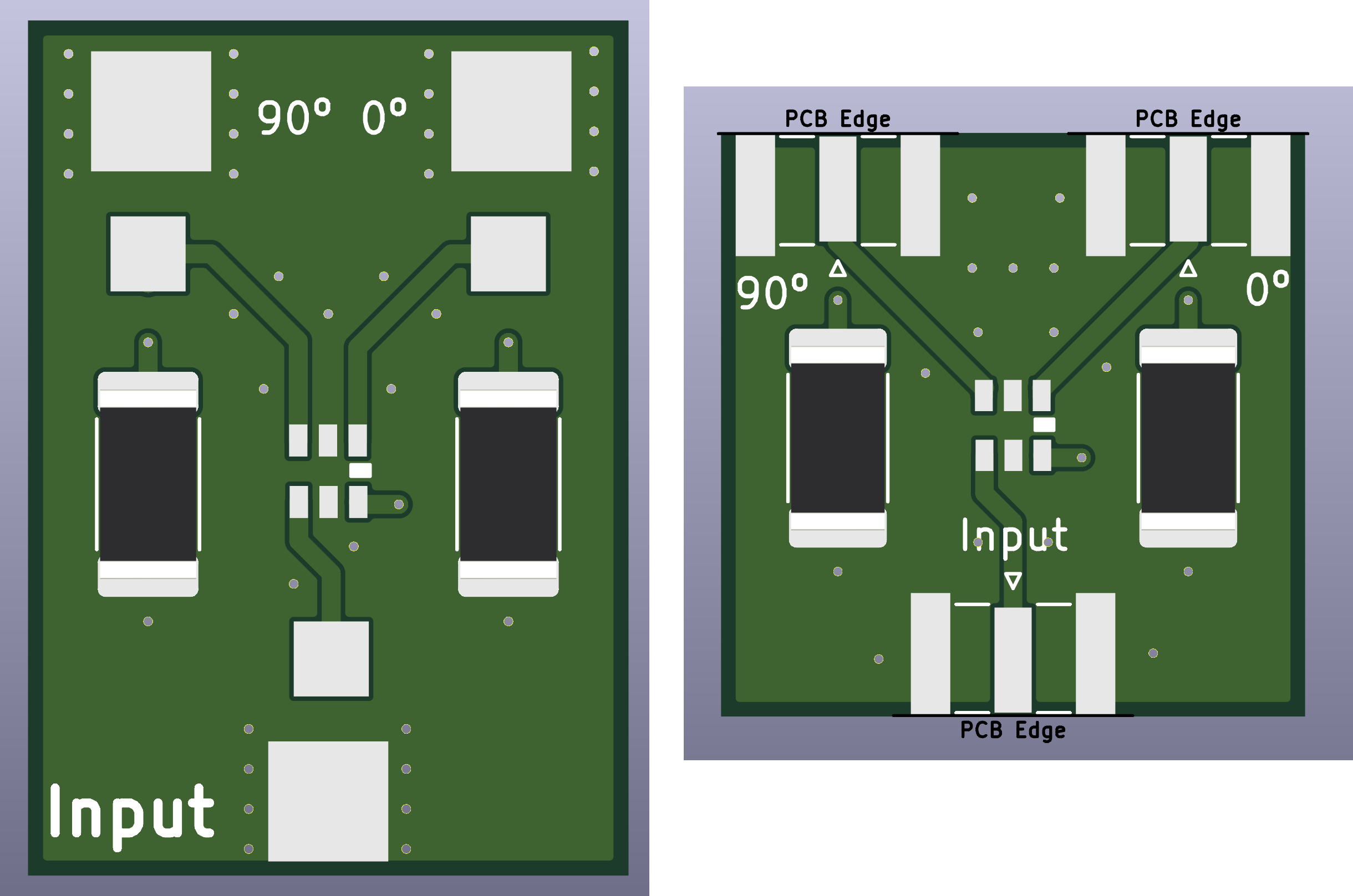
1x QCN-3 (aliexpress.com/item/1005002788551103.html)
2x SMD resistor 2512 100Ω 2W resistor (https://es.aliexpress.com/item/1005007255020731.html)| Qty | Value | Footprint | References |
|---|---|---|---|
| 3 | Conn_Coaxial_Small | Footprints:Wire connector_S | J0, J90, Ji1 |
| 2 | 100 | Resistor_SMD:R_2512_6332Metric_Pad1.40x3.35mm_HandSolder | R1, R2 |
| 1 | QCN3 | Footprints:QCN3 | U1 |


byrantech/laptop
anyon_e, a highly integrated, high end, open source laptop. Attempt the impossible.


Jcparkyn/dpoint
Open-source digital stylus using camera tracking and inertial measurements

VoronDesign/Voron-Hardware
Cool Hardware designed by the Voron Design group

hoglet67/RGBtoHDMI
Bare-metal Raspberry Pi project that provides pixel-perfect sampling of Retro Computer RGB/YUV video and conversion to HDMI

hackclub/OnBoard
💡 Join 1,000 teenagers and make your first PCB with a $100 grant!

Luos-io/luos_engine
Open-source and real-time orchestrator for cyber-physical-systems, to easily design, test and deploy embedded applications and digital twins.

It measures 28.5 × 20 mm and has 2 copper layers, 1.6 mm thick.
6 parts. The full list of its parts is on this page, with links to each part's symbol and footprint where PCBKit's library has them.
From the SatcomRadio/Hybrid_Couplers repository on GitHub, at the commit this page was made from: the board is Kicad/QCN3/QCN3_RF/Qcn3Rf.kicad_pcb and its schematic Kicad/Anaren/Anaren_RF/AnarenRf.kicad_sch. PCBKit opens the board in the browser, with nothing to install.
Its repository publishes it under the MIT licence: you may reuse it on that licence's terms (keep the author's notice, and for a copyleft licence share your changes alike).