Skip to the content
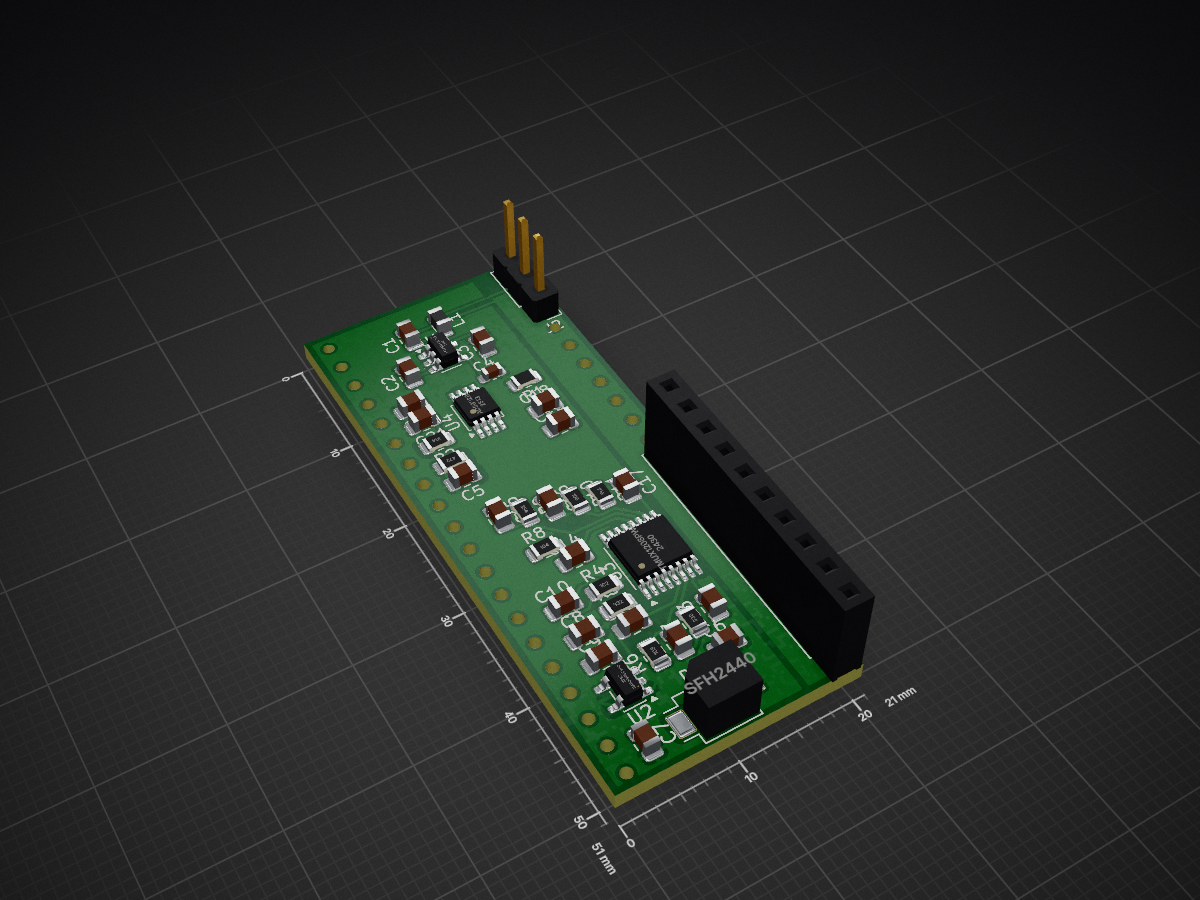
2 layers21 × 51 mmPD detector pro, the printed circuit board in 3D

PD detector pro

Samuel20040521/flico

flico 是一台以 Raspberry Pi Pico 為核心、用來量測螢幕 / 光源閃爍(flicker)的小型自製 儀器。光訊號由 Vishay BPW34 矽 PIN 光二極體接收,經 Microchip MCP6004 跨阻 放大器(TIA)轉成電壓,由 Pico 的 ADC 取樣後,透過 USB-CDC 串列傳回桌面端的 Rust GUI(eframe + egui)即時繪出時域波形與 FFT 頻譜。

Size
21 × 51 mm
Copper layers
2
Thickness
1.6 mm
Parts
41
Nets
24
Pads
146
Tracks, vias
147, 4
Pours
4
Routed
Yes
KiCad
KiCad 10.0 (file 20260206)
Created
8 Jun 2026
Updated
23 Oct 2026

Overview

PD detector pro is an open-source printed circuit board by Samuel20040521, from the Samuel20040521/flico repository on GitHub. It is a 2-layer board of 21 × 51 mm with 41 parts on 24 nets, routed with 147 tracks and 4 vias.

It is built around the LP5907MFX-3.3 and SFH 2440. Its parts include 21 capacitors, 11 resistors, 4 ICs, 2 connectors and 1 diode.

Main components

2

README

README.md

flico

flico = flicker + pico。

flico 是一台以 Raspberry Pi Pico 為核心、用來量測螢幕 / 光源閃爍(flicker)的小型自製 儀器。光訊號由 Vishay BPW34 矽 PIN 光二極體接收,經 Microchip MCP6004 跨阻 放大器(TIA)轉成電壓,由 Pico 的 ADC 取樣後,透過 USB-CDC 串列傳回桌面端的 Rust GUI(eframe + egui)即時繪出時域波形與 FFT 頻譜。

這個 repo 是專案的線性故事版本:每個 commit 大致對應一天的開發事件, 對應的研究日誌(report/research-log/)用敘事體把當天的決策、失敗、學到的東西 寫下來。雜亂的真實開發狀態收在另一個 repo(SOC_Final/)。

想做到什麼

把「看不見的閃」變成「看得見的曲線」。常見場景:

  • 螢幕 PWM 調光的可見化:筆電 / 手機 / 顯示器低亮度下的 ~200 Hz–25 kHz PWM 閃爍, 用肉眼看不到,但會讓人疲勞、頭痛。
  • 日光燈 / LED 燈具的 100 Hz / 120 Hz 漣波:確認照明品質。
  • 遮蔽測試:用手指、紙片在 BPW34 前面晃動,即時看 ADC 訊號擺動,驗證整條訊號鏈。

最終目標是一台可以單獨開機、自己看波形 + FFT 的 handheld 儀器(目前 host GUI 跑在筆電上;3D 列印外殼還在進行中,見 report/research-log/log.pdf 結尾的「展望」)。

資料夾結構

資料夾角色主要技術棧
firmware/燒在 Pico 內的韌體Pico SDK C++、MicroPython(雙路線並存)
host/桌面端 GUI,跟 Pico 通訊Rust(eframe + egui + egui_plot),serialport
hardware/三版 PCB 設計史KiCad 8 + SKiDL(中間版)+ JLCPCB
mechanical/3D 列印外殼(進行中)Fusion 360 Python API
simulation/PySpice TIA 模擬與量測對照Python(uv)、PySpice、ngspice
report/research-log/每日研究日誌 + Gemini 對話原檔XeLaTeX(xeCJK + TW-Kai)、biblatex+biber

firmware/ 內部

子資料夾內容
cpp-version/主要韌體:Pico SDK C++,含 SSD1306 OLED 驅動 + ADC + USB-CDC 串流(5/12 從 MicroPython fork 過來)
python-version/MicroPython 版主程式(歷史路線,5/8 ~ 5/11 用)
led-light-test-cpp-version/C++ blink,Pico SDK 工具鏈試水溫
led-light-test-python-version/MicroPython blink,VS Code 環境驗證(5/8)

hardware/ 內部(三版線性史)

子資料夾內容狀態
first-version/pico_flicker_shield —— 5/8 KiCad GUI workflow 起手,schematic 完成放棄,留作設計史
second-version/PD_detector_pro —— 5/18 用 SKiDL 程式化重寫 + pcbnew API 自動 layout放棄,但 flipped analog island 的領悟帶到 final
final-version/SOC_Final —— 5/20~5/25 投產版,5/25 21:23 送 JLCPCB已送 PCBA

final-version/ 內有 Gerber/(14 個製造檔)、SOC_Final_JLCPCB.zip(36 KB 一鍵上傳包)、 TIA_Gain_100M.wbk(KiCad spice 工作簿)、tools/jlcpcb_bom_cpl.py(BOM/CPL 生成腳本)。

如何在本地跑通過程

各子資料夾互不耦合,看你想做什麼進對應資料夾即可。

1. 桌面 GUI(host/)

sh
cd host
cargo run --release                # 接實體 Pico,從 USB-CDC 拉資料
cargo run --release -- --synth     # 用合成正弦+雜訊跑 demo(不用接 Pico)
  • macOS 會自動掃 /dev/cu.usbmodem*;Windows 預設 COM3(已知 Pico 第一次插的位置)。

  • 也可以 build 成 WASM,丟瀏覽器跑:

    sh
    cargo build --release --target wasm32-unknown-unknown
  • 跨平台 release binary(macOS universal + Windows x86_64)透過 GitHub Actions .github/workflows/release-rust_flico.yml 在 push tag 時自動 cross-compile。

2. 韌體(firmware/cpp-version/)

sh
cd firmware/cpp-version
mkdir -p build && cd build
cmake .. && make -j$(nproc)
# 產出 pico_flicker.uf2,把 Pico 用 BOOTSEL 鍵插上拖進 RPI-RP2 磁碟即可

需要 Pico SDK 並設好 PICO_SDK_PATH 環境變數。

想用 MicroPython 路線跑舊版的話,在 VS Code 裝 MicroPython 擴充, 把 firmware/python-version/{main.py,ssd1306.py} 上傳到 Pico 即可。

3. PySpice 模擬(simulation/)

sh
cd simulation
uv sync                              # 安裝 Python 相依
uv run python main.py                # DC sweep → figures/tia_sweep.png
uv run python ac_transient_sweep.py  # AC Bode + 20 kHz PWM transient

需要先有 libngspice0(Linux,apt install libngspice0-dev)或 ngspice(macOS:brew install ngspice)。詳見 simulation/report.md。

把實測噪音餵 spice 的 pipeline:

sh
cd host
uv run python convert.py             # flicker_*.csv → kicad_noise_pwl.txt
# 把 kicad_noise_pwl.txt 路徑塞進 final-version/TIA_Gain_100M.wbk 的 PWL source

4. PCB(hardware/final-version/)

用 KiCad 8.0 打開 SOC_Final.kicad_pro。

  • 看 ERC 結果:ERC.rpt

  • 看完整投產包:SOC_Final_JLCPCB.zip

  • 重新生 BOM/CPL:

    sh
    cd hardware/final-version
    python tools/jlcpcb_bom_cpl.py

KiCad project stem 刻意保留為 SOC_Final(repo 名雖然是 flico,但 KiCad internal cross-references 跟 stem 綁死,改 stem blast radius 太大)。

5. 3D 列印外殼(mechanical/,進行中)

在 Fusion 360 → Scripts and Add-Ins → + → 指到 mechanical/fusion_pico_fixture.py,跑一次就會 parametrically 生出 fixture 模型。 參數(housing 60 × 30 × 20 mm 等)集中在檔頭常數區。

目前還是 fixture 級別的 stub,不是整機 enclosure。升級計畫見研究日誌結尾的 「展望」section。

6. 研究日誌(report/research-log/)

sh
cd report/research-log
xelatex log.tex && biber log && xelatex log.tex && xelatex log.tex
open log.pdf

需要 TW-Kai(全字庫正楷體)字型,可從 CNS11643 下載頁取得。

寫新 entry 的工作流:

  1. 新增 entries/YYYY-MM-DD.tex(每日一檔)

  2. 圖 / 影片放 figures/YYYY-MM-DD/

  3. 原始 Gemini 對話放 gemini_discuss_history/MMDD[-suffix].txt

  4. 在 log.tex 條目區追加:

    latex
    \logentry{YYYY-MM-DD}{當日標題}
    \input{entries/YYYY-MM-DD}
  5. 重新編譯。

設計細節

電路拓樸、R_F / C_F 選擇邏輯、量測 vs 模擬對照,看 simulation/report.md。

PCB 三版的決策史、host 從 Python 改寫到 Rust 的效能對照、JLCPCB 投產的務實妥協, 看研究日誌(report/research-log/log.pdf)。

Parts

41
QtyValueFootprintReferences
5100nFCapacitor_SMD:C_0805_2012MetricC5, C6, C8, C18, C20
410uFCapacitor_SMD:C_0805_2012MetricC7, C9, C19, C21
31uFCapacitor_SMD:C_0805_2012MetricC1, C2, C3
2100kResistor_SMD:R_0805_2012MetricR2, R8
10Resistor_SMD:R_0805_2012MetricR1
1100pFCapacitor_SMD:C_0805_2012MetricC14
110MResistor_SMD:R_0805_2012MetricR11
110kResistor_SMD:R_0805_2012MetricR6
110nFCapacitor_SMD:C_0603_1608MetricC4
110nFCapacitor_SMD:C_0805_2012MetricC10
110pFCapacitor_SMD:C_0805_2012MetricC16
11MResistor_SMD:R_0805_2012MetricR10
11kResistor_SMD:R_0805_2012MetricR4
11nFCapacitor_SMD:C_0805_2012MetricC12
13.3kResistor_SMD:R_0805_2012MetricR5
13.3nFCapacitor_SMD:C_0805_2012MetricC11
1330kResistor_SMD:R_0805_2012MetricR9
1330pFCapacitor_SMD:C_0805_2012MetricC13
133kResistor_SMD:R_0805_2012MetricR7
133pFCapacitor_SMD:C_0805_2012MetricC15
14.7kResistor_SMD:R_0805_2012MetricR3
1600R@100MHzInductor_SMD:L_0805_2012MetricL1
1ADS8326Package_SO:MSOP-8_3x3mm_P0.65mmU4
1Conn_01x03PinHeader_1x03_P2.54mm_VerticalJ2
1Conn_01x10Connector_PinHeader_2.54mm:PinHeader_1x10_P2.54mm_VerticalJ1
1DNPCapacitor_SMD:C_0805_2012MetricC17
1LP5907MFX-3.3Package_TO_SOT_SMD:SOT-23-5U1
1OPA320AIDBVRPackage_TO_SOT_SMD:SOT-23-5U2
1Pico_thruPICO_PINS
1SFH2440OptoDevice:Osram_SFH2440D1
1TMUX1208PWRPackage_SO:TSSOP-16_4.4x5mm_P0.65mmU3

More from Samuel20040521/flico

1
  • 2 layers22.9 × 17.6 mmSOC Final, the printed circuit board in 3D

    SOC Final

    Samuel20040521/flico

    flico 是一台以 Raspberry Pi Pico 為核心、用來量測螢幕 / 光源閃爍(flicker)的小型自製 儀器。光訊號由 Vishay BPW34 矽 PIN 光二極體接收,經 Microchip MCP6004 跨阻 放大器(TIA)轉成電壓,由 Pico 的 ADC 取樣後,透過 USB-CDC 串列傳回桌面端的 Rust GUI(eframe + egui)即時繪出時域波形與 FFT 頻譜。

    23 parts

Similar boards

  • 4 layers160.8 × 12 mmD13, the printed circuit board in 3D

    D13

    git4dcc/RTB_D13

    DCC/RailCom Function Decoder for Minitrix Passenger Cars

    153 partsApache-2.0
  • 4 layers100 × 90 mmSensor dmf board, the printed circuit board in 3D

    Sensor dmf board

    esyywar/Digital-Microfluidic-Control

    A complete digital microfluidic system including PCB hardware, arduino microcontroller firmware and real-time control software.

    58 parts2
  • 4 layers299 × 127 mmLaunch, the printed circuit board in 3D

    Launch

    system76/launch

    System76 Launch Configurable Keyboard

    385 parts1.4kGPL-3.0
  • 2 layers316 × 119 mmTeensy Grovebox, the printed circuit board in 3D

    Teensy Grovebox

    jerry20091103/Teensy_Grovebox

    A portable synth and music multi-tool made with Teensy 4.1

    142 parts150MIT
  • 4 layers96 × 28 mmThelio io, the printed circuit board in 3D

    Thelio io

    system76/thelio-io-hardware

    KiCad electrical design of Thelio Io board

    78 parts70GPL-3.0
  • 2 layers58 × 38.3 mmEsp32-caliper, the printed circuit board in 3D

    Esp32-caliper

    Mew463/esp32-caliper

    It features a built in 150mAh battery and a USB C interface for charging/uploading code.

    44 parts59
  • 4 layers231 × 67 mmBESC G2, the printed circuit board in 3D

    BESC G2

    galpavlin/BESC-G2

    BESC second generation

    300 parts58
  • 4 layers26.4 × 56 mmRPI5-SDexpress Hat, the printed circuit board in 3D

    RPI5-SDexpress Hat

    will127534/RPI5-SDexpress-Hat

    ctrl-c "RPI5-CFE-Hat" ctrl-v "RPI5-SDexpress-Hat"

    51 parts37MIT

Questions

How big is the PD detector pro PCB?

It measures 21 × 51 mm and has 2 copper layers, 1.6 mm thick.

What parts does the PD detector pro use?

41 parts, built around the LP5907MFX-3.3 and SFH 2440. The full list of its parts is on this page, with links to each part's symbol and footprint where PCBKit's library has them.

Where can I download the PD detector pro KiCad files?

From the Samuel20040521/flico repository on GitHub, at the commit this page was made from: the board is hardware/second-version/PD_detector_pro.kicad_pcb and its schematic hardware/final-version/SOC_Final.kicad_sch. PCBKit opens the board in the browser, with nothing to install.

Can I use the PD detector pro design in my own project?

Its repository states no licence, so its author keeps all rights: ask Samuel20040521 before reusing the design.