Skip to the content
2 layers202.4 × 142.2 mmHeart Pendant v2, the printed circuit board in 3D

Large heart PCB LED pendant using Charlieplexing and ATtiny to introduce STEAM concepts or conquer the heart of of loved one!

Size
202.4 × 142.2 mm
Copper layers
2
Thickness
1.6 mm
Parts
32
Nets
15
Pads
79
Tracks, vias
232, 16
Pours
3
Routed
Yes
KiCad
KiCad 5 (file 20171130)
Created
4 Jan 2022
Updated
4 Jan 2022

Overview

Heart Pendant v2 is an open-source printed circuit board by SaltyPaws, from the SaltyPaws/Large-Heart-PCB-LED-Pendant repository on GitHub, published under the MIT licence. It is a 2-layer board of 202.4 × 142.2 mm with 32 parts on 15 nets, routed with 232 tracks and 16 vias.

It is built around the ATTINY25-20SU. Its parts include 20 diodes, 6 resistors, 1 capacitor, 1 IC and 1 connector. It belongs with the AVR (ATmega, ATtiny) boards of this library.

Main components

1

README

README.md

Large LED Heart PCB Pendant

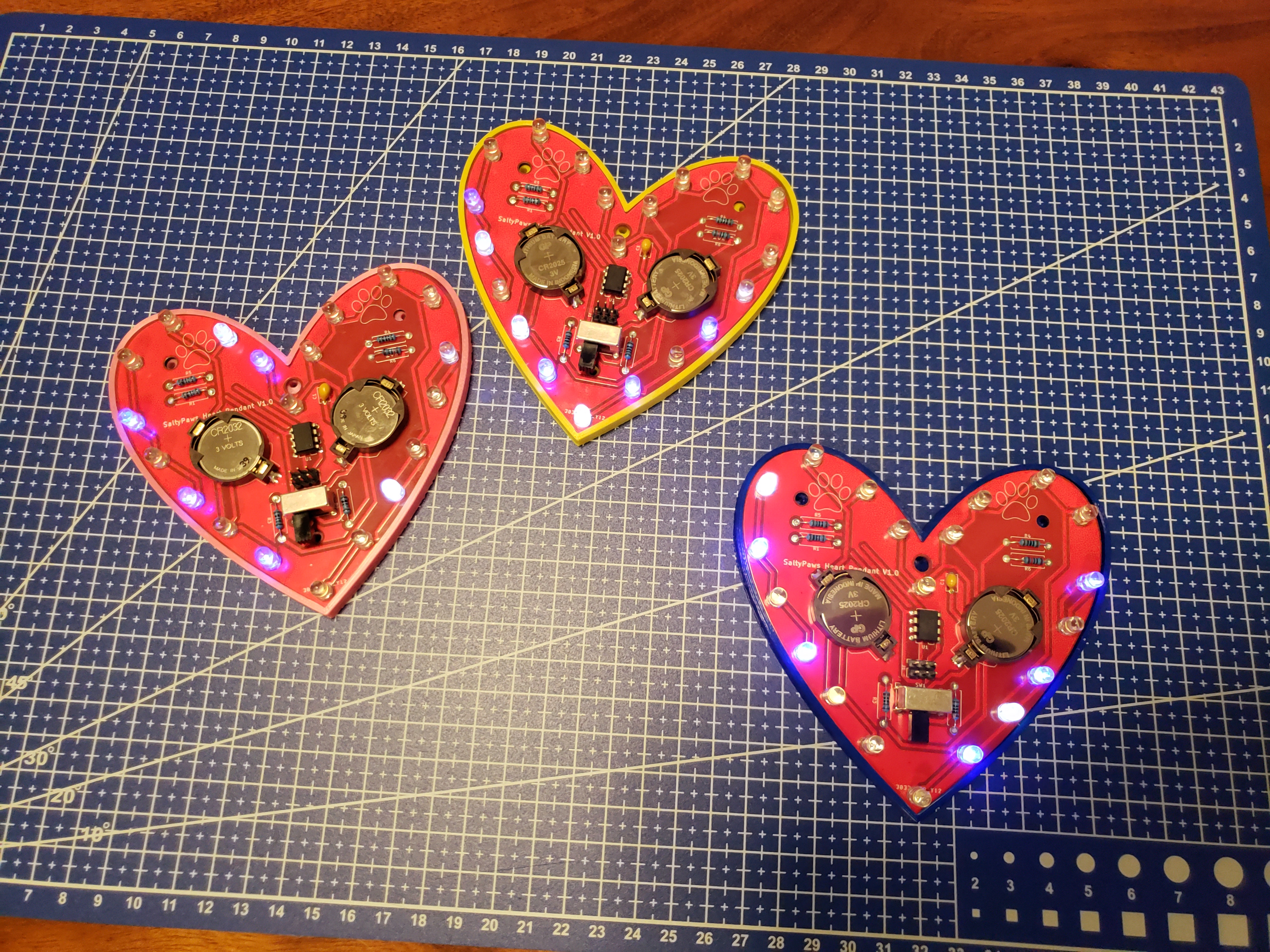
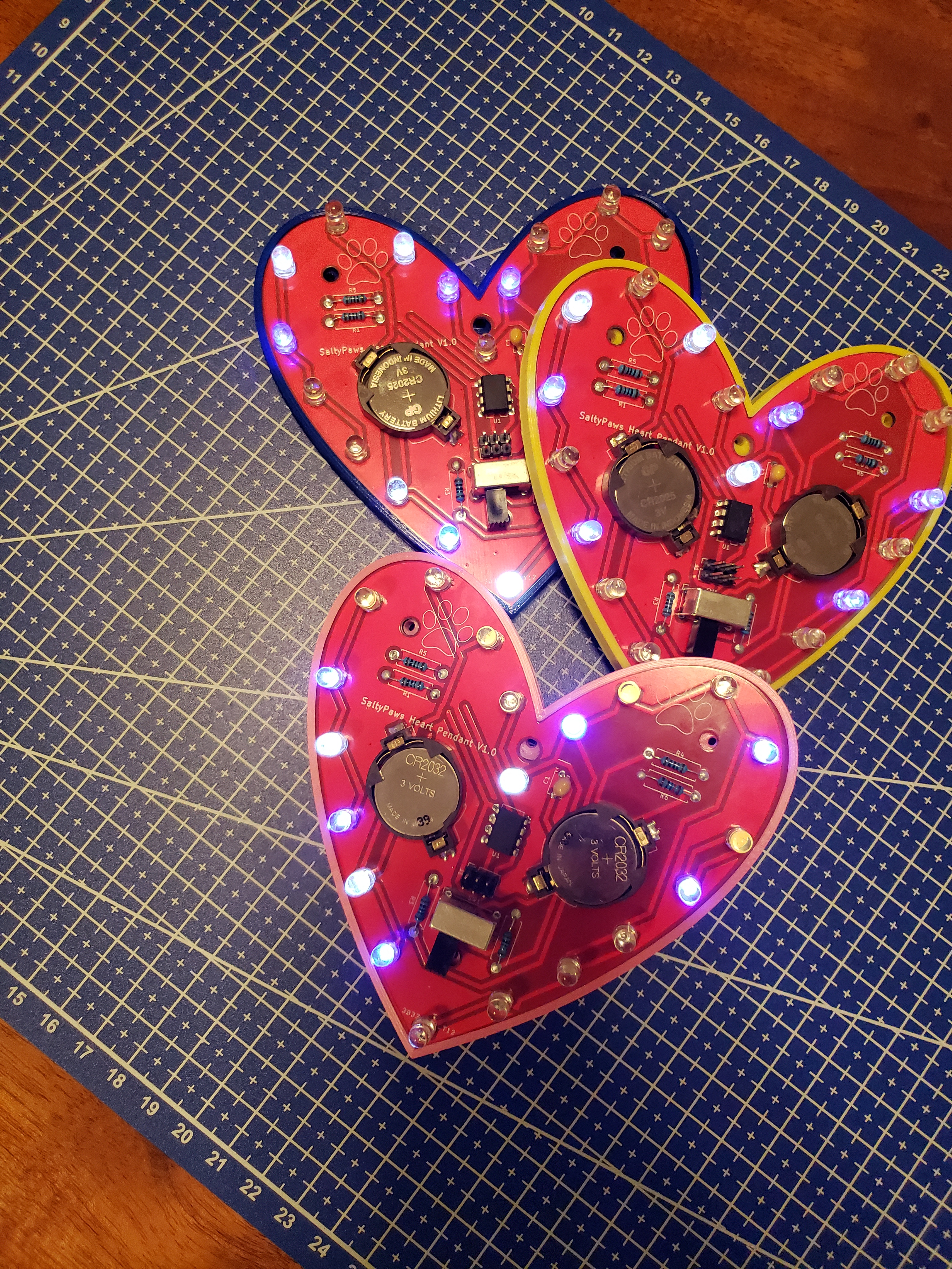
A large heart with 20 individually controllable LEDS using 4 pins on an ATtiny 45 with Charlieplexing This is an easy to solder project, as all components are trough hole, except for the large and easy to solder battery holder Who would not like to be pledged eternal love to by their valentine giving them a large blinky LED heart Pendant!

Large HEART PCB LED Pendant

Table of Contents

General Information

  • I developed this project, in order to introduce my daughters to electronics. This pendant can be used to introduce STEAM concepts at many levels. It can be used to introduce electronics, teach trough hole assembly/soldering and programming.
  • This is a basic demonstration of the Charlieplexing principle. The heart can be used stand alone or in a pendant.
  • I used FreeCAD in order to design the heart shape. Unfortunately at the time of designing, the offset tool was not available in FreeCAD (I know there are work arounds), and I completed the snap on case design using Fusion360.
  • I skipped the breadboard prototyping phase by using the proven Circuit design from designer2k2. The first version of the PCB worked as per design.
  • For printing the case, I used PLA, 40% infill and 0.2mm layer height. It easily snaps onto the PCB, and while the stand offs include m3 thread, the M3 x6mm bolts are not required as the 45 degrees edge on the case holds it in place. I would not reccomend using without case as the back of a trough hole PCB can be demanding blood like a Vampire from Transylvania.

Technologies Used

  • Ubuntu 20.10 OS
  • FreeCAD Realthunder branch (2021.10.15) for designing the heart shape
  • KiCad 5.99.0+really5.1.10+dfsg1-1, release build
  • Freerouting 1.4.5 (Current KiCad does not have an autorouter)
  • Fusion 360 for designing the heart case
  • Prusa slicer (1.4.0)
  • Arduino IDE 1.8.19 for flashing firmware and uploading the code.
  • Attiny core library (https://github.com/SpenceKonde/ATTinyCore)

Features

This project has the following awesome features:

  • uses 5 pins, in order to individually control 20 LEDs
  • The project uses trough hole components (with exception of easy to solder battery holder for easy assembly)
  • The 3D printed snap on case projects (young) fingers from the sharp spikes on the back of the trough hole PCB.
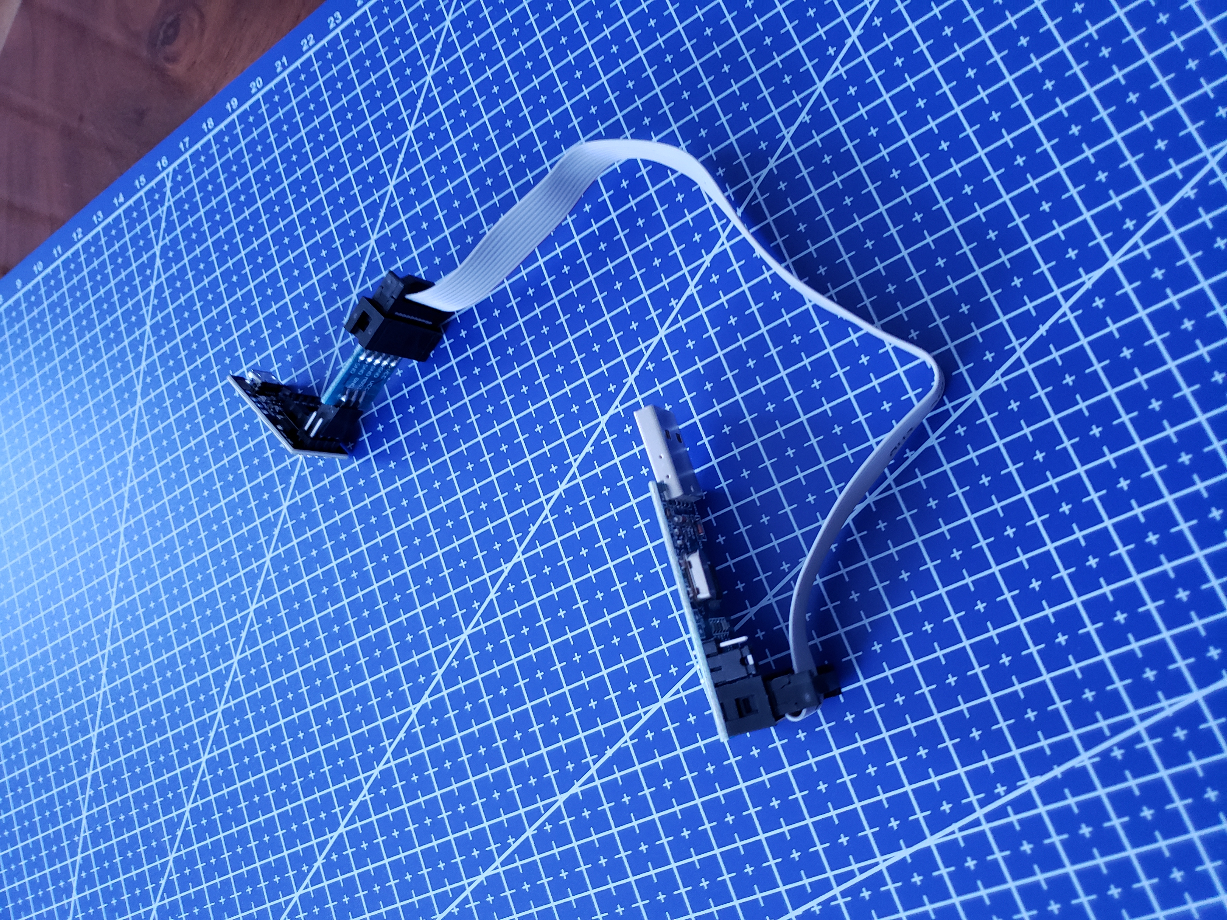
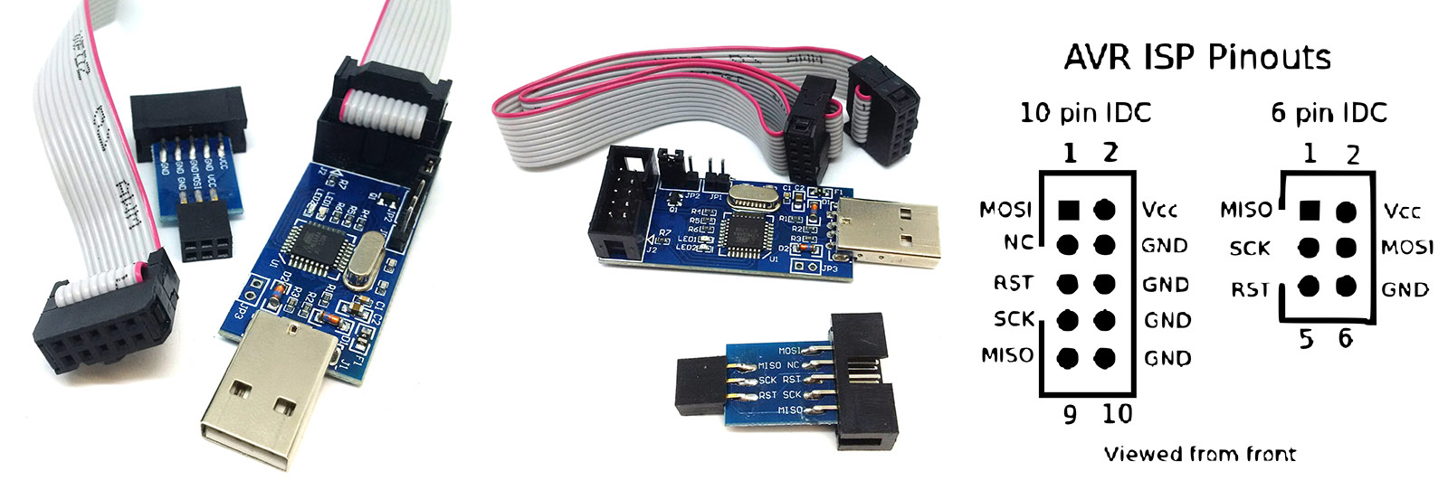
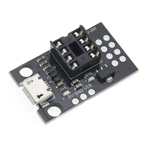
  • I used the HW-260 and USBASP in order to program the ATtiny45. However, the ATtiny45 can also be programmed using the connector on the PCB.

images

Large HEART PCB LED Pendant Large HEART PCB LED Pendant Large HEART PCB LED Pendant Large HEART PCB LED Pendant Large HEART PCB LED Pendant Large HEART PCB LED Pendant

Setup

  1. order PCB and parts (I used JLPCB, Aliexpress and Digikey)
  2. Program the ATtiny45 chip using the HW-260 & USBASP programmer. You will need to flash the bootloader @1 MHZ and upload the .ino code. (https://www.instructables.com/ATtiny13AATtiny25ATtiny45ATtiny85-Programming-With/) Hint: use ++ in order to upload using programmer.
  3. Start printing the snap on case.
  4. Heat up that iron and put the PCB together.
  5. Snap on the snap on case.
  6. Introduce STEAM or propose to your dearest.

Usage

Simply switch the heart on/off as required.

Project Status

Project is complete.

Room for Improvement

The heart is rather large for a pendant. I may develop a smaller version based on surface mount components in the future.

Room for improvement:

  • With the ATtiny 45 there is more memory space. It could be programmed to cycle trough more/longer patterns.
  • An eye could be added to the 3d printed snap fit case, for pendant usage. Currently only the 3mm hole is available, which may be a bit small for strings.
  • One of the M3 holes is covered by the switch. However, the case is snap fit and does not need the M3 hardware to stay in place.

Acknowledgements

Contact

Created by SaltyPaws - feel free to contact me!

License

This project is open source and available under the MIT License.

Parts

32
QtyValueFootprintReferences
20LEDLED_THT:LED_D5.0mm_ClearD1, D2, D3, D4, D5, D10, D11, D12, D13, D14, D15, D16, D17, D18, D19, D20 +4
575Resistor_THT:R_Axial_DIN0411_L9.9mm_D3.6mm_P12.70mm_HorizontalR1, R2, R3, R4, R5
2Battery_CellBattery:BatteryHolder_Keystone_1058_1x2032BT1, BT2
110kResistor_THT:R_Axial_DIN0411_L9.9mm_D3.6mm_P12.70mm_HorizontalR6
1ATTINY25-20SUPackage_DIP:DIP-8_W7.62mmU1
1CCapacitor_THT:C_Disc_D5.1mm_W3.2mm_P5.00mmC1
1ISPSocket_Strips:Socket_Strip_Straight_2x03_Pitch2.54mmJ1
1SW_SPDTButton_Switch_THT:SW_E-Switch_EG1224_SPDT_AngledSW1

Similar boards

  • 2 layers97.2 × 99.7 mm2D xmas tree01, the printed circuit board in 3D

    2D xmas tree01

    designer2k2/2d-xmas-tree

    a DIY flat christmas decoration with a ATtiny25, 20 led´s and a coin cell battery

    41 parts26MIT
  • 2 layers50 × 23.2 mmAnalog, the printed circuit board in 3D

    Analog

    hoglet67/RGBtoHDMI

    Bare-metal Raspberry Pi project that provides pixel-perfect sampling of Retro Computer RGB/YUV video and conversion to HDMI

    32 parts1kGPL-3.0
  • 2 layers136.8 × 54.2 mmRetropie zero, the printed circuit board in 3D

    Retropie zero

    hackclub/OnBoard

    💡 Join 1,000 teenagers and make your first PCB with a $100 grant!

    32 parts915
  • 2 layersMooltipass top, the printed circuit board in 3D

    Mooltipass top

    limpkin/mooltipass

    Github repository dedicated to the mooltipass project

    32 parts531
  • 2 layers16 × 20 mmESPKey, the printed circuit board in 3D

    ESPKey

    octosavvi/ESPKey

    Wiegand data logger, replay device and micro door-controller

    32 parts353GPL-2.0
  • 2 layers82 × 40.9 mmDisplay7447, the printed circuit board in 3D

    Display7447

    zmaker/arduino_cookbook

    gli sketch del nuovo progetto Arduino Cookbook e dei video di YouTube

    32 parts269
  • 2 layers40 × 38 mmShield, the printed circuit board in 3D

    Shield

    murexrobotics/electrical

    Highly integrated electronics design and printed circuit boards (PCBs) for the MATE ROV Competition. Attempt the impossible.

    32 parts192MIT
  • 2 layers47 × 39 mmQrss clock tx, the printed circuit board in 3D

    Qrss clock tx

    swharden/AVR-projects

    A collection of standalone AVR projects written in C

    32 parts184MIT

Questions

How big is the Heart Pendant v2 PCB?

It measures 202.4 × 142.2 mm and has 2 copper layers, 1.6 mm thick.

What parts does the Heart Pendant v2 use?

32 parts, built around the ATTINY25-20SU. The full list of its parts is on this page, with links to each part's symbol and footprint where PCBKit's library has them.

Where can I download the Heart Pendant v2 KiCad files?

From the SaltyPaws/Large-Heart-PCB-LED-Pendant repository on GitHub, at the commit this page was made from: the board is PCB design/Heart_Pendant_v2.kicad_pcb. PCBKit opens the board in the browser, with nothing to install.

Can I use the Heart Pendant v2 design in my own project?

Its repository publishes it under the MIT licence: you may reuse it on that licence's terms (keep the author's notice, and for a copyleft licence share your changes alike).