2 layers66.9 × 74.5 mm
 SaleemLab/LEDStimulation
code to run LED stimulation experiments
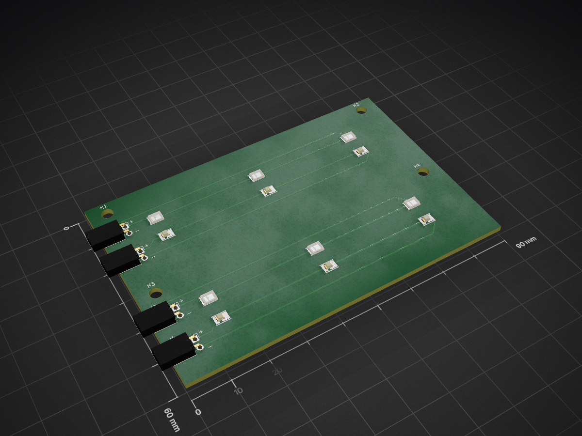
LED board is an open-source printed circuit board by SaleemLab, from the SaleemLab/LEDStimulation repository on GitHub. It is a 2-layer board of 90 × 60 mm with 20 parts on 16 nets, routed with 39 tracks and 0 vias.
Its parts include 12 diodes and 4 connectors.
An open-source, high-precision visual stimulation platform designed for visual neuroscience, sensory physiology, and human psychophysics. The system delivers temporally agile, multi-chromatic optical stimulation (e.g., Green for M-cones/rods and UV for S-cones, or custom multi-spectral arrays) with sub-millisecond precision.
https://github.com/user-attachments/assets/08af2269-a270-4899-ae75-62786a714254
Example stimulus: 2 Hz antiphase (Green / UV) sinusoidal flicker.
graph LR
    subgraph Host Software
        Bonsai[Bonsai Reactive Workflows]
        LSL[LabStreamingLayer / LabRecorder]
        MATLAB[MATLAB Calibration Suite]
    end

    subgraph Microcontroller Firmware
        MCU[Arduino Leonardo / Teensy 4.1]
        T1[Timer1: 16-bit PWM]
        T3[Timer3: CTC Interrupt Pacing]
        LUT[PROGMEM Gamma LUT]
    end

    subgraph Hardware & Optics
        Driver[Multi-Channel Driver Stage]
        LEDs[Dual-Channel LED Arrays]
        Enclosure[Magnetic Diffusion Enclosure / Glasses]
        Sensors[Photodiode / Power Meter / Eye Tracker]
    end

    Bonsai -- Serial ASCII (115200) --> MCU
    MATLAB -. Offline Calibration .-> LUT
MCU --> T1 & T3ArduinoCode/StimulusControlViaSerial_Leonardo_v8/StimulusControlViaSerial_Leonardo_v8.ino [blocked] in the Arduino IDE.115200 baud.s, 3000, 2.0, 0.0, 0.5, 0.8, 0.8Open Bonsai and load one of the pre-built visual stimulation workflows from BonsaiCode/ [blocked] (e.g., LEDstimulation_normal.bonsai or ManualMethodOfAdjustment.bonsai).
Comprehensive guides, schematics, and technical specifications are available in the docs/ directory:
├── ArduinoCode/                  # Microcontroller firmware (Leonardo v8, DDS, Teensy 4.1, IMU)
├── BonsaiCode/                   # Main Bonsai visual reactive workflows & stimulus CSVs
├── BonsaiForHumanExperiments/    # Dedicated human psychophysics Bonsai workflows
├── Calibration/                  # MATLAB scripts for radiometry, gamma LUTs & opsin calculations
├── Hardware/                     # CAD files (.stp, .stl, .ipt), KiCad PCB designs & driver schematics
│   ├── Enclosure/                # Baseplate CAD & 3D printed magnetic diffusion clamps
│   ├── glasses/                  # Pupil Labs Neon glasses boom arm & miniature diffuser
│   ├── LED_board/                # KiCad dual-channel LED array PCB
│   └── LED_board_humans/         # KiCad 3-colour LED array PCB (WIP redesign with layout improvements)
├── HumanExpAnalysis/             # MATLAB scripts for IMU movement and behavioural analysis
├── LabRecorderFiles/             # Multi-modal LabStreamingLayer (LSL) recording configurations
└── docs/ # Modular technical documentationDeveloped for scientific research applications. If you use this platform in your research, please cite this repository.
| Qty | Value | Footprint | References |
|---|---|---|---|
| 6 | LED | easyeda2kicad:LED-SMD_L3.5-W2.8-FD_WHITE-1 | D5, D6, D7, D13, D14, D15 |
| 6 | LED | easyeda2kicad:LED-SMD_L3.5-W2.8_RED | D1, D2, D3, D9, D10, D11 |
| 4 | MountingHole | MountingHole:MountingHole_3.2mm_M3 | H1, H2, H3, H4 |
| 1 | Green bank 1 | Connector_PinSocket_2.54mm:PinSocket_1x02_P2.54mm_Horizontal | J1 |
| 1 | Green bank 2 | Connector_PinSocket_2.54mm:PinSocket_1x02_P2.54mm_Horizontal | J3 |
| 1 | UV bank 1 | Connector_PinSocket_2.54mm:PinSocket_1x02_P2.54mm_Horizontal | J2 |
| 1 | UV bank 2 | Connector_PinSocket_2.54mm:PinSocket_1x02_P2.54mm_Horizontal | J4 |


atopile/atopile
Design circuit boards with code! ✨ Get software-like design reuse 🚀, validation, version control and collaboration in hardware; starting with electronics ⚡️

davidphilipbarr/Sweep
Sweep - a small promicro based keyboard inspired by the Ferris.

rusefi/rusefi
rusefi - GPL internal combustion engine control unit

hoglet67/RGBtoHDMI
Bare-metal Raspberry Pi project that provides pixel-perfect sampling of Retro Computer RGB/YUV video and conversion to HDMI

hackclub/OnBoard
💡 Join 1,000 teenagers and make your first PCB with a $100 grant!

FreeYourStream/freedeck-hardware
all the stuff you need to build your own FreeDeck
It measures 90 × 60 mm and has 2 copper layers, 1.6 mm thick.
20 parts. The full list of its parts is on this page, with links to each part's symbol and footprint where PCBKit's library has them.
From the SaleemLab/LEDStimulation repository on GitHub, at the commit this page was made from: the board is Hardware/LED_board/LED_board.kicad_pcb and its schematic Hardware/Constant_current_driver/Constant_current_driver.kicad_sch. PCBKit opens the board in the browser, with nothing to install.
Its repository states no licence, so its author keeps all rights: ask SaleemLab before reusing the design.