
2 layers
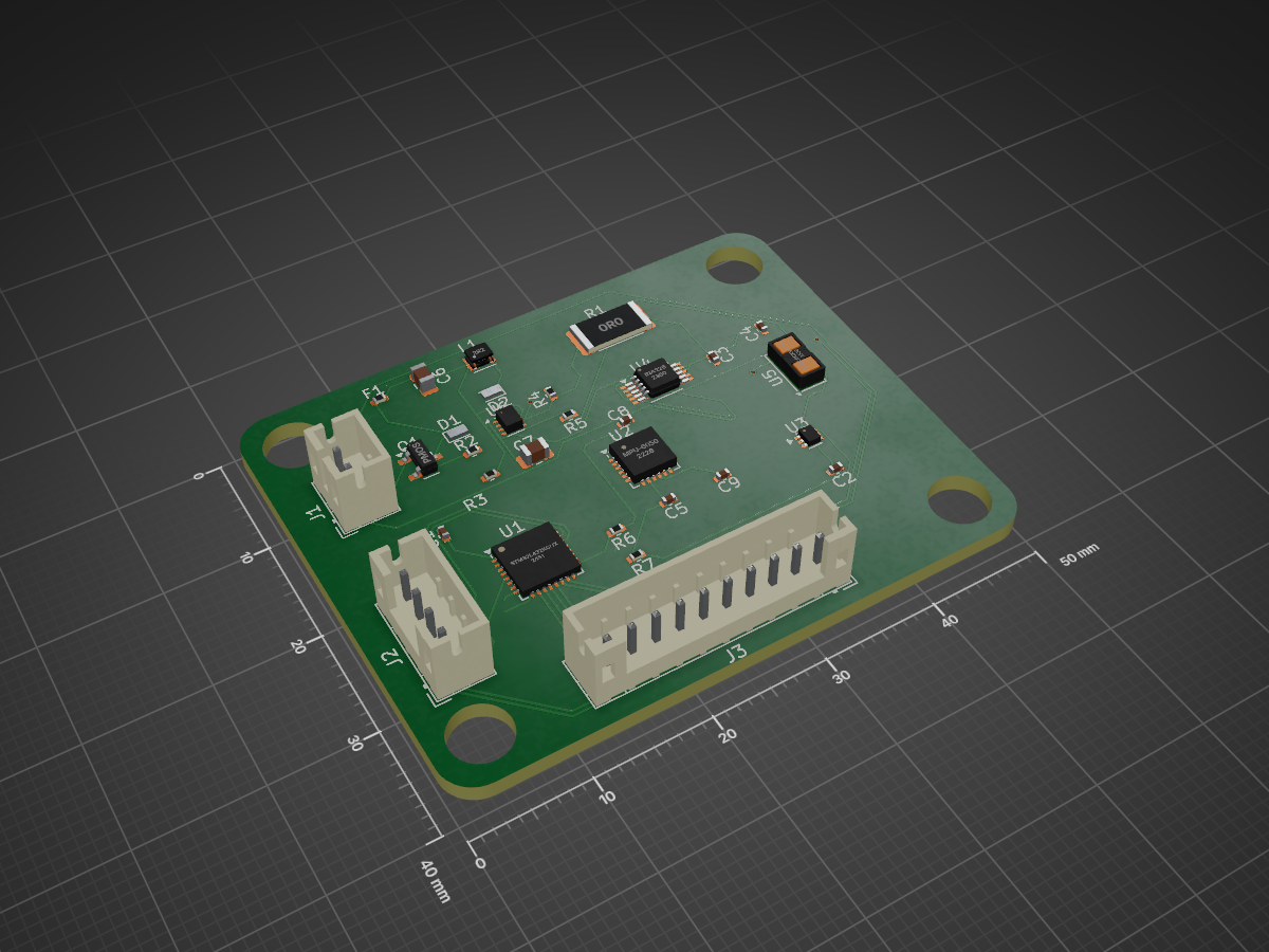
24-hour embedded systems design challenge submission.
SSTM is an open-source printed circuit board by SaiSundarP, from the SaiSundarP/Smart-Rover-Safety-Telemetry-Module repository on GitHub. It is a 2-layer board of 50 × 40 mm with 30 parts on 61 nets, routed with 248 tracks and 4 vias.
It is built around the MPU-6050, TPS62822DLC and PTVS5V0Z1USKYL. Its parts include 9 capacitors, 7 resistors, 6 ICs, 3 connectors and 2 diodes. It belongs with the STM32 boards of this library.


24-hour embedded systems design challenge submission.
Monitors battery voltage, current draw, internal temperature, motion/orientation (IMU), and one external proximity sensor. Fuses this into a fault state, streams telemetry to the rover's main computer over UART, and drives a local RGB status LED + buzzer for stand-alone warning even if the main computer is down or not listening.
RoverSafetyModule/
├── README.md                    <- you are here
├── docs/
│   ├── 01_architecture.md       <- block diagram, data/power/comm flow
│   ├── 02_component_selection.md<- every part + why, with datasheet links
│   ├── 03_calculations.md       <- power budget, dividers, shunt, decoupling, thermal
│   ├── 04_electronics_design.md <- schematic description, protection, pin maps
│   ├── 05_pcb_design.md         <- stack-up, placement, routing, dimensions
│   ├── 06_firmware.md           <- architecture, RTOS rationale, fault handling
│   ├── 07_testing_plan.md       <- bring-up + fault diagnosis plan
│   └── 08_tradeoffs.md          <- priorities, risks, V2 plan
├── firmware/                    <- FreeRTOS/STM32 HAL source (buildable skeleton)
├── bom/BOM.csv                  <- full bill of materials
├── datasheets/links.md          <- every datasheet referenced
└── pcb/ <- floorplan + stack-up notes (no KiCad GUI here — see below)Everything here is real, defensible engineering content: component choices,
calculations, pin-level connection tables, and working firmware architecture.
The one thing I could not produce in this environment is an actual
.kicad_pcb/.kicad_sch file, because that needs the KiCad GUI/EDA engine,
which isn't available here. Instead docs/04_electronics_design.md and
docs/05_pcb_design.md give you exact net-by-net connection tables and a
placement floorplan — this is normally the slow part (part selection +
deciding connections); transcribing it into KiCad schematic/PCB editor is
comparatively fast (roughly 1–2 hrs) and I'd suggest doing that next while the
rest of the report is fresh. I can also walk you through KiCad step-by-step
in real time if useful.
01_architecture.md and 02_component_selection.md — make sure you can
defend every choice out loud (that's what's being graded).04_electronics_design.md (connection tables).05_pcb_design.md (floorplan, stack-up, keepouts).firmware/ — it's a working task-based skeleton you can extend.07_testing_plan.md and 08_tradeoffs.md — these are pure writing,
fastest points to bank.| Qty | Value | Footprint | References |
|---|---|---|---|
| 5 | 100nF | Capacitor_SMD:C_0402_1005Metric | C1, C2, C3, C4, C5 |
| 2 | 100k | Resistor_SMD:R_0402_1005Metric | R2, R3 |
| 2 | 10uF | Capacitor_SMD:C_0805_2012Metric | C6, C7 |
| 2 | 2.2k | Resistor_SMD:R_0402_1005Metric | R6, R7 |
| 2 | PTVS5V0Z1USK | Diode_SMD:Nexperia_DSN1608-2_1.6x0.8mm | D1, D2 |
| 1 | 0.025 | Resistor_SMD:R_2512_6332Metric | R1 |
| 1 | 0.1uF | Capacitor_SMD:C_0402_1005Metric | C9 |
| 1 | 10k | Resistor_SMD:R_0402_1005Metric | R5 |
| 1 | 2.2nF | Capacitor_SMD:C_0402_1005Metric | C8 |
| 1 | 2.2uH | Inductor_SMD_Wurth:L_Wurth_WE-LQSH-2010 | L1 |
| 1 | 45.3k | Resistor_SMD:R_0402_1005Metric | R4 |
| 1 | Conn_01x02_Pin | Connector_JST:JST_PH_B2B-PH-K_1x02_P2.00mm_Vertical | J1 |
| 1 | Conn_01x04_Pin | Connector_JST:JST_PH_B4B-PH-K_1x04_P2.00mm_Vertical | J2 |
| 1 | Conn_01x10_Pin | Connector_JST:JST_PH_B10B-PH-K_1x10_P2.00mm_Vertical | J3 |
| 1 | INA226 | Package_SO:VSSOP-10_3x3mm_P0.5mm | U4 |
| 1 | MPU-6050 | Sensor_Motion:InvenSense_QFN-24_4x4mm_P0.5mm | U2 |
| 1 | PMOS | Package_TO_SOT_SMD:SOT-23 | Q1 |
| 1 | Polyfuse_Small | Fuse:Fuse_0402_1005Metric | F1 |
| 1 | STM32L432KCUx | Package_DFN_QFN:QFN-32-1EP_5x5mm_P0.5mm_EP3.45x3.45mm | U1 |
| 1 | TMP102xxDRL | Package_TO_SOT_SMD:SOT-563 | U3 |
| 1 | TPS62822DLC | Package_SON:Texas_VSON-HR-8_1.5x2mm_P0.5mm | U6 |
| 1 | VL53L0CXV0DH1 | Sensor_Distance:ST_VL53L1x | U5 |


hwkim3330/sfp-auto-ethernet
SFP modules that speak SGMII to the host and 100/1000BASE-T1, 1000BASE-T or 10BASE-T1S to the world (KiCad)

teejaytiger/FPGBA
Full overhaul of the GBA mainboard to free ourselves from supply chain death


emertcakir/OpenAirScope
Open-source air quality and environmental monitoring node with STM32H743 + ESP32-C3, LoRaWAN, RS485, USB-C, Li-ion charging, and multi-sensor support.

emertcakir/OmniProbe
Open-source SWD, JTAG, UART, SPI, I2C and Logic Analyzer platform powered by RP2040

kwiecinski/BMS-and-offgrid-photovoltaic-management-system
Project contains BMS for lead-acid batteries and ESP-based board used to pull information from EASUN offgrid inverter, energy meters and sensors.
It measures 50 × 40 mm and has 2 copper layers, 1.6 mm thick.
30 parts, built around the MPU-6050, TPS62822DLC and PTVS5V0Z1USKYL. The full list of its parts is on this page, with links to each part's symbol and footprint where PCBKit's library has them.
From the SaiSundarP/Smart-Rover-Safety-Telemetry-Module repository on GitHub, at the commit this page was made from: the board is pcb/SSTM/SSTM.kicad_pcb and its schematic pcb/SSTM/SSTM.kicad_sch. PCBKit opens the board in the browser, with nothing to install.
Its repository states no licence, so its author keeps all rights: ask SaiSundarP before reusing the design.