
2 layers65 × 50 mm
Mecha Dev Expander
SolidwareGit/Modular-GP2040-Dev-Board
This is a development board for the RP2040 to enable creation of a modular GP2040-CE, using I2C, for fightsticks or other controller peripherals
30 parts1CC0-1.0

 SP6GK/TCA9554_STM32_GPIO_Expander
STM32 HAL driver for TCA9554 GPIO expander + evaluation board.
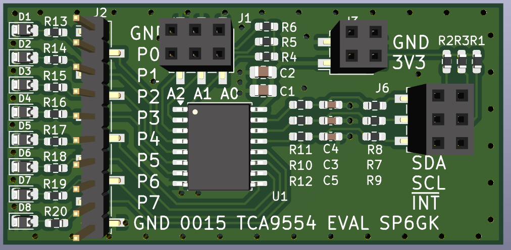
0015 TCA9554 GPIO rev01a is an open-source printed circuit board by SP6GK, from the SP6GK/TCA9554_STM32_GPIO_Expander repository on GitHub, published under the AGPL-3.0 licence. It is a 2-layer board of 60 × 29 mm with 38 parts on 30 nets, routed with 159 tracks and 69 vias.
It is built around the TCA9554DW. Its parts include 20 resistors, 8 diodes, 5 capacitors, 4 connectors and 1 IC.
STM32 HAL driver for the TCA9554 8-bit I/O expander. This is a useful IC that I find more capable and easier to use than the common PCF8574.
The project includes:
Copy the .c and .h from demo project to your project:
Configure the I2C peripheral in STM32CubeMX and initialize the driver:
#include "TCA9554.h"

TCA9554_HandleTypeDef GPIO_expander1 =
{
    .hi2c = &hi2c1,              // CubeMX I2C configuration
    .address = TCA9554_ADDRESS,  // Defined in header file
    .io_configuration = 0x00,    // 0 = Output, 1 = Input
    .io_states = 0x00,           // 0 = Low, 1 = High
    .pol_inversion = 0x00        // No polarity inversion
};

TCA9554_init(&GPIO_expander1);
By default, all pins are configured as inputs. Set io_configuration to configure individual pins: for example, 0b01010101 configures P0, P2, P4, and P6 as outputs, and P1, P3, P5, and P7 as inputs.
uint8_t read_status = 0;
bool pin_status[8] = {0};

//Write to specific pin
for(int i = 0; i < 8; i++){
		  TCA9554_set_pin(&GPIO_expander1, i, true);
		  HAL_Delay(100);
	  }


//Write state of all pins at once
for(uint8_t counter = 0; counter < UINT8_MAX; counter++){
  TCA9554_write(&GPIO_expander1, TCA9554_OUT_REG, counter);

  read_status = TCA9554_read(&GPIO_expander1, TCA9554_IN_REG);	//Read status of every pin
  for(uint8_t i = 0; i < 8; i++){
  pin_status[i] = TCA9554_read_pin(&GPIO_expander1, i); //Read status of single pin
}KiCad evaluation board design for the TCA9554 I/O expander.
The hardware project includes the schematic and PCB design files, organized under the ECAD/ directory.
Documents/ includes interactive BOM and .pdf schematic.
| Qty | Value | Footprint | References |
|---|---|---|---|
| 8 | 750 | Resistor_SMD:R_0603_1608Metric_Pad0.98x0.95mm_HandSolder | R13, R14, R15, R16, R17, R18, R19, R20 |
| 8 | LED_Small | Diode_SMD:D_0805_2012Metric_Pad1.15x1.40mm_HandSolder | D1, D2, D3, D4, D5, D6, D7, D8 |
| 6 | 100 | Resistor_SMD:R_0603_1608Metric_Pad0.98x0.95mm_HandSolder | R7, R8, R9, R10, R11, R12 |
| 3 | 100p | Capacitor_SMD:C_0603_1608Metric_Pad1.08x0.95mm_HandSolder | C3, C4, C5 |
| 3 | 10k | Resistor_SMD:R_0603_1608Metric_Pad0.98x0.95mm_HandSolder | R4, R5, R6 |
| 3 | 3k9 | Resistor_SMD:R_0603_1608Metric_Pad0.98x0.95mm_HandSolder | R1, R2, R3 |
| 2 | 1u | Capacitor_SMD:C_0805_2012Metric_Pad1.18x1.45mm_HandSolder | C1, C2 |
| 2 | Conn_02x03_Odd_Even | Connector_PinSocket_2.54mm:PinSocket_2x03_P2.54mm_Vertical_SMD | J1, J6 |
| 1 | Conn_01x10 | Connector_PinHeader_2.54mm:PinHeader_1x10_P2.54mm_Vertical_SMD_Pin1Left | J2 |
| 1 | Conn_02x02_Odd_Even | Connector_PinSocket_2.54mm:PinSocket_2x02_P2.54mm_Vertical_SMD | J3 |
| 1 | TCA9554DW | Package_SO:SOIC-16W_7.5x10.3mm_P1.27mm | U1 |
SolidwareGit/Modular-GP2040-Dev-Board
This is a development board for the RP2040 to enable creation of a modular GP2040-CE, using I2C, for fightsticks or other controller peripherals

joeycastillo/The-Open-Book
For details on how to build, test and use Open Book, I've made documentation available here.


hackclub/OnBoard
💡 Join 1,000 teenagers and make your first PCB with a $100 grant!


Ardumower/ardumower
Develop an open source robotic lawn mower (HW+SW reference platform)

CRImier/MyKiCad
My KiCad boards. Can't be bothered uploading individually anymore, so here you go.

It measures 60 × 29 mm and has 2 copper layers, 1.6 mm thick.
38 parts, built around the TCA9554DW. The full list of its parts is on this page, with links to each part's symbol and footprint where PCBKit's library has them.
From the SP6GK/TCA9554_STM32_GPIO_Expander repository on GitHub, at the commit this page was made from: the board is ECAD/KiCad_0015_TCA9554_GPIO_rev01a/0015_TCA9554_GPIO_rev01a.kicad_pcb and its schematic ECAD/KiCad_0015_TCA9554_GPIO_rev01a/0015_TCA9554_GPIO_rev01a.kicad_sch. PCBKit opens the board in the browser, with nothing to install.
Its repository publishes it under the AGPL-3.0 licence: you may reuse it on that licence's terms (keep the author's notice, and for a copyleft licence share your changes alike).