4 layers56.3 × 68.4 mm
Test Stand Power Monitor
ekatynski/Test-Stand-Power-Monitor
A small board for cheaply and easily monitoring a motor test stand for a host of data types.
70 parts
 Ruzz-1010/Project-FALCON-011
thesis proposal system
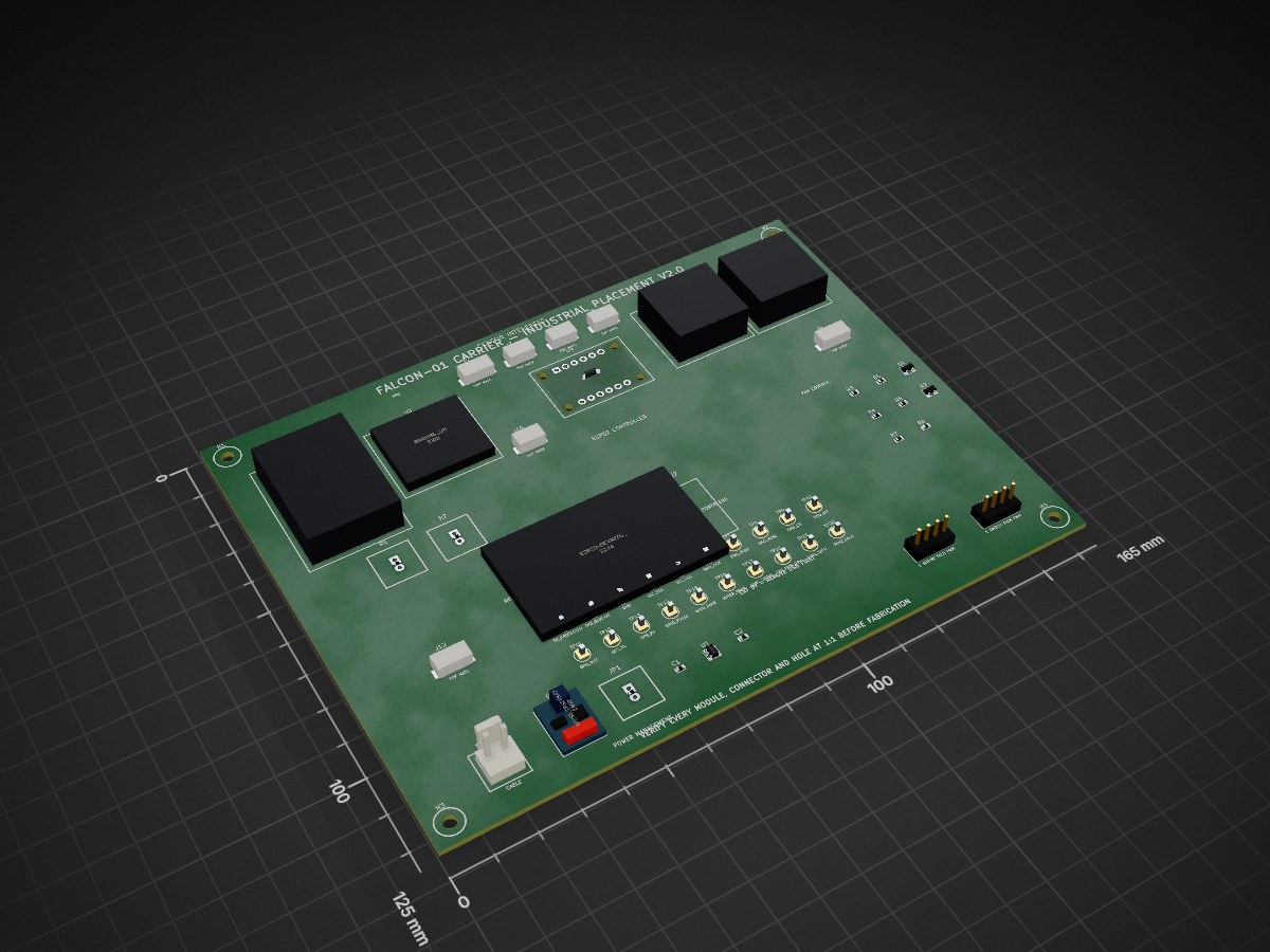
FALCON CARRIER is an open-source printed circuit board by Ruzz-1010, from the Ruzz-1010/Project-FALCON-01 repository on GitHub. It is a 2-layer board of 165 × 125 mm with 55 parts on 26 nets.
It is built around the AP2112K-3.3TRG1, BM03B-GHS-TBT and BM04B-GHS-TBT, with the B2P-VH-FB-B among its other parts. Its parts include 13 connectors, 8 resistors, 5 ICs, 2 capacitors and 2 transistors. It belongs with the radio and wireless boards and the ESP32 boards of this library.


Current revision note (2026-10-10): Use the DOST major revision baseline in
docs/REVISION_2026-10-10.mdunless this file is explicitly archived. The active proposal core is a compact ESP32-based buoy with water pressure sensing, wind speed/direction sensing, GPS for exact position and security, battery + solar power, and Wi-Fi/LTE internet communication. LoRa, large Bay Station hardware, tall tower layouts, and continuous every-second uploads are legacy or optional fallback assumptions.
HISTORICAL ELECTRICAL DRAFT: This project predates the Bay Station/LTE baseline and still contains a BNO085 footprint plus Orange Pi/USB assumptions. Do not fabricate it. Rebuild the release schematic/PCB only after exact sensors, LTE modem/power/interface, connectors, and mechanical interfaces are approved.
Status: native KiCad pre-schematic and placement-zone draft; not approved for fabrication.
This KiCad project will implement a serviceable low-voltage carrier for the ESP32 DevKit and selected sensor breakouts. It intentionally excludes the raw 12.8 V battery, solar-panel, MPPT, and high-current distribution paths.
The board receives protected, regulated 5 V from the dedicated ESP32 buck branch. It distributes 5 V, regulated 3.3 V, logic ground, and the validated sensor buses. The Orange Pi retains its own 5 V supply and connects to the ESP32 through USB during Phase 1.
High-current battery and solar conductors connect directly to the appropriately rated INA260 breakout terminals outside the carrier copper path. Only INA260 logic power and I2C reach the carrier.
The current control deck is documented as 250 x 210 mm inside the latest rectangular-pod concept. The first carrier outline shall be no larger than 165 x 125 mm, leaving service and connector clearance. This is a planning envelope only: mounting-hole coordinates and final outline remain TBD until the enclosure and modules are physically measured.
Native KiCad 10 .kicad_pro, .kicad_sch, and .kicad_pcb files are present.
The board contains a 165 x 125 mm compact-preview outline and labeled placement zones,
not final footprints or routing. Do not manufacture from placeholder geometry
or exported pictures.
Schematic v1.0 is organized into Power Management, ESP32 Controller, Sensor
Interfaces, Communication, and Debug & Expansion blocks. It adds the documented
battery protection chain, external-MPPT solar boundary, power-only service
USB-C, status/program controls, eight release test points, and connector-only
UART edge interface. The external edge computer is not part of the PCB.
generate_schematic.py reproducibly rebuilds the native schematic and project
symbol library. The current placement PCB predates v1.0 and must not be routed
until schematic-to-PCB synchronization and the remaining part-selection gates
are completed.
PCB placement v0.7 contains manufacturer-CAD module sockets, official-catalog
JST GH/VH connector geometry, named-net pads, four provisional M3 mounting holes, and an ESP32 antenna
keep-out. generate_pcb.py reproducibly builds this placement. The current DRC
result is zero geometry/rule violations and 64 expected unconnected ratsnest
items. Those connections must remain visible until deliberate copper routing;
they are not to be suppressed or described as a finished PCB.
Industrial placement v2.0 preserves the existing PCB pad/net assignments and
the 165 x 125 mm outline while reorganizing all 55 footprints. GPS, BNO085,
pressure, wind-speed, wind-direction, temperature, battery-monitor, and
solar-monitor interfaces follow one outward-facing sensor edge; the ESP32 is
centered; power follows one lower-edge service flow; communication/test points
form an accessible bank; and fan circuitry occupies a separate corner.
professional_placement.py reapplies this placement deterministically. This is
a routing-ready placement candidate, not a fabrication release: the physical
footprint, enclosure, and part-selection gates still apply.
Placement v0.3 reorganizes the same validated nets into professional functional zones: field connectors on the left service edge, I2C modules in an addressable distribution column, pull-ups beside their inputs, BNO085/GPS in the quiet control area, ESP32 at the antenna edge, and power/fan/service components at the bottom right. This reduces ratsnest crossing before routing without pretending that the provisional footprints are final.
Placement v0.4 adds 18 schematic-synchronized, through-hole service test points for both rails, ground, I2C, BNO085 SPI/control, GPS UART, external sensor inputs, and fan PWM. They are grouped and labeled in an accessible service bank for safe bench bring-up; this does not remove the footprint-validation gate.
Placement v0.5 replaces the generic U3, J3, J4, J5, and U4 envelopes with manufacturer-CAD socket geometry for the selected Adafruit BNO085, Ultimate GPS, two INA260 boards, and ADS1115 STEMMA QT board. Header pads, module outlines, and mounting holes now use the official board datums. U2 was also rotated so its antenna end actually faces the right-edge keep-out. Receiving and 1:1 checks are still mandatory before routing or fabrication.
Placement v0.6 adds the reviewed external-input protection blocks: J1 raw 5 V, U6 TPS25947-family eFuse candidate, and JP1 external-power enable. The normal deployment remains USB powered with JP1 open. The added silkscreen explicitly requires USB removal before JP1 is fitted. Protection values remain blocked by load, buck, transient, and thermal measurements.
Reference map:
| Reference | Function |
|---|---|
| U1 | 5 V to 3.3 V regulator placeholder |
| U2 | ESP32 DevKit carrier interface |
| U3 | BNO085 SPI breakout |
| U4 | ADS1115 wind-vane ADC |
| U5 | Fan MOSFET-driver placeholder |
| U6 | TPS25947-family external-input eFuse candidate |
| JP1 | External-power enable shunt; USB must be unplugged when fitted |
| J1 | Protected 5 V input |
| J2–J6 | Historical Bar02, GPS, two INA260 logic links, MCP9808; J2 requires HPT604 loop redesign |
| J7–J10 | Anemometer, wind vane, DS18B20, leak sensor |
| J11/J13 | Independent four-wire PWM fan outputs |
| J12 | Service I2C |
| R1–R2 | Wind-pulse 10 kOhm and OneWire 4.7 kOhm pull-ups |
| H1–H4 | Provisional M3 mounting holes |
| TP1–TP18 | Labeled power, bus, UART, sensor-input, and PWM test points |
Every footprint still requires a purchased-part check on a 1:1 print. The JST GH/VH geometry is captured from the official manufacturer catalogs, but mating direction, assembly clearance, and received-part revision must still be signed off before fabrication.
The next release gate is FOOTPRINT_VALIDATION.md.
Record measurements in footprint_measurements.csv; do not start final copper
routing while the critical rows remain PENDING.
Use PHYSICAL_FIT_CHECKLIST.md with a true 100%-scale
print to capture the required module, connector, cable, and enclosure checks.
Run python3 export_physical_fit_sheet.py, then print
FALCON_CARRIER_PHYSICAL_FIT_A4.svg on A4 portrait at 100% / Actual size.
Verify its 50 mm calibration bar before trusting the footprint overlay.
On Linux Mint, a matching A4 PDF can be rebuilt with
convert -density 300 FALCON_CARRIER_PHYSICAL_FIT_A4.svg -units PixelsPerInch FALCON_CARRIER_PHYSICAL_FIT_A4.pdf.
Official product dimensions and CAD-derived hole/header coordinates gathered for that gate are recorded in MANUFACTURER_DIMENSION_RESEARCH.md. These references reduce guesswork but do not replace the receiving and 1:1 checks.
KiCad routing classes and the required routing sequence are documented in ROUTING_PLAN.md. The project now applies wider power/fan rules and separate sensor-bus/external-sensor clearances automatically.
U2 is now locked to the official Espressif ESP32-DevKitC V4 with
ESP32-WROOM-32E 38-pad geometry and header numbering. The official Espressif
KiCad footprint and its license are stored under vendor/; the generated board
uses the same pad pitch, row spacing, outline, USB end, and approved functional
pad mapping. Physical receiving/1:1 validation is still required.
Use these source registers during capture:
docs/PCB_VALIDATION_REGISTER.mddocs/PCB_VALIDATION_REGISTER.md.Local lightweight VRML envelopes are stored in models/ and attached by the
PCB generator. Run python3 generate_3d_models.py, regenerate the PCB, open
FALCON_CARRIER.kicad_pcb in KiCad PCB Editor, then press Alt+3. These
models communicate placement and approximate component volume only; they are
not manufacturer STEP models and must not be used for enclosure tolerancing.
| Qty | Value | Footprint | References |
|---|---|---|---|
| 4 | BM03B-GHS-TBT | JST_GH_03P_TOP_BM03B-GHS-TBT | J7, J8, J9, J10 |
| 4 | M3 PROVISIONAL | FALCON_PROVISIONAL_M3_HOLE | H1, H2, H3, H4 |
| 3 | BM04B-GHS-TBT | JST_GH_04P_TOP_BM04B-GHS-TBT | J2, J6, J12 |
| 2 | 470531000 | MOLEX_470531000_4PIN_FAN_HEADER | J11, J13 |
| 1 | 2N7002_FAN1_PWM | SOT-23_2N7002 | Q1 |
| 1 | 2N7002_FAN2_PWM | SOT-23_2N7002 | Q2 |
| 1 | 3V3_SENSOR | FALCON_TEST_POINT_THT | TP2 |
| 1 | 5V_PROTECTED | FALCON_TEST_POINT_THT | TP1 |
| 1 | ADS1115_0X48 | FALCON_LOCKED_ADS1115_0X48 | U4 |
| 1 | AP2112K-3.3TRG1 | SOT-25_AP2112K | U1 |
| 1 | B2P-VH-FB-B | JST_VH_02P_B2P-VH-FB-B | J1 |
| 1 | BNO085_SPI | FALCON_LOCKED_BNO085_SPI | U3 |
| 1 | BNO_CS | FALCON_TEST_POINT_THT | TP9 |
| 1 | BNO_INT | FALCON_TEST_POINT_THT | TP10 |
| 1 | BNO_MISO | FALCON_TEST_POINT_THT | TP7 |
| 1 | BNO_MOSI | FALCON_TEST_POINT_THT | TP8 |
| 1 | BNO_RST | FALCON_TEST_POINT_THT | TP11 |
| 1 | BNO_SCK | FALCON_TEST_POINT_THT | TP6 |
| 1 | EFUSE_TPS25947_TBD | FALCON_PROVISIONAL_EFUSE_TPS25947_TBD | U6 |
| 1 | ESP32-DevKitC_V4_WROOM-32E | FALCON_LOCKED_ESP32_DEVKITC_V4 | U2 |
| 1 | EXT_POWER_ENABLE | FALCON_PROVISIONAL_EXT_POWER_ENABLE | JP1 |
| 1 | FAN1_GATE_100R | R_0603_1608Metric | R3 |
| 1 | FAN1_GATE_PULLDOWN_100K | R_0603_1608Metric | R5 |
| 1 | FAN1_TACH | FALCON_TEST_POINT_THT | TP19 |
| 1 | FAN1_TACH_PULLUP_10K | R_0603_1608Metric | R7 |
| 1 | FAN2_GATE_100R | R_0603_1608Metric | R4 |
| 1 | FAN2_GATE_PULLDOWN_100K | R_0603_1608Metric | R6 |
| 1 | FAN2_TACH | FALCON_TEST_POINT_THT | TP20 |
| 1 | FAN2_TACH_PULLUP_10K | R_0603_1608Metric | R8 |
| 1 | FAN_PWM_GPIO | FALCON_TEST_POINT_THT | TP18 |
| 1 | GND | FALCON_TEST_POINT_THT | TP3 |
| 1 | GPS_RX | FALCON_TEST_POINT_THT | TP13 |
| 1 | GPS_TX | FALCON_TEST_POINT_THT | TP12 |
| 1 | GPS_UART | FALCON_LOCKED_GPS_UART | J3 |
| 1 | I2C_SCL | FALCON_TEST_POINT_THT | TP5 |
| 1 | I2C_SDA | FALCON_TEST_POINT_THT | TP4 |
| 1 | INA260_BAT_LOGIC | FALCON_LOCKED_INA260_BAT_LOGIC | J4 |
| 1 | INA260_SOLAR_0X41 | FALCON_LOCKED_INA260_SOLAR_0X41 | J5 |
| 1 | LDO_INPUT_1UF_X7R | R_0603_1608Metric | C1 |
| 1 | LDO_OUTPUT_1UF_X7R | R_0603_1608Metric | C2 |
| 1 | LEAK_SIGNAL | FALCON_TEST_POINT_THT | TP17 |
| 1 | PULLUP_10K | FALCON_PROVISIONAL_PULLUP_10K | R1 |
| 1 | PULLUP_4K7 | FALCON_PROVISIONAL_PULLUP_4K7 | R2 |
| 1 | WATER_TEMP | FALCON_TEST_POINT_THT | TP16 |
| 1 | WIND_PULSE | FALCON_TEST_POINT_THT | TP14 |
| 1 | WIND_VANE | FALCON_TEST_POINT_THT | TP15 |
ekatynski/Test-Stand-Power-Monitor
A small board for cheaply and easily monitoring a motor test stand for a host of data types.


krups/RockSatX-GHOST-Hardware
Hardware files for the 2025 RockSat-X GHOST mission

lulf/legobots
Repository with various firmware and software for lego-related projects:


getriscvyy/divesync-heavy
A syringe-actuated buoyancy control device developed at the Bio-Inspired Robotics and Controls Lab at University of Houston.

Caped-Crussader/Gyro-Accel-Baro-Breakout-Board
A compact multi-sensor breakout board combining three high-performance sensors on a single PCB with a shared SPI bus, onboard power regulation, and dual JST-GH connectors.
It measures 165 × 125 mm and has 2 copper layers, 1.6 mm thick.
55 parts, built around the AP2112K-3.3TRG1, BM03B-GHS-TBT, BM04B-GHS-TBT and B2P-VH-FB-B. The full list of its parts is on this page, with links to each part's symbol and footprint where PCBKit's library has them.
From the Ruzz-1010/Project-FALCON-01 repository on GitHub, at the commit this page was made from: the board is hardware/kicad/FALCON_CARRIER/FALCON_CARRIER.kicad_pcb and its schematic hardware/kicad/FALCON_CARRIER/FALCON_CARRIER.kicad_sch. PCBKit opens the board in the browser, with nothing to install.
Its repository states no licence, so its author keeps all rights: ask Ruzz-1010 before reusing the design.