4 layers68 × 45 mm
Interface DAC
nonameCCC/PHASE-1
A compact modularized audio DAC & Headphone Amplifier.
146 partsGPL-3.0

 Reutronix/uni-dap-v3
UniDAP hardware repo
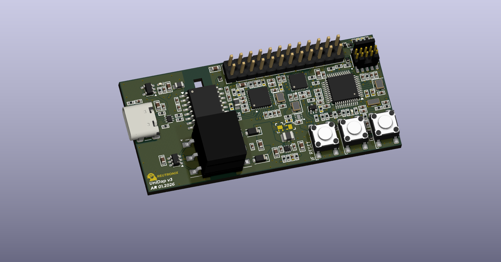
Uni dap is an open-source printed circuit board by Reutronix, from the Reutronix/uni-dap-v3 repository on GitHub. It is a 4-layer board of 66.2 × 30.9 mm with 149 parts on 134 nets, routed with 1,087 tracks and 187 vias.
It is built around the CH347F, SN6505ADBV and TPS62A02ADRL, with the ADUM4160BRW, TXB0102DCU and USBLC6-2P6 among its other parts. Its parts include 54 capacitors, 50 resistors, 16 diodes, 10 ICs and 4 connectors. It belongs with the interfaces and adapters boards and the STM32 boards of this library.


Galvanically isolated CMSIS-DAP debug probe with USB-to-I²C/SPI/GPIO bridging.
UniDAP is an open hardware debug/programming probe. It combines a full USB-isolated CMSIS-DAP probe (SWD + UART) with a USB-to-I²C/SPI/GPIO bridge, so a single USB-C cable gives you target programming, a serial console, general-purpose bus access, and isolated power — all on the far side of a galvanic isolation barrier.
A single USB-C connection is isolated for both data and power, then fanned out on the isolated side to the STM32 (DAPLink) and the CH347 through a 2-port USB hub.
flowchart TB
    subgraph HOST["Host side (non-isolated)"]
        USBC["USB-C"]
    end

    subgraph BARRIER["Isolation barrier"]
        ADUM["ADuM4160<br/>USB isolator<br/>+ current limit / reverse-current protection"]
        SN["SN6505ADBV + transformer<br/>isolated 5 V supply"]
    end

    subgraph ISO["Isolated side"]
        HUB["CY7C65634<br/>2-port USB hub"]
        STM["STM32F103<br/>DAPLink (SWD + UART)"]
        CH["CH347F<br/>USB → I²C / SPI / GPIO"]
        H20["24-pin 2.54 mm<br/>output header"]
        H10["10-pin 1.27 mm<br/>Cortex Debug"]
    end

    USBC --> ADUM --> HUB
    USBC --> SN
    SN -. isolated 5 V .-> ISO
    HUB --> STM
    HUB --> CH
    STM -->|SWD + UART| H20
    STM -->|SWD| H10
CH -->|I²C / SPI / GPIO| H20| Function | Part |
|---|---|
| Main MCU / debug probe | STM32F103 (running DAPLink) |
| USB → I²C / SPI / GPIO bridge | WCH CH347F |
| USB isolator | Analog Devices ADuM4160 |
| Isolated 5 V supply | TI SN6505ADBV push-pull transformer driver + transformer |
| USB hub (isolated side) | Cypress CY7C65634 (2-port) |
| Gated power output | ideal-diode switch, GPIO-controlled |
| UART level shifter (optional) | U502 (target-referenced) |
The main fan-out header carries the SWD programming signals from the STM32, the DAPLink UART, the CH347 I²C/SPI/GPIO lines, and the isolated power rails (5 V, 3.3 V, and the gated VOUT). It uses an odd/even footprint: odd pins on one row, even pins on the other, with pin 1 and pin 2 side by side. Refer to on-board bottom side silkscreen.
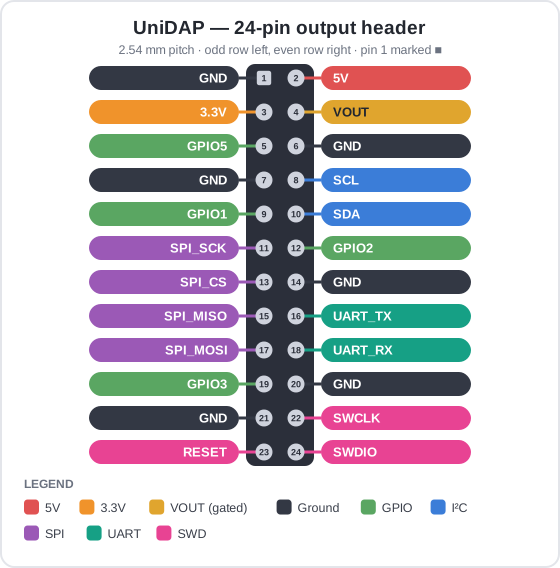
| Pin | Signal | Group | Pin | Signal | Group | |
|---|---|---|---|---|---|---|
| 1 | GND | Ground | 2 | 5V | Power | |
| 3 | 3.3V | Power | 4 | VOUT | Gated power | |
| 5 | GPIO5 | GPIO | 6 | GND | Ground | |
| 7 | GND | Ground | 8 | SCL | I²C | |
| 9 | GPIO1 | GPIO | 10 | SDA | I²C | |
| 11 | SPI_SCK | SPI | 12 | GPIO2 | GPIO | |
| 13 | SPI_CS | SPI | 14 | GND | Ground | |
| 15 | SPI_MISO | SPI | 16 | UART_TX | UART | |
| 17 | SPI_MOSI | SPI | 18 | UART_RX | UART | |
| 19 | GPIO3 | GPIO | 20 | GND | Ground | |
| 21 | GND | Ground | 22 | SWCLK | SWD | |
| 23 | RESET | SWD | 24 | SWDIO | SWD |
Note:
VOUT(pin 4) is the gated power output. In the standard configuration it is switched by CH347 GPIO1 (pin 9) through the on-board ideal diode — see Configuration.RESET(pin 23) is the target reset line.
Standard ARM Cortex Debug connector pinout — compatible with common SWD adapters and cables.
| Pin | Signal | Pin | Signal |
|---|---|---|---|
| 1 | VTREF | 2 | SWDIO / TMS |
| 3 | GND | 4 | SWCLK / TCK |
| 5 | GND | 6 | SWO / TDO |
| 7 | KEY (n/c) | 8 | NC / TDI |
| 9 | GNDDetect | 10 | nRESET |
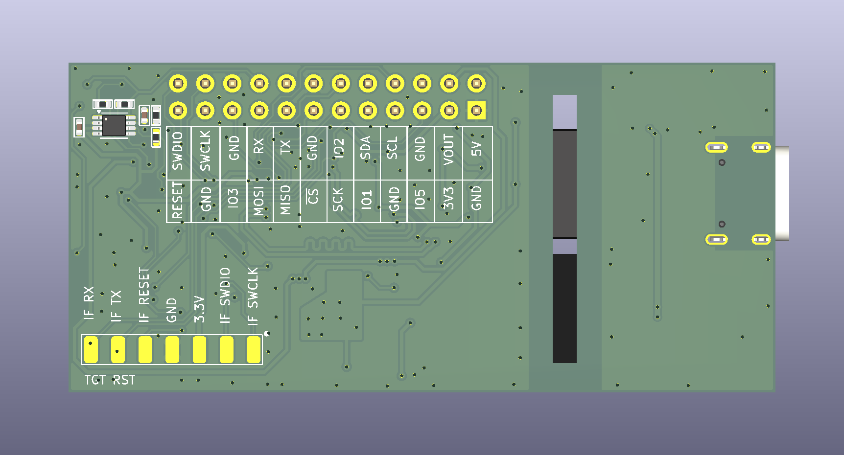
Bare SMD pads are provided to program the STM32 over SWD directly (solder wires). Used mainly to recover a blank part or one without a USB bootloader. See First-time STM32 programming.
UniDAP ships in a standard configuration; several jumpers/footprints let you reconfigure it.
| Ref | Default | Function |
|---|---|---|
| R501 | Populated | Routes CH347 GPIO1 to the ideal-diode gate, so GPIO1 controls the gated power output (standard config). |
| R502 | Unpopulated | Alternate route for CH347 GPIO1 to the main output header as a plain GPIO. Populate R502 and remove R501 to expose GPIO1 on the header instead of driving the gated output. |
| U502 | Unpopulated | Optional UART level shifter, supplied from the target voltage. |
| R505 / R507 | Populated | Direct (unshifted) connection of the DAPLink UART to the output header. Remove R505/R507 and populate U502 to route the UART through the level shifter. |
Gated power output: by default the isolated power to the target passes through an ideal-diode switch enabled by CH347 GPIO1, so power to the target can be switched under software control.
Level-shifted UART: in the standard configuration the DAPLink UART goes straight to the output header. Populating U502 (and removing R505/R507) shifts the UART to the target's logic level, referenced to the target supply.
The probe runs DAPLink (main branch).
0080The STM32 can be programmed for the first time (or recovered when no USB bootloader is present) two ways:
| Qty | Value | Footprint | References |
|---|---|---|---|
| 27 | 100nF | Reutronix_capacitors_SMD:C_0402 | C302, C305, C307, C309, C311, C312, C313, C314, C323, C325, C326, C327, C328, C330, C331, C332 +11 |
| 13 | 10k | Reutronix_resistor_SMD:R_0402 | R303, R310, R311, R312, R313, R322, R323, R409, R415, R416, R418, R419, R420 |
| 12 | 0R | Reutronix_resistor_SMD:R_0402 | R308, R317, R402, R414, R417, R501, R502, R503, R504, R505, R506, R507 |
| 12 | ESD5V0B03-1006 | Reutronix_diodes_SMD:DFN1006-2_SMD0402 | D402, D403, D404, D405, D406, D407, D501, D502, D503, D504, D505, D506 |
| 9 | 10uF | Reutronix_capacitors_SMD:C_0603 | C303, C304, C306, C308, C310, C320, C324, C401, C501 |
| 7 | 22R | Reutronix_resistor_SMD:R_0402 | R318, R319, R320, R321, R410, R411, R412 |
| 4 | 1.5k | Reutronix_resistor_SMD:R_0402 | R401, R403, R404, R413 |
| 4 | 18pF | Reutronix_capacitors_SMD:C_0402 | C407, C408, C411, C412 |
| 4 | 4.7uF | Reutronix_capacitors_SMD:C_0402 | C315, C316, C322, C329 |
| 3 | 100k | Reutronix_resistor_SMD:R_0402 | R301, R304, R314 |
| 3 | 4.7k | Reutronix_resistor_SMD:R_0402 | R324, R407, R408 |
| 3 | TAC_SW_4P_6mm | Reutronix_Switches:TS_6x6mm | SW401, SW402, SW403 |
| 2 | 10pF | Reutronix_capacitors_SMD:C_0402 | C318, C319 |
| 2 | 120R@100MHz | Inductor_SMD:L_0805_2012Metric | L302, L303 |
| 2 | 1uF | Reutronix_capacitors_SMD:C_0402 | C321, C406 |
| 2 | 22pF | Reutronix_capacitors_SMD:C_0402 | C333, C334 |
| 2 | 33R | Reutronix_resistor_SMD:R_0402 | R405, R406 |
| 2 | 5.1k | Reutronix_resistor_SMD:R_0402 | R306, R307 |
| 2 | 8MHz | Crystal:Crystal_SMD_2520-4Pin_2.5x2.0mm | Y302, Y402 |
| 2 | 9pF | Reutronix_capacitors_SMD:C_0402 | C409, C410 |
| 2 | DMG3415UFY4Q | Reutronix_packages_DFN_QFN:DMG3415UFY4Q-7 | Q501, Q502 |
| 2 | MBR1020VL | Diode_SMD:D_SOD-123F | D302, D303 |
| 1 | 100pF | Reutronix_capacitors_SMD:C_0402 | C317 |
| 1 | 10M | Reutronix_resistor_SMD:R_0402 | R309 |
| 1 | 10nF | Reutronix_capacitors_SMD:C_0402 | C301 |
| 1 | 12MHz | Crystal:Crystal_SMD_2520-4Pin_2.5x2.0mm | Y301 |
| 1 | 2.2uH | Inductor_SMD:L_1008_2520Metric | L301 |
| 1 | 32.768kHz | Crystal:Crystal_SMD_3215-2Pin_3.2x1.5mm | Y401 |
| 1 | 453k | Reutronix_resistor_SMD:R_0402 | R302 |
| 1 | 47.5k | Reutronix_resistor_SMD:R_0402 | R316 |
| 1 | 649R | Reutronix_resistor_SMD:R_0402 | R315 |
| 1 | 750315240 | Reutronix_magnetics:750315240 | TR301 |
| 1 | ADUM4160 | Package_SO:SOIC-16W_7.5x10.3mm_P1.27mm | U306 |
| 1 | CH347F | Package_DFN_QFN:QFN-28-1EP_4x4mm_P0.4mm_EP2.3x2.3mm | U307 |
| 1 | CY7C65634 | Package_DFN_QFN:QFN-28-1EP_5x5mm_P0.5mm_EP3.35x3.35mm | U304 |
| 1 | Conn_02x12_Odd_Even | Connector_PinHeader_2.54mm:PinHeader_2x12_P2.54mm_Vertical | J502 |
| 1 | Conn_ARM_JTAG_SWD_10 | Reutronix_connectors:SAMTEC_FTSH-105-XX-X-DV | J501 |
| 1 | LED_GREEN | Reutronix_diodes_SMD:LED_0402 | D401 |
| 1 | LED_RED | Reutronix_diodes_SMD:LED_0402 | D301 |
| 1 | PCB | NBT_PCB_stackup:4layer_ENIG_GREEN_JLC7628 | PCB101 |
| 1 | PRG | Reutronix_connectors:PROG_HEADER_SMD | J401 |
| 1 | SN6505ADBV | Package_TO_SOT_SMD:SOT-23-6 | U305 |
| 1 | SS8550 | Package_TO_SOT_SMD:SOT-323_SC-70 | Q401 |
| 1 | STM32F103CBTx | Package_QFP:LQFP-48_7x7mm_P0.5mm | U401 |
| 1 | TPS62A02A | Package_TO_SOT_SMD:SOT-563 | U302 |
| 1 | TXB0102DCU | Package_SO:VSSOP-8_2.3x2mm_P0.5mm | U502 |
| 1 | USBLC6-2P6 | Package_TO_SOT_SMD:SOT-666 | U303 |
| 1 | USB_C_Receptacle_USB2.0_16PIN | Connector_USB:USB_C_Receptacle_GCT_USB4105-xx-A_16P_TopMnt_Horizontal | J301 |
| 1 | XC8111AA018R-G | Reutronix_packages_USP:USP-6B06 | U501 |
| 1 | ТРАР22811AW5 | Package_TO_SOT_SMD:SOT-23-5 | U301 |
nonameCCC/PHASE-1
A compact modularized audio DAC & Headphone Amplifier.

El-Luhb/nvme-Carrier-for-LattePanda-Mu
nvme Carrier PCB for the LattePanda Mu compute module


dcuccia/digital-handbell
A software and hardware project to create a digital handbell using microcontrollers and speakers and gesture recognition

oomlout/oomlout_oomp_project_bot_v_2


neuroidss/FreeEEG32-beta
as FreeEEG32 plus alpha1.5 test passed, FreeEEG32 project changed to beta version

neuroidss/FreeEEG32-alpha1.0
ALPHA1.0 TEST FAILED, USE NEW VERSION INSTEAD FreeEEG32 alpha1.0 32 channels mobile electroencephalography under GNU AGPL 24 bits, 4kSPS ADCs 4x AD7770 MCU STM32F427ZI WIFI ESP-12F (ESP8266) USB CP2102N Accel & hyro…
It measures 66.2 × 30.9 mm and has 4 copper layers, 2.03 mm thick.
149 parts, built around the CH347F, SN6505ADBV, TPS62A02ADRL and ADUM4160BRW. The full list of its parts is on this page, with links to each part's symbol and footprint where PCBKit's library has them.
From the Reutronix/uni-dap-v3 repository on GitHub, at the commit this page was made from: the board is uni-dap.kicad_pcb and its schematic dap-link.kicad_sch. PCBKit opens the board in the browser, with nothing to install.
Its repository states no licence, so its author keeps all rights: ask Reutronix before reusing the design.