2 layers18.5 × 26 mm
24g2usb rp2350zero
joypad-ai/joypad-os
Universal controller firmware for building adapters, dongles, and custom controllers.
4 parts1.7kApache-2.0
 RetroStack/TRS-80-USB-Keyboard10
A USB keyboard adapter for original TRS-80 keyboards
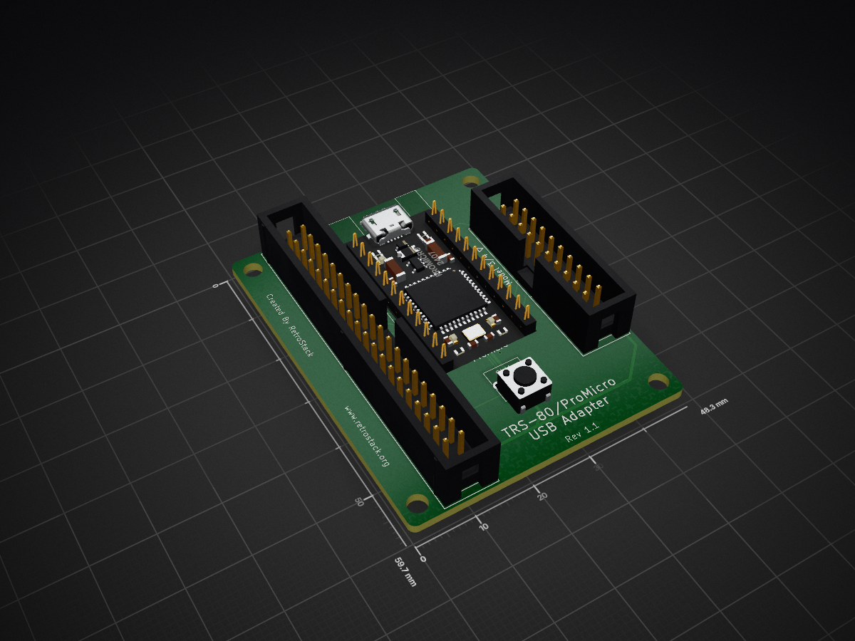
TRS80 USB Keyboard ProMicro Adapter is an open-source printed circuit board by RetroStack, from the RetroStack/TRS-80-USB-Keyboard repository on GitHub, published under the MIT licence. It is a 2-layer board of 48.3 × 59.7 mm with 4 parts on 25 nets, routed with 229 tracks and 6 vias.
Its parts include 2 connectors, 1 IC and 1 switch. It belongs with the keyboards and input and interfaces and adapters boards and the AVR (ATmega, ATtiny) boards of this library.
This project enables the connection of an original TRS-80 keyboard to a modern computer via USB. It supports multiple TRS-80 models and various development boards for interfacing the keyboard with a system over USB. The entire project is available under the MIT license.
NOTE: I was made aware of a great project which does the reverse of this for multiple systems. Check out the following repo if you need that: https://github.com/ITDiscovery/AVR128PS2Keyboard
TRS-80 keyboards typically expose the keyboard matrix directly at the connector, revealing the rows and columns of this matrix and allowing the CPU to handle all decoding. This capability enables us to connect these keyboards directly to Arduino I/O ports and utilize the onboard USB controller to function as a human interface device (HID).
The following TRS-80 models are currently supported:
Several Arduino development boards can be used for this project, but the code was specifically confirmed on the following boards (prices as of April 2024):
NOTE: Since the TRS-80 generally uses +5V, ensure that the boards are 5V compatible. For example, the ItsyBitsy and Pro Micro boards also have 3.3V variants.
All code is located in the "TRS80USBKeyboard" folder.
To connect a specific keyboard model to a development board, select a model in the config.h file in the root of the code directory "TRS80USBKeyboard". For more details, refer to the "Configuration" -> "Model" section below.
Each model has a specific pinout. Connect a wire to each of the pins listed below:
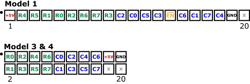
NOTE: Some schematics define ROWS and COLUMNS oppositely. Because a matrix can be seen from either perspective (transposed), I've used the same matrix structure for consistency with Model 1. Refer to this pinout to avoid receiving garbage and erratic keyboard behavior.
The pins marked as "X" are unconnected. You don't need to attach a wire there. All keyboards have a "+5V" and "GND" pin that need to be connected to the appropriate pins on the development board. See the "Connect a Board" section below.
For the Model 1, there is also the "EN" signal. This model has active logic components on the board. To activate them, this signal must be connected to GND.
NOTE: Some boards provide a KEYBOARD_ENABLED_PIN option to pull this pin down. However, you can also always activate it by connecting it to GND.
Now, with one side of all the wires connected, let's examine the board.
To connect a specific development board, select one board in the config.h file in the root of the code directory "TRS80USBKeyboard". For more details, refer to the "Configuration" -> "Boards & Custom Board" section below.
Each board has its own pinout. Use the code as a reference by opening the selected board from the boards directory.
There is an adapter board for the Pro Micro that will help with connecting the pins. See "Adapter Board" below.
Within each file, there are definitions for the row and column pins. An example would look as follows:
#define R0_PIN 12This indicates that the R0 signal from the keyboard model above needs to be connected to pin 12 of the development board. Connect all columns and rows to the corresponding pins on the development board.
Also, connect the "+5V" and "GND" pins to the corresponding pins on each board. These pins are usually marked as such.
If you have the "EN" signal from the keyboard (in case you selected the Model 1), connect it to another GND pin on the development board or use the KEYBOARD_ENABLED_PIN defined in the config (if it differs from 0).
The code offers several options for configuring the program that will be executed.
Upon opening the project, you will see a "config.h" file. Open it, and let's explore the configuration options.
Each option in this file is defined with a #define. This informs the compiler about the features you want to include in the compiled binary. You can deactivate an option by adding // in front of it. Removing it activates the feature.
DEBUGWhen active, this option disables the USB functionality. Instead of sending keypresses and releases over USB, it uses the serial interface to send textual information about each key press and release in ASCII, decimal, and binary format. This is useful for debugging your setup to ensure it functions as expected.
NOTE: This option respects the ECHO_ENABLED_PIN.
NOTE: This option allows testing on development boards that do not support USB HID functionality, such as the Arduino Mega.
USB_KEYBOARDWhen active, the USB interface is used to send keypresses and releases. Upon startup, the development board will identify itself to the host system as a keyboard.
When deactivated, it uses the serial interface to send keypresses only. This may be beneficial for connecting the keyboard to a custom non-USB host system.
SERIAL_BAUD_RATEThis option is followed by a value representing the number of signal changes per second. 9600 is a common default, as it is sufficiently fast for a keyboard and supported by many boards. If unsure, leave this option as is.
REPEAT_DELAY_MSThis option emulates the AT repeat rate in milliseconds for TRS-80 keyboards. By default this is set to 0 to deactivate. A reasonable value is 250 ms.
There is a list of various models supported with a Model# pattern. Choose only one option. Selecting multiple will cause compilation errors.
There is a list of various boards that are supported. Choose only one option. Selecting multiple will also lead to compilation errors.
There is also an additional option called Arduino_Custom which allows for the inclusion of unsupported development boards. See the "Define Custom Board" section below for details.
Each board requires specific drivers and/or boards to be installed. Please refer to the linked product pages above and their relevant documentation. For the generic Pro Micro, you can use the instructions for the Sparkfun Pro Micro.
Each board, when sufficient pins are available, has a ECHO_ENABLED_PIN defined. This feature disables sending keyboard press and release data over the USB cable, which might interfere with the upload of new binaries. To disable the keyboard data, connect this pin to GND. Without a connection, by default, the pin is active.
Make your selections for the model and board in the config. Then, click "Upload" in the Arduino IDE to compile and upload the binary to your development board.
NOTE: If you encounter errors, you might have selected multiple models or boards, or none at all. Ensure that at most one is selected for each type.
When the binary is uploaded, a dialog from the operating system might appear as it recognizes the development board as a new keyboard. Feel free to close it.
To test it, ideally, open a text editor and try out all keys. If an LED is available on your development board (often pin 13 or 6), then each keypress should be recognized, and the LED will flash.
If you do not have one of the pre-configured development boards, you can define your own. The file arduino_custom_config.h is provided for this purpose. Activate this option in the config.h file and open the arduino_custom_config.h file.
There, you have the following options:
ECHO_ENABLED_PINThe ECHO_ENABLED_PIN is by default pulled high. When pulled down (for example, when connected to GND), the USB keyboard functionality is deactivated. This feature is useful when keypresses interfere with binary uploads.
KEYPRESS_LED_PINThis pin is used as an indicator LED when a keypress is recognized. For each keypress, this LED flashes. You can deactivate this feature by specifying the pin as "0".
KEYBOARD_ENABLED_PINThis is an optional pin that might be used by some specific keyboard models. However, you should also be able to set the keyboard signal to GND and skip this pin altogether. When set to "0", this feature is ignored. Otherwise, it simply sets this pin to GND when the keyboard is accessed.
R#_PIN and C#_PINThese definitions select the individual pins for each keyboard signal.
For your convenience, an adapter board has been added to this repository, as creating a ribbon cable for all the pins can be quite cumbersome. You can find it in the Adapters folder.
Below is a photo of a fully assembled adapter board with a Pro Micro pre-installed:
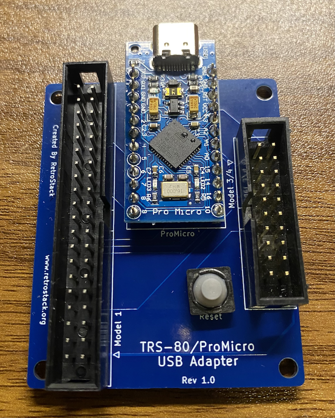
This adapter board allows the TRS-80 Model 1, 3, and 4 to connect to the Pro Micro and the device to act as a USB Host.
A convenient RESET button is included for resetting the Pro Micro, especially useful if you’ve accidentally uploaded a 3.3V version.
Gerber files are available in the Latest folder:
For additional resources related to the TRS-80 Model 1, be sure to check out the central page for the TRS-80 Model 1 on RetroStack. You can find it here.
RetroStack is passionate about exploring and preserving the legacy of older computer systems. My work involves creating detailed documentation and videos to share the knowledge. I am also dedicated to reviving these classic systems by reimplementing them and offering replacement parts at no cost. If you're keen on supporting this unique project, I invite you to visit my Patreon page. Your support would be immensely valuable and greatly appreciated!
This project is licensed under the MIT License - see the LICENSE file for details.
| Qty | Value | Footprint | References |
|---|---|---|---|
| 1 | Model 1 | Connector_IDC:IDC-Header_2x20_P2.54mm_Vertical | J1 |
| 1 | Model 3/4 | Connector_IDC:IDC-Header_2x10_P2.54mm_Vertical | J2 |
| 1 | ProMicro | RetroStackLibrary:ProMicro | U1 |
| 1 | SW_Reset | RetroStackLibrary:SW_SPST_Push | SW1 |
joypad-ai/joypad-os
Universal controller firmware for building adapters, dongles, and custom controllers.


hackclub/OnBoard
💡 Join 1,000 teenagers and make your first PCB with a $100 grant!

tardate/LittleArduinoProjects
a collection of "Little Electronic & Arduino Projects", most involving electronics or an Arduino in one way or another!

drandyhaas/KiCadRoutingTools
A set of Python/Rust tools to aid routing in KiCad

osy/XG_Mobile_Station
Open source eGPU dock for ROG Ally and ROG Flow

Luos-io/luos_engine
Open-source and real-time orchestrator for cyber-physical-systems, to easily design, test and deploy embedded applications and digital twins.

NVNTLabs/switch2-SDEX2M2
Micro SD Express to M.2 NVME Adapter for Nintendo Switch 2
It measures 48.3 × 59.7 mm and has 2 copper layers, 1.6 mm thick.
4 parts. The full list of its parts is on this page, with links to each part's symbol and footprint where PCBKit's library has them.
From the RetroStack/TRS-80-USB-Keyboard repository on GitHub, at the commit this page was made from: the board is Adapters/TRS80_USB_Keyboard_ProMicro_Adapter/TRS80_USB_Keyboard_ProMicro_Adapter.kicad_pcb and its schematic Adapters/TRS80_USB_Keyboard_ProMicro_Adapter/TRS80_USB_Keyboard_ProMicro_Adapter.kicad_sch. PCBKit opens the board in the browser, with nothing to install.
Its repository publishes it under the MIT licence: you may reuse it on that licence's terms (keep the author's notice, and for a copyleft licence share your changes alike).