
2 layers60 × 30 mm
Controller
google/mozc-devices
Circuit diagrams and firmware source code for Gboard DIY keyboards
11 parts3kApache-2.0

A Simple Hardware Mod to Fix Cassette Loading in Earlier Versions of the TRS-80 Model 1
XRX Mod is an open-source printed circuit board by RetroStack, from the RetroStack/TRS-80-Model-I-XRX-III repository on GitHub, published under the MIT licence. It is a 2-layer board of 37.7 × 29.7 mm with 11 parts on 22 nets, routed with 75 tracks and 0 vias.
Its parts include 6 connectors and 1 resistor.
This project faithfully reimplements the small brown mod board often seen attached to the keyboard of an TRS-80 Model 1. It corrects a software bug in earlier versions of the Level II ROMs, a bug later fixed in version 1.3. The design replicates the original mod's functionality using a 1-to-1 PCB design, including components, interfaces, and even traces.
Since this mod is no longer required for the latest ROM version, there's no need to create it. If you have an older computer, simply update the ROMs, and this mod becomes unnecessary. This repository serves more as a historical record and recreation of the board rather than for implementation.
For more details about this mod, visit: http://www.trs-80.org/xrx-modification/
The entire project is available under the MIT license.
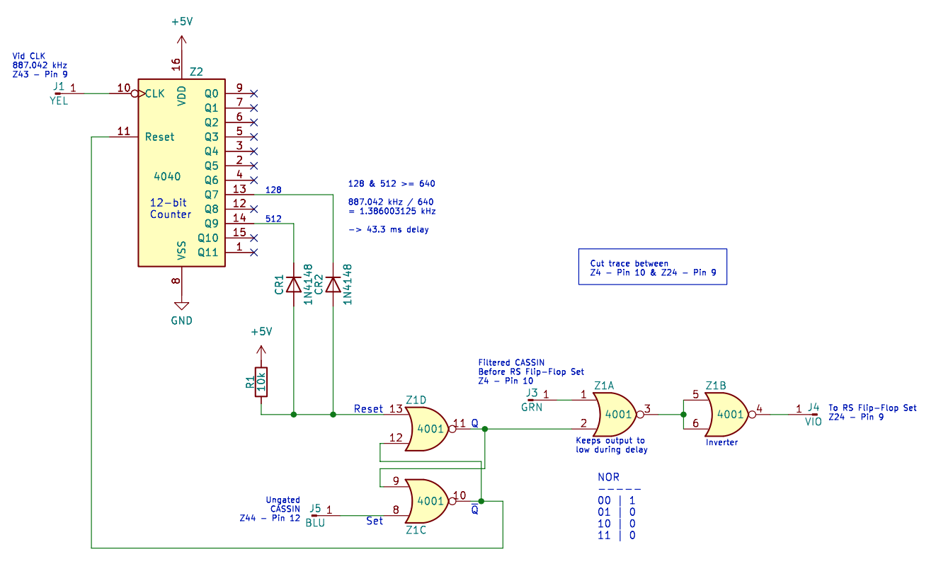
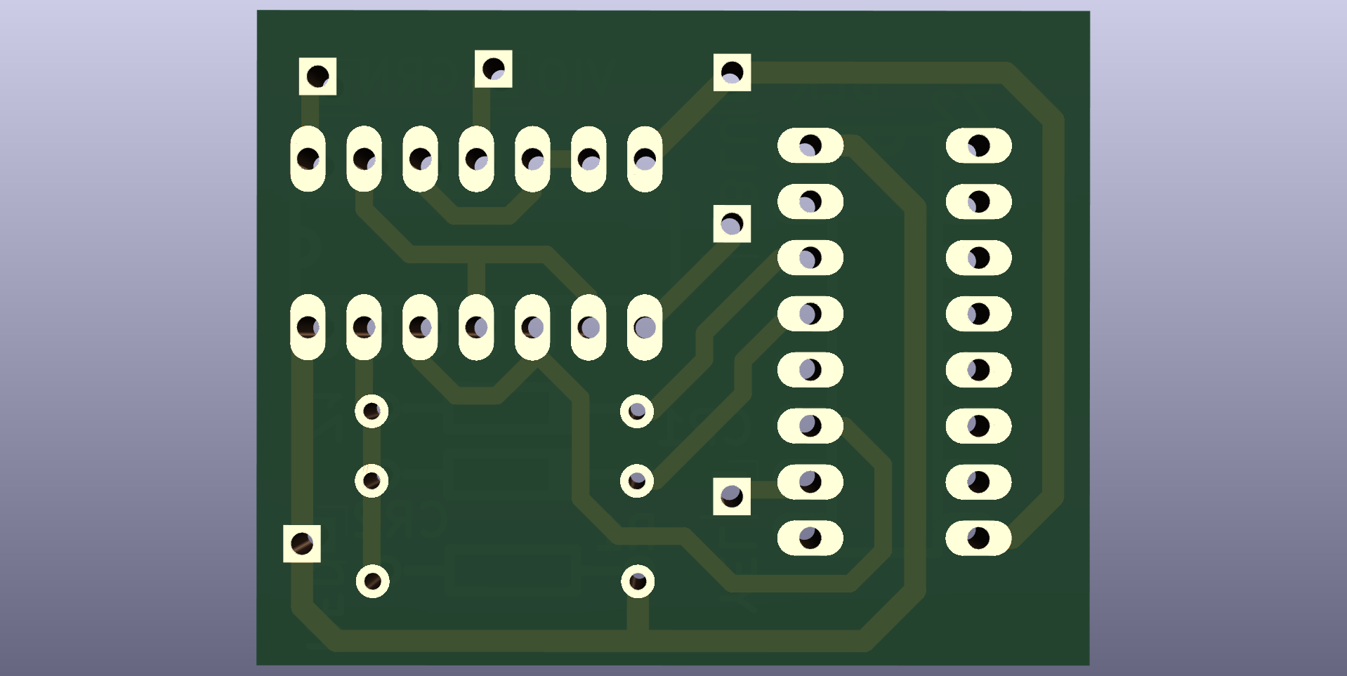
In the "Latest" folder, you'll find the most up-to-date design files, including:
This board has been implemented using KiCAD 7. The KiCAD project files are included in this repository.
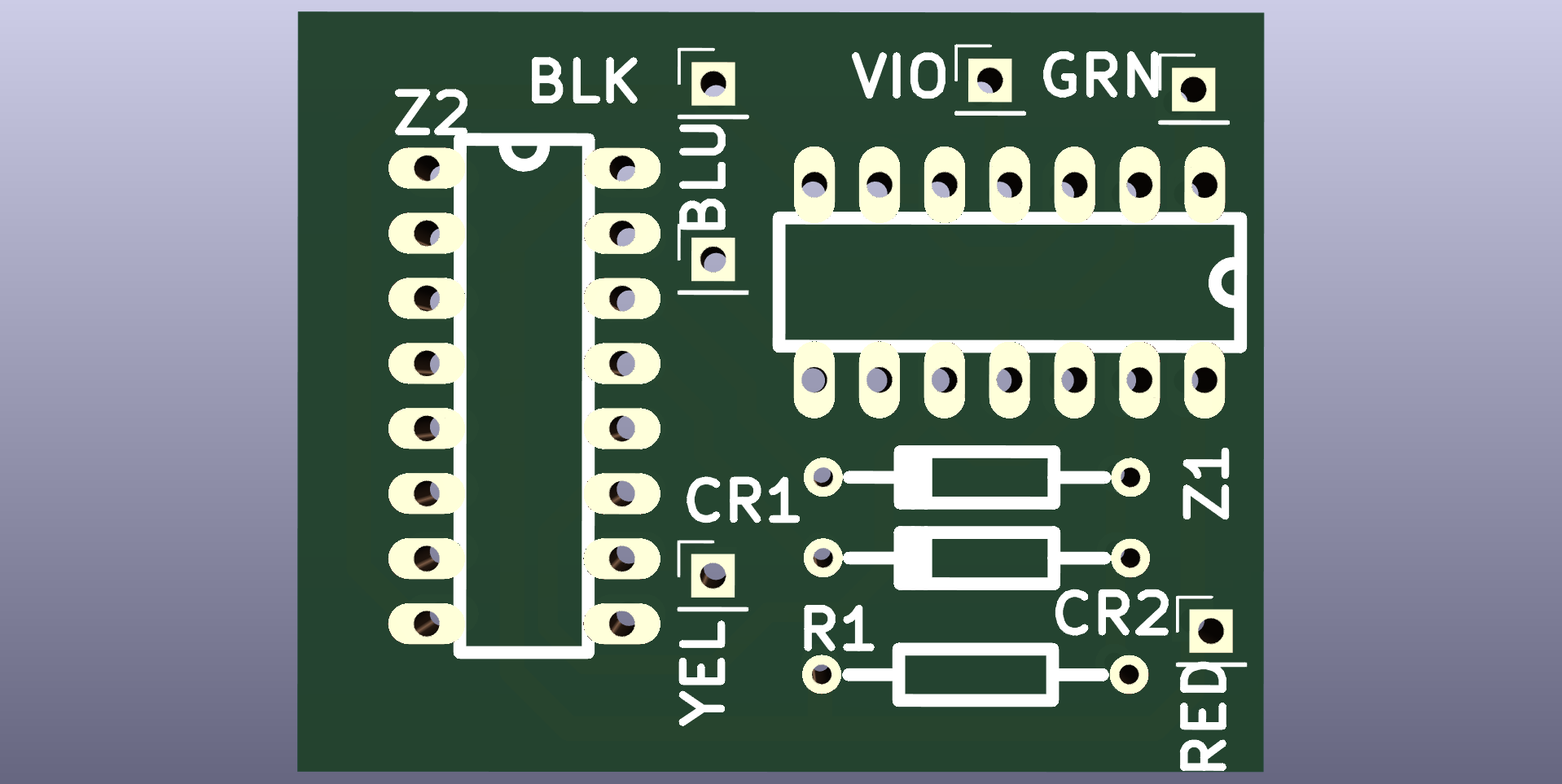
The mod monitors when the cassette-interface-in flip-flop on the main board resets. Upon this event, it performs two actions:
The counter, utilizing a clock from the video circuitry, counts until 43.3ms have elapsed, after which it resets the mod flip-flop and reopens the cassette data-in port. This process helps to avoid noise being accidentally picked up by the software, which was listening too early (a bug in early system ROM versions).
The board employs two NOR gates for the flip-flop and uses the other two NOR gates to gate the CASSIN signal and then to invert its value (since the gating also inverts the data, restoring the original state of CASSIN).
Another noteworthy aspect is the use of the two diodes and the pull-up resistor, configured to function like an AND gate. Opting for diodes and a resistor was likely a more cost-effective solution than adding another IC.
To work with this KiCAD project, you'll need the RetroStack libraries for KiCAD. Please follow this link to access and install these libraries.
For additional resources related to the TRS-80 Model 1, be sure to check out the central page for the TRS-80 Model 1 on RetroStack.
RetroStack is dedicated to learning about older computer systems and creating documentation and videos about them. We are also resurrecting older computer systems by reimplementing them and making replacement parts available for free. If you're interested in supporting this project, consider visiting our Patreon page. Your support is greatly appreciated!
This project is licensed under the MIT License - see the LICENSE file for details.
| Qty | Value | Footprint | References |
|---|---|---|---|
| 2 | 1N4148 | RetroStackLibrary:TRS80_Model_I_D | CR1, CR2 |
| 1 | 10k | RetroStackLibrary:TRS80_Model_I_R_0.25W | R1 |
| 1 | 4001 | RetroStackLibrary:TRS80_Model_I_DIP14 | Z1 |
| 1 | 4040 | RetroStackLibrary:TRS80_Model_I_DIP16 | Z2 |
| 1 | BLK | Connector_PinHeader_2.54mm:PinHeader_1x01_P2.54mm_Vertical | J6 |
| 1 | BLU | Connector_PinHeader_2.54mm:PinHeader_1x01_P2.54mm_Vertical | J5 |
| 1 | GRN | Connector_PinHeader_2.54mm:PinHeader_1x01_P2.54mm_Vertical | J3 |
| 1 | RED | Connector_PinHeader_2.54mm:PinHeader_1x01_P2.54mm_Vertical | J2 |
| 1 | VIO | Connector_PinHeader_2.54mm:PinHeader_1x01_P2.54mm_Vertical | J4 |
| 1 | YEL | Connector_PinHeader_2.54mm:PinHeader_1x01_P2.54mm_Vertical | J1 |
google/mozc-devices
Circuit diagrams and firmware source code for Gboard DIY keyboards


FrameworkComputer/ExpansionCards
Reference designs and documentation to create Expansion Cards for the Framework Laptop

hoglet67/RGBtoHDMI
Bare-metal Raspberry Pi project that provides pixel-perfect sampling of Retro Computer RGB/YUV video and conversion to HDMI

hackclub/OnBoard
💡 Join 1,000 teenagers and make your first PCB with a $100 grant!


tardate/LittleArduinoProjects
a collection of "Little Electronic & Arduino Projects", most involving electronics or an Arduino in one way or another!

basilfx/TRADFRI-Hacking
Hacking IKEA TRÅDFRI products, such as light bulbs, window blinds and other accessories.
It measures 37.7 × 29.7 mm and has 2 copper layers, 1.6 mm thick.
11 parts. The full list of its parts is on this page, with links to each part's symbol and footprint where PCBKit's library has them.
From the RetroStack/TRS-80-Model-I-XRX-III repository on GitHub, at the commit this page was made from: the board is KiCAD/XRX_Mod.kicad_pcb and its schematic KiCAD/XRX_Mod.kicad_sch. PCBKit opens the board in the browser, with nothing to install.
Its repository publishes it under the MIT licence: you may reuse it on that licence's terms (keep the author's notice, and for a copyleft licence share your changes alike).