2 layers18.5 × 26 mm
24g2usb rp2350zero
joypad-ai/joypad-os
Universal controller firmware for building adapters, dongles, and custom controllers.
4 parts1.7kApache-2.0

 RetroStack/TRS-80-Model-I-Power-Supply4
A power supply for the TRS-80 Model I
TRS-80-Model I Power Supply is an open-source printed circuit board by RetroStack, from the RetroStack/TRS-80-Model-I-Power-Supply repository on GitHub, published under the MIT licence. It is a 2-layer board of 19.9 × 19.9 mm with 4 parts on 6 nets, routed with 28 tracks and 0 vias.
Its parts include 2 diodes and 2 connectors. It belongs with the power boards of this library.
DEPRECATED This repository is deprecated. Please refer to the new power supply repository.
This project is a reimplementation of the TRS-80 Model 1 Power Supply that replicates the DC and AC voltages needed to run the original system. This revision is based on the original design and uses some of the findings from www.shockrisk.com. The entire project is available under the MIT license.
NOTE: There is another power supply available by Matt Boytim that appears to be smaller and cheaper. Consider using that design.
WARNING: Since this project works with high voltages, please only do this if you know what you are doing. Working on high voltages can kill you! Additionally, doing things incorrectly could burn down your house.
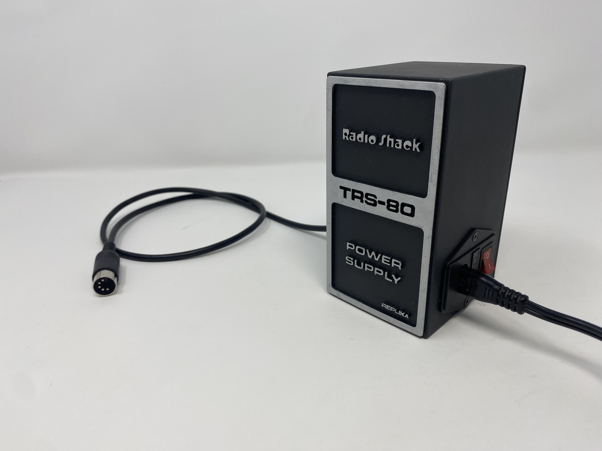
In the "Latest" folder, you'll find the most up-to-date design files, including:
Below is a list of materials needed to assemble a complete power supply. Please note that the links and prices (as of March 31st, 2024) will not be updated in the future and should only be used as a reference for locating the correct items.
Note: Links and alternatives are provided to assist you in finding the necessary components. I cannot guarantee the complete accuracy or reliability of all these links and alternatives. Please check it for yourself!
| Reference | Quantity | Value | Component Name | Description | Source Comment | Source Cost USD | Source Total Cost USD | Source |
|---|---|---|---|---|---|---|---|---|
| D1, D2 | 2 | 1N4001 | 50V 1A General Purpose Rectifier Diode, DO-41 | Rectifying diodes | $0.10 | $0.20 | Mouser | |
| F1 | 1 | ~ | 250V 1A Fast Blow 5x20mm | $0.36 | $0.36 | Mouser | ||
| T1 | 1 | F-241U | Transformer, single primary, dual secondary | $25.10 | $25.10 | Mouser | ||
| 1 | PCB | Lot of 5 | ~$0.40 | ~$0.40 | - | |||
| 8 | M3 3x5mm | Knurled Nut | Kit | ~$0.00 | ~$0.00 | Amazon | ||
| 2 | M3 4mm | Screw /w Sunk head,For Power unit | - | |||||
| 2 | M3 6mm | Screw | For PCB | - | ||||
| 4 | M3 8mm | Screw | For Lid | - | ||||
| 4 | M4 4x6mm | Knurled Nut | All 4 to hold transformer in place | Kit | ~$0.00 | ~$0.00 | Amazon | |
| 4 | M4 6mm | Screw | Transformer | - | ||||
| 6 | FDFD1.25-187 | Female Insulating Spade Connector | Cables for terminals of the power unit | Lot of 100 | ~$0.00 | ~$0.00 | AliExpress | |
| 1 | Power Unit | With switch and Fuse holder | $3.30 | $3.30 | AliExpress | |||
| 1 | Strain Relief | Cable Strain Relief | Lot of 10 | $0.68 | $0.68 | Amazon | ||
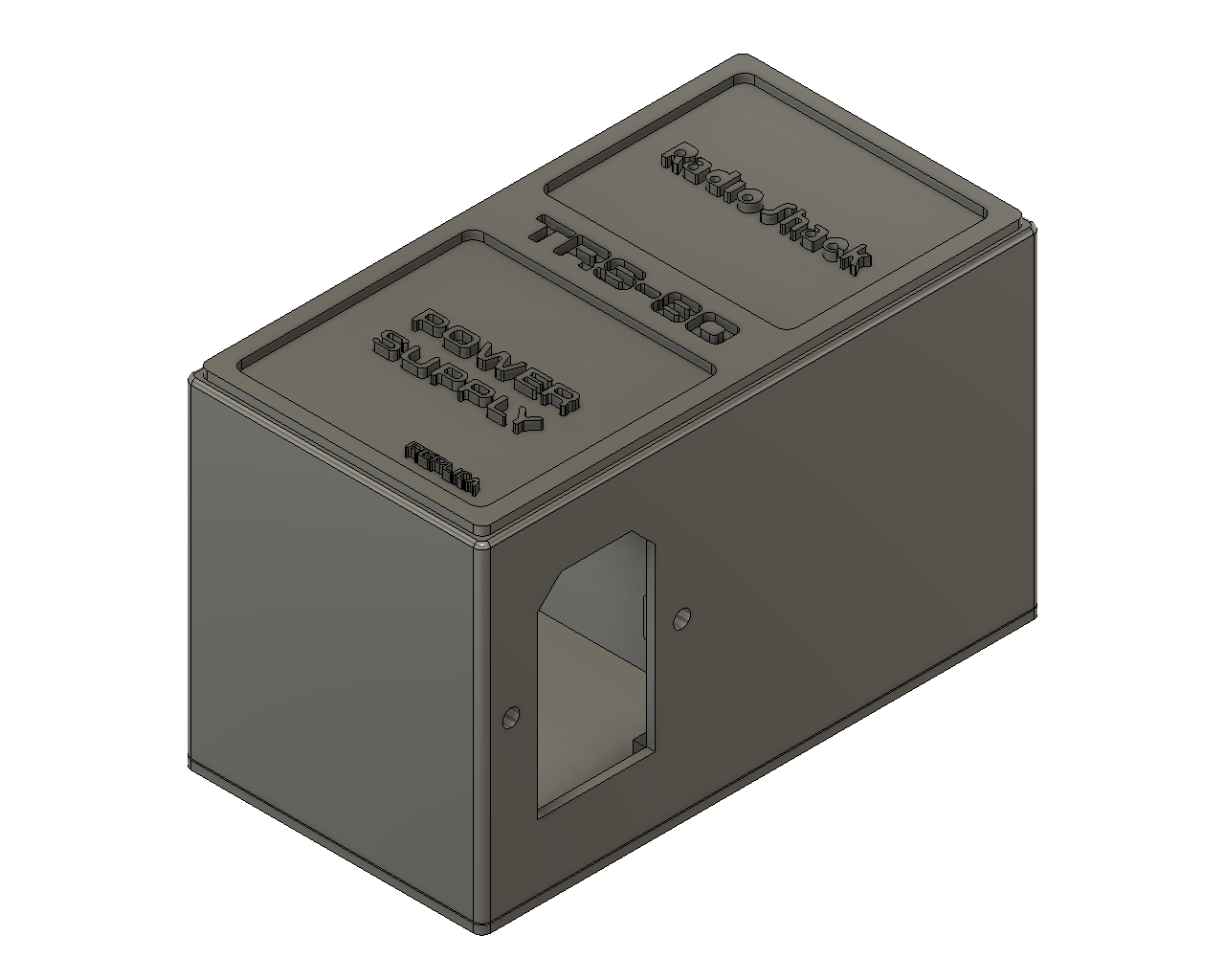
| 1 | Lid | 3D Printed | - | |||||
| 1 | Base | 3D Printed | - |
Prepare Case
Electronics
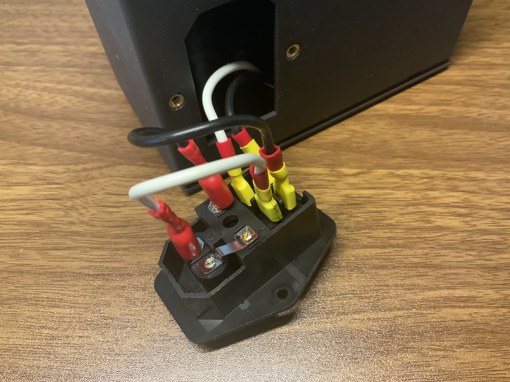
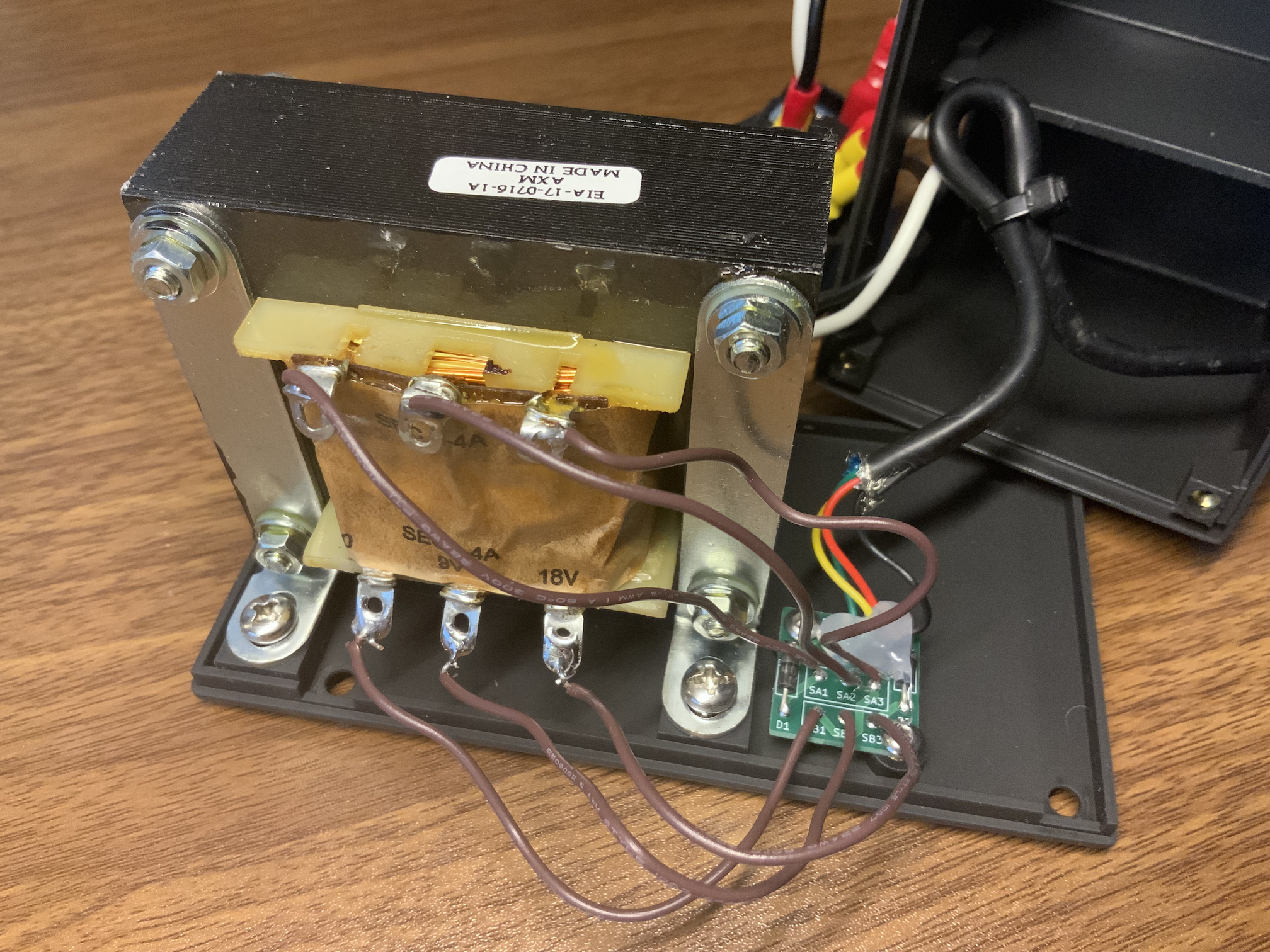
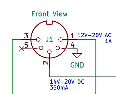
The project has been implemented using KiCAD 7. The KiCAD project files are included in this repository.
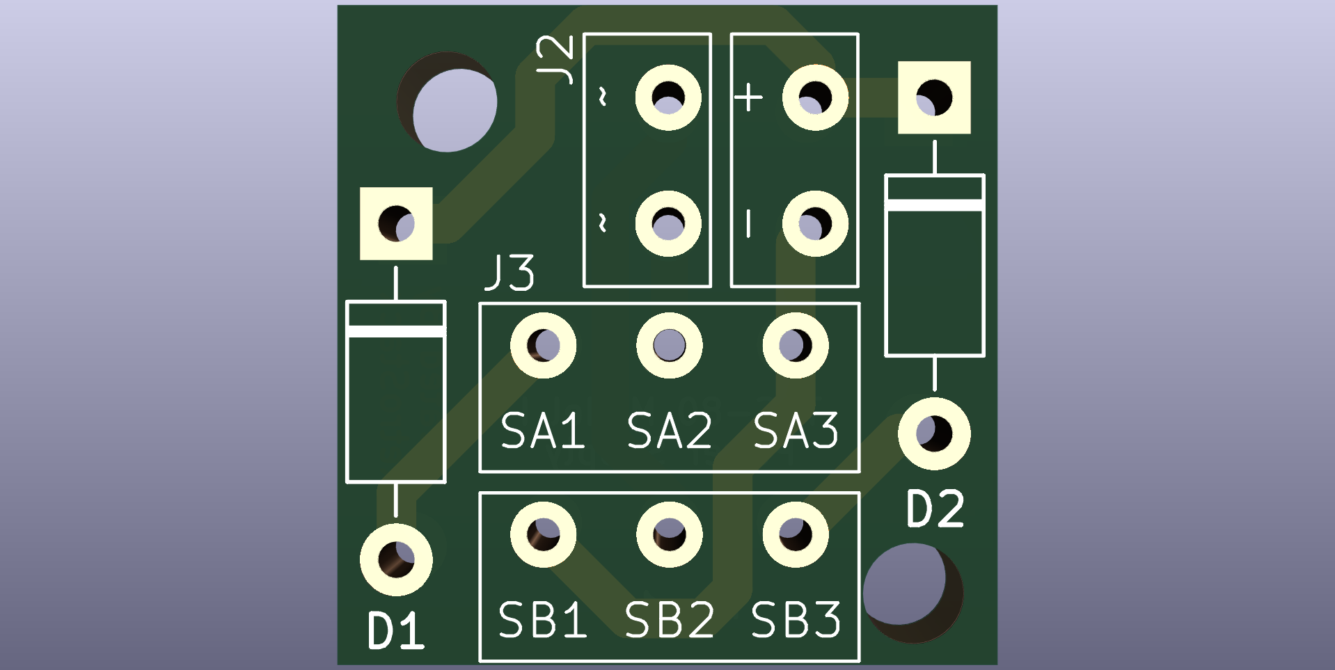
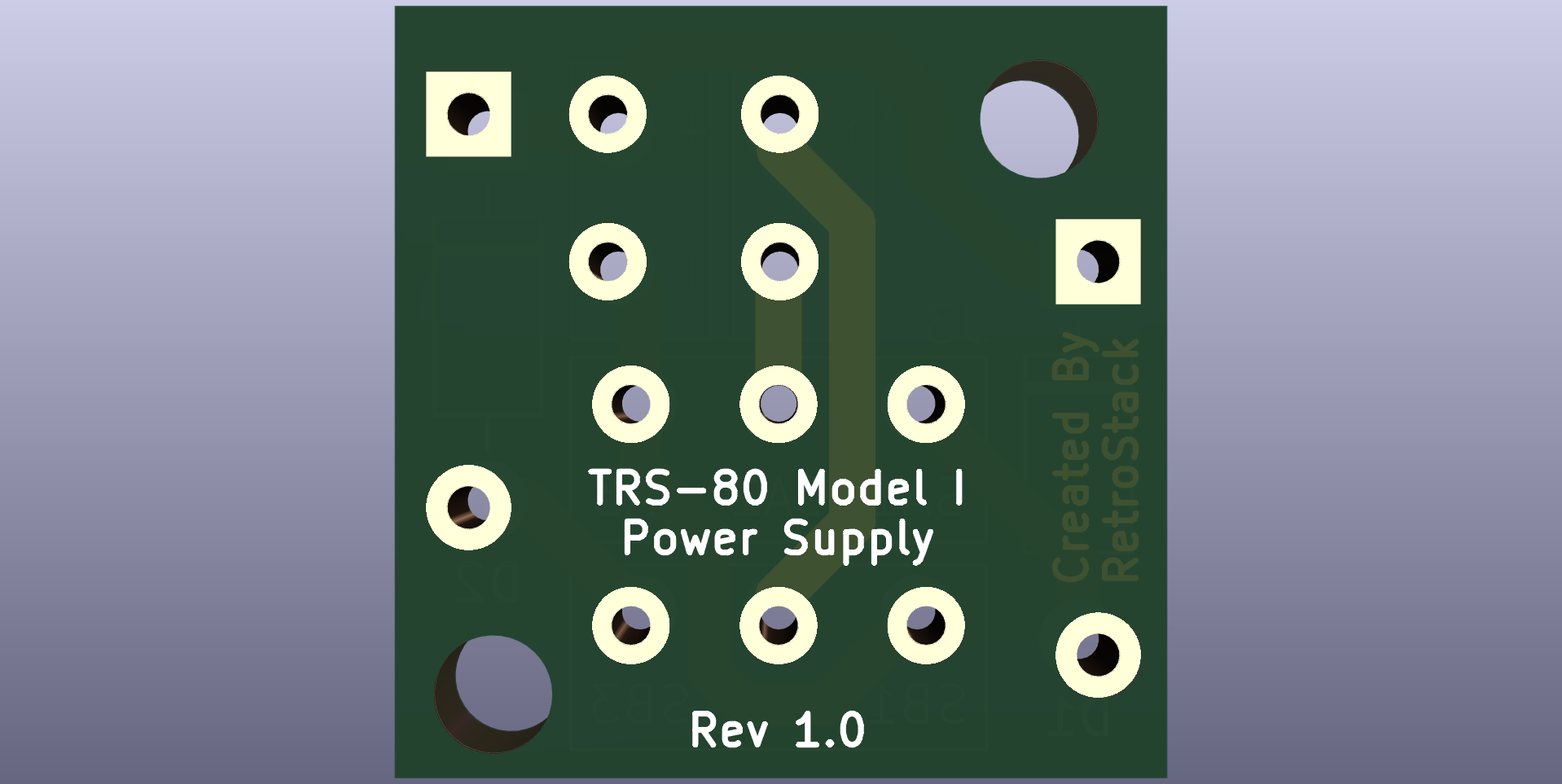
To work with this KiCAD project, you'll need the RetroStack libraries for KiCAD. Please follow this link to access and install these libraries.
For additional resources related to the TRS-80 Model 1, be sure to check out the central page for the TRS-80 Model 1 on RetroStack. You can find it here.
RetroStack is passionate about exploring and preserving the legacy of older computer systems. My work involves creating detailed documentation and videos to share the knowledge. I am also dedicated to reviving these classic systems by reimplementing them and offering replacement parts at no cost. If you're keen on supporting this unique project, I invite you to visit my Patreon page. Your support would be immensely valuable and greatly appreciated!
This project is licensed under the MIT License - see the LICENSE file for details.
| Qty | Value | Footprint | References |
|---|---|---|---|
| 2 | 1N4001 | Diode_THT:D_DO-41_SOD81_P10.16mm_Horizontal | D1, D2 |
| 1 | Conn_01x04 | RetroStackLibrary:TRS80_Model_I_PWR_Connector | J2 |
| 1 | Conn_01x06 | RetroStackLibrary:TRS80_Model_I_Transformer_Connector | J3 |
joypad-ai/joypad-os
Universal controller firmware for building adapters, dongles, and custom controllers.


hackclub/OnBoard
💡 Join 1,000 teenagers and make your first PCB with a $100 grant!

tardate/LittleArduinoProjects
a collection of "Little Electronic & Arduino Projects", most involving electronics or an Arduino in one way or another!

drandyhaas/KiCadRoutingTools
A set of Python/Rust tools to aid routing in KiCad

osy/XG_Mobile_Station
Open source eGPU dock for ROG Ally and ROG Flow

Luos-io/luos_engine
Open-source and real-time orchestrator for cyber-physical-systems, to easily design, test and deploy embedded applications and digital twins.

NVNTLabs/switch2-SDEX2M2
Micro SD Express to M.2 NVME Adapter for Nintendo Switch 2
It measures 19.9 × 19.9 mm and has 2 copper layers, 1.6 mm thick.
4 parts. The full list of its parts is on this page, with links to each part's symbol and footprint where PCBKit's library has them.
From the RetroStack/TRS-80-Model-I-Power-Supply repository on GitHub, at the commit this page was made from: the board is KiCAD/TRS80_Model_I_Power_Supply.kicad_pcb and its schematic KiCAD/TRS80_Model_I_Power_Supply.kicad_sch. PCBKit opens the board in the browser, with nothing to install.
Its repository publishes it under the MIT licence: you may reuse it on that licence's terms (keep the author's notice, and for a copyleft licence share your changes alike).