2 layers28.3 × 39.8 mm
LevelShifter
gusmanb/logicanalyzer
24 channel, 100Msps logic analyzer hardware and software
21 parts5.1kGPL-3.0

 RetroNynjah/IEC-Switch2
Switch for Commodore disk drives
IEC Switch is an open-source printed circuit board by RetroNynjah, from the RetroNynjah/IEC-Switch repository on GitHub, published under the GPL-3.0 licence. It is a 2-layer board of 198.1 × 95.3 mm with 21 parts on 77 nets, routed with 250 tracks and 0 vias.
Its parts include 8 connectors and 7 switches.
A switch for Commodore 8-bit computers that allows connection of six IEC disk devices (six cables) to two computers.
The chains can be switched on an off individually.
It doesn't allow more devices to be active at the same time but it allows devices to be connected and disconnected without touching any cables.
I.e. if you have three devices that are all using device number 8 you can activate one at a time using switches without disconnecting the other two.
The switch by the front input toggles connection between ccomputer on the rear input and a computer on the front input.
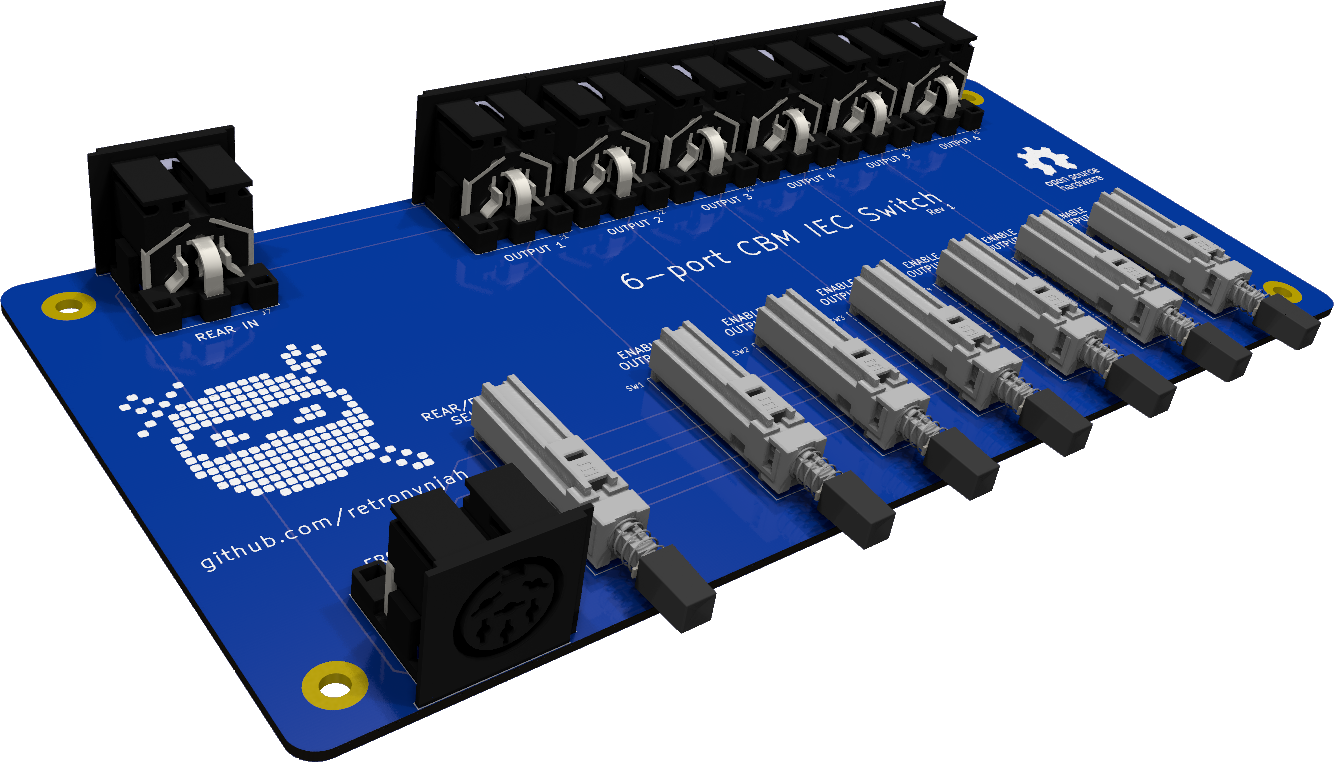
The only components on the PCB are eight female 6-pin DIN connectors and seven latching switches (E-Switch PBH6U). A suitable part is PBH6UEENAG1DBLK.
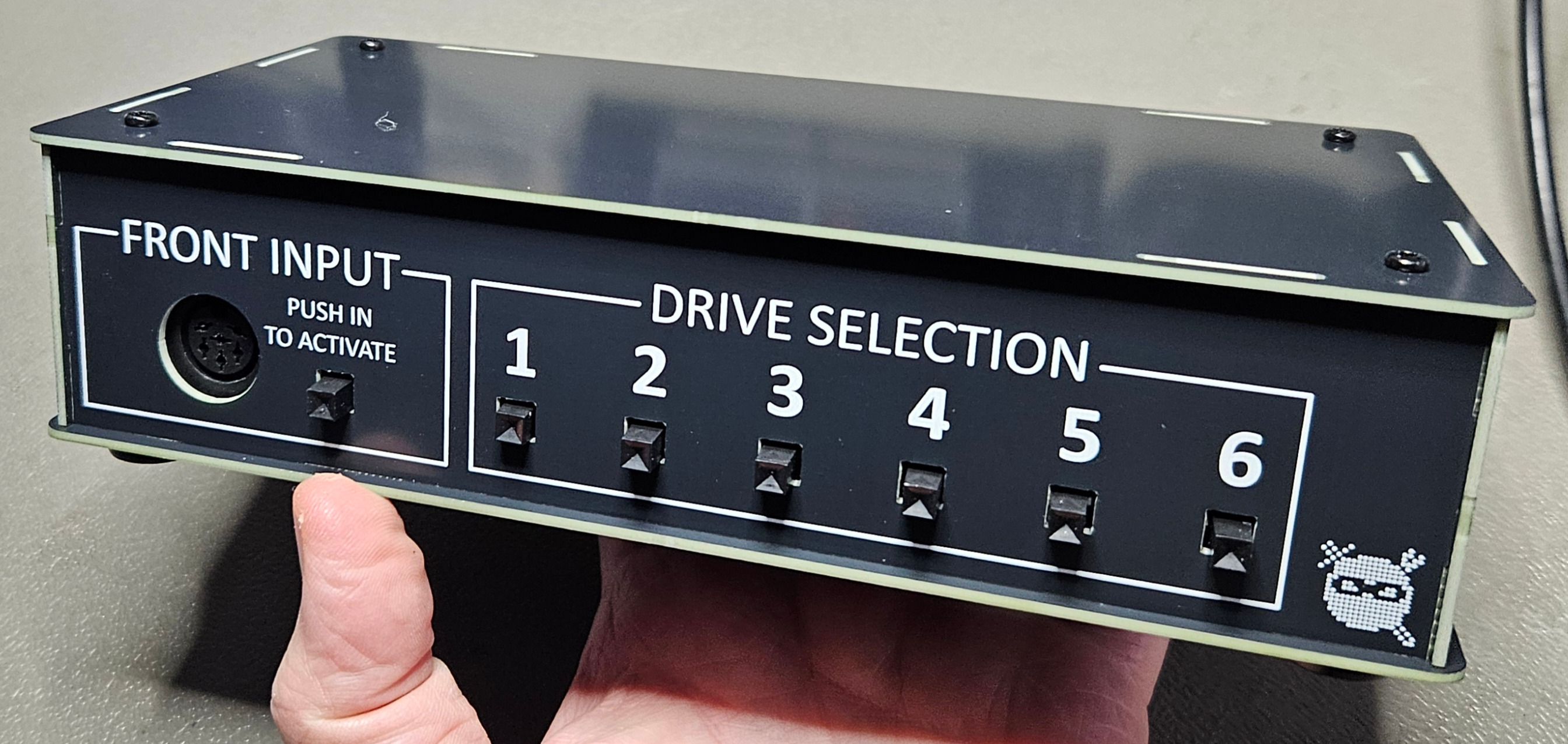
A suitable enclosure can be built using PCBs. All gerbers are included in this repository.
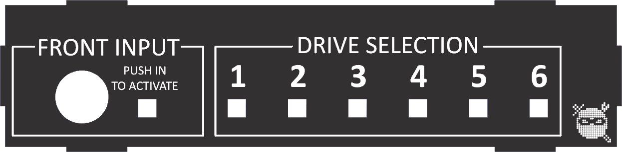


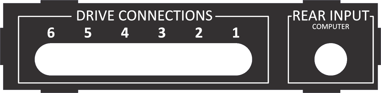
| Part | Qty | Comments |
|---|---|---|
| Top/Bottom PCB | 2 | |
| Side PCB | 2 | |
| Front PCB | 1 | |
| Back PCB | 1 | |
| Stand-off | 4 | M3 40 mm female-female, brass or plastic |
| Stand-off | 4 | M3 5 mm male-female, brass or plastic |
| Rubber feet | 4 | With screw mounts suitable for M3 screws |
| Screw | 8 | M3 7 mm. For bottom feet and top |
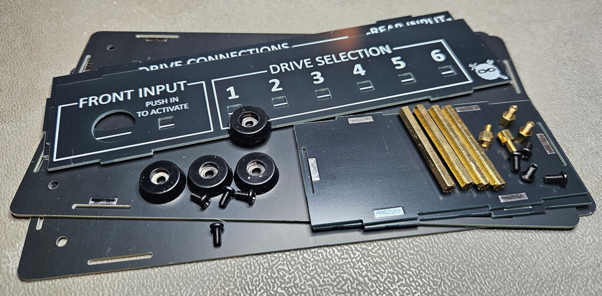
All solder pads should be facing inward and can be used to secure enclosure pad using solder. This shouldn't be necessary and complicates disassembly.
| Qty | Value | Footprint | References |
|---|---|---|---|
| 8 | DIN-6 | DIN-6 multi:DIN-6 multi shielded | J1, J2, J3, J4, J5, J6, J7, J8 |
| 7 | PBH6U | E-Switch_PBH6U:PBH6U | SW1, SW2, SW3, SW4, SW5, SW6, SW7 |
| 4 | MountingHole | MountingHole:MountingHole_3.5mm_Pad_TopBottom | H1, H2, H3, H4 |
| 2 | LOGO | LOGO | G***, G*** |
gusmanb/logicanalyzer
24 channel, 100Msps logic analyzer hardware and software

mntmn/amiga2000-gfxcard
MNT VA2000, an Open Source Amiga 2/3/4000 Graphics Card (Zorro II/III), written in Verilog


hackclub/OnBoard
💡 Join 1,000 teenagers and make your first PCB with a $100 grant!

drandyhaas/KiCadRoutingTools
A set of Python/Rust tools to aid routing in KiCad

Arrow-air/project-quiver
Project Quiver documentation, designs, and project artifacts.


It measures 198.1 × 95.3 mm and has 2 copper layers, 1.6 mm thick.
21 parts. The full list of its parts is on this page, with links to each part's symbol and footprint where PCBKit's library has them.
From the RetroNynjah/IEC-Switch repository on GitHub, at the commit this page was made from: the board is pcb/rev1/kicad schematics/IEC Switch.kicad_pcb and its schematic enclosure/rev1/kicad-schematics/IEC Switch Case Back Rev 1.kicad_sch. PCBKit opens the board in the browser, with nothing to install.
Its repository publishes it under the GPL-3.0 licence: you may reuse it on that licence's terms (keep the author's notice, and for a copyleft licence share your changes alike).