2 layers67.3 × 30.5 mm
2364 Flash ROM programmer rev 3
RetroNynjah/2364-Flash-ROM
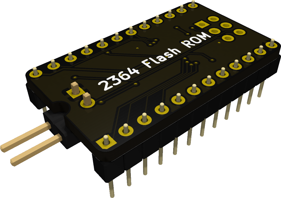
Reprogrammable 2364 ROM replacement
6 parts1GPL-3.0

 RetroNynjah/2364-Flash-ROM1
Reprogrammable 2364 ROM replacement
2364 Flash ROM rev 4 is an open-source printed circuit board by RetroNynjah, from the RetroNynjah/2364-Flash-ROM repository on GitHub, published under the GPL-3.0 licence. It is a 2-layer board of 17.8 × 30.5 mm with 9 parts on 33 nets, routed with 230 tracks and 21 vias.
Its parts include 3 resistors, 3 connectors, 1 capacitor and 1 IC.
Cheap reprogrammable ROM replacement made to replace 24 pin 2364 ROMs in C64/1541 and others.
A single optional jumper (J3) is available for switching between two ROMs.
| identifier | Part | Comments |
|---|---|---|
| U1 | SST39SF010A | TSOP-I-32_11.8x8mm_P0.5mm |
| C1 | 100nF | 0603 ceramic capacitor |
| R1,R2 | 1kOhm | 0603 resistor |
| R3 | 10kOhm | 0603 resistor |
| RN1 | CAY16-103J4LF | 1206 resistor array 4xRes 10kOhm |
| J1 | 1x12p header (2 pcs) | 2.54mm pitch |
| J3 | 1x2p header 90deg | Optional ROM selector jumper |
All components and pins are located on the bottom side of the ROM, maybe with exception for the jumper pins (J3) which may be placed on either side.
The ROM can be programmed using any EPROM programmer that supports the SST39SF010.
A programming adapter is included in this repository.
The programming header J2 on the FLASH ROM needs to be connected to the programming adapter
in addition to the signals that are connected to the socket.

The default ROM image should be placed in the topmost 8kB of the Flash ROM (starting at 0x1E000). For ROM switching, the second ROM image should be placed 8kB before that (starting at 0x1C000). The second ROM image is active when J3 is closed.
| Qty | Value | Footprint | References |
|---|---|---|---|
| 2 | 1k | Resistor_SMD:R_0603_1608Metric_Pad0.98x0.95mm_HandSolder | R1, R2 |
| 1 | 100n | Capacitor_SMD:C_0603_1608Metric_Pad1.08x0.95mm_HandSolder | C1 |
| 1 | 10k | Resistor_SMD:R_Array_Convex_4x0603 | RN1 |
| 1 | 10k | Resistor_SMD:R_0603_1608Metric_Pad0.98x0.95mm_HandSolder | R3 |
| 1 | 2364 Socket | DIP-24_W15.24mm_BottomHeaders:DIP-24_W15.24mm_BottomHeaders | J1 |
| 1 | Prg header | Connector_PinHeader_2.54mm:PinHeader_2x03_P2.54mm_Vertical | J2 |
| 1 | ROM selector | Connector_PinHeader_2.54mm:PinHeader_1x02_P2.54mm_Horizontal | J3 |
| 1 | SST39SF010A | Package_SO:TSOP-I-32_11.8x8mm_P0.5mm | U1 |
RetroNynjah/2364-Flash-ROM
Reprogrammable 2364 ROM replacement


FrameworkComputer/ExpansionCards
Reference designs and documentation to create Expansion Cards for the Framework Laptop

VoronDesign/Voron-Hardware
Cool Hardware designed by the Voron Design group

hackclub/OnBoard
💡 Join 1,000 teenagers and make your first PCB with a $100 grant!


adamws/kicad-kbplacer
KiCad plugin for automatic keyboard's key placement and routing
It measures 17.8 × 30.5 mm and has 2 copper layers, 1.6 mm thick.
9 parts. The full list of its parts is on this page, with links to each part's symbol and footprint where PCBKit's library has them.
From the RetroNynjah/2364-Flash-ROM repository on GitHub, at the commit this page was made from: the board is flash-rom-rev4/kicad schematics/2364 Flash ROM rev 4.kicad_pcb and its schematic flash-rom-rev4/kicad schematics/2364 Flash ROM rev 4.kicad_sch. PCBKit opens the board in the browser, with nothing to install.
Its repository publishes it under the GPL-3.0 licence: you may reuse it on that licence's terms (keep the author's notice, and for a copyleft licence share your changes alike).