
4 layers280 × 200 mm
Main Control Unit
Tuskar-Marine/hardware
All tools for the Mermaid's Rest open sailing tools
409 parts6

 RepRapLtd/Oxygen-concentrator83
Open source oxygen concentrator design
O2-controller is an open-source printed circuit board by RepRapLtd, from the RepRapLtd/Oxygen-concentrator repository on GitHub, published under the GPL-3.0 licence. It is a 2-layer board of 68.6 × 53.3 mm with 34 parts on 49 nets, routed with 127 tracks and 9 vias.
It is built around the DMN6075S. Its parts include 13 connectors, 9 resistors, 9 transistors and 2 capacitors. It belongs with the AVR (ATmega, ATtiny) boards of this library.
This is the RepRap Ltd repository for all the information, designs, and data for our open-source Oxygen Concentrator.
This design is not yet working. We think the problem is that the Zeolite has too much water in it. If you want to take this further, try drying the zeolite in an oven above 100oC, putting it in a sealed container, allowing it to cool, then loading it into the machine.
Version 1 of this (up to commit 422aa3) didn't work because the air was not flowing through the zeolite in a smooth consistent manner under pressure. So this is now work-in-progress on Version 2 (from commit 3a930c0) which we hope will fix the problem.
With the World’s current problems caused by covid-19, it seemed to us that an open-source oxygen concentrator would be a useful thing to have. These are fairly simple devices that work by pressure swing adsorbtion.
The primary aim of this project is to get a working design out. We hope that others will then use that as the basis for improvements and variations. See the How Can You Help section below. This repository now incorporates some ideas from comments to our original blog post about it. A big Thank You to all who have made suggestions; please make more using the issue link above!
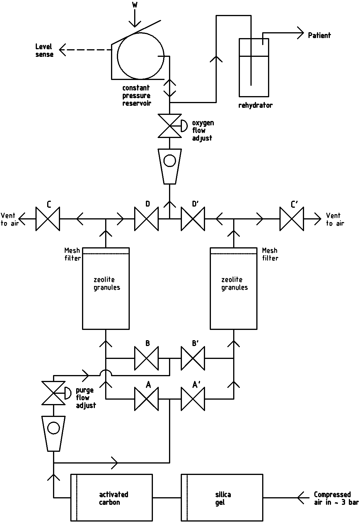
We don't know if it will until we test it, of course. But the plan is this:
Starting bottom right compressed air flows into two chambers to clean it up; silica gel will remove moisture, and activated carbon will remove CO2.
All the valves are normally-closed types. Valves A and D will be opened, which will allow the air to flow under pressure through the zeolite column on the left. The pressure will be set indirectly by adjusting the oxygen-flow-adjust flow regulator. N2 has a large quadrupole moment (an aspect of the pattern of electric charges round the molecule) relative to O2. This means that it “fits” into the surface of zeolite much better and adsorbs onto it in preference, leaving the O2 free in the chamber under pressure. The O2-enriched gas will flow up to the constant pressure reservoir, then through a rehydrator to restore the moisture removed by the silica gel, and on to the patient.
After about 30 seconds or so (exact time to be determined experimentally...) the zeolite will be saturated with N2. Valves A and D will be closed and valves B and C will be opened. This will allow air at atmospheric pressure to flow through the zeolite purging the N2 from it to the surrounding air. The flow rate will be set by the purge-flow-adjust flow regulator.
At the same time as those valve changes the cycle as just described will start for the zeolite column on the right by opening valves A' and D'. Thus the O2 flow will be maintained by the right hand column while the left hand column is purging.
The whole cycle will then repeat, swapping between the left and right columns for as long as the O2 is required.
The level sense signal from the reservoir feeds into a microcontroller (not shown) that opens and closes the valves and handles all the timings. This is an Arduino Uno with a shield PCB with MOSFETs to drive the valves. When the reservoir is full all the A and B valves are closed to shut the process down. When it gets low, the cycles are started again. See the Electronics and Software directories in the repository.
The best zeolite to use for this seems to be 13X, but we are still investigating that.
Both vater vapour and CO2 would reduce the efficiency of the zeolite, and (because of the preferential adsorption of the N2) atmospheric CO2 would also become too concentrated in the output. The active carbon would be purged of adsorbed CO2 from time to time in the same way as the purge described above. The silical gel and maybe the zeolite would have to be dried periodically. The simplest way to do that would probably be to put them in a kitchen oven (electric, not gas…). You would have one set working in the machine, and another set being dried, then swap them over. Silica gel can be obtained including an indicator which changes colour when it gets wet.
The compressed air would be required at the sorts of pressures and flow rates easily achievable by a 12 volt care tyre inflator. All the plumbing is done using push-fit pneumatic connectors and PU pipe.
The best devices to use to contain the zeolite, carbon, and silica gel seem to be refillable in-line filter housing reverse osmosis units (see the bill of materials), which usefully come with 6mm push-fit couplings on the ends and built-in foam filters to retain particles of active material. These will prevent the zeolite granules getting into the valves (or the patient…). It would probably be a good idea if the device was actually arranged as shown with the flow up from the bottom to the top for the same reason. As to size – the whole thing would be about microwave-oven size plus the compressor.
All the valves in the prototype are simple on-off 12-volt normally-closed pneumatic valves. This could almost certainly be simplified in production. For example valves A and B could be combined into a single two-port valve, as could valves C and D. It may even be possible to combine all four into a single rotating sleve valve. This would considerably reduce costs, though the single valves are useful for prototyping as they can be re-purposed between versions of the design.
In the Bill of Materials (see below) we have deliberately linked to non-medical-grade common very-low-cost components and materials of about the quality that one might expect in – say – a child’s swimming snorkel and mask. To be most useful, this thing has to be manufacturable anywhere in the World at low cost. And you trust your child’s life to that snorkel and mask…
Here’s how we see this developing:
We’ll get a version working.
Other people make copies and variations.
We and others make measurements (O2 concentration, CO2 contamination etc).
Fix what’s needed to get those right.
Fix anything needed to get the machine useful
In developing countries, and in the developed world in remote and emergency situations.
In the developed world in hospital and clinic situations.
Note that we explicitly acknowledge that less rigorous standards are appropriate for emergencies than for well-controlled locations, and that that allows more benefit to be obtained than insisting on the highest standard everywhere.
Version 2 is neither final nor prototyped yet, but there is nothing to stop you taking what we have posted here and building it experimentally. But the point where we would appreciate people getting involved is Stage 2. onwards. In particular it’s important that others change the design to make improvements so that the best designs emerge from a large number of experiments (this is what happened with the RepRap Project and is the reason it was so successful).
Bill-of-materials.ods
spreadsheet of materials we used to build our prototype
Useful-information
Useful scientific papers and other materials, suggestions from contributors etc.
Electronics
Kicad design for the Arduino Uno shield that controls the device
LICENSE
GPL V3
Mechanics
FreeCAD designs for 3D printed parts of the machine (mainly simple brackets).
Pix
Images and photographs
README.md
This file
Software
Arduino C++ program to control the machine

http://users.wpi.edu/~mpopovic/pages/OxygenConcentrator.html
http://www.vurup.sk/wp-content/uploads/dlm_uploads/2017/07/pc_3_2013_javadi_221.pdf
https://github.com/oxycon/ProjectApollo
https://www.ou.edu/class/che-design/a-design/projects-2007/Oxygen%20Generator-Presentation.pdf
https://www.who.int/medical_devices/publications/tech_specs_oxygen-concentrators/en/
| Qty | Value | Footprint | References |
|---|---|---|---|
| 13 | Conn_01x02_Male | Connector_PinHeader_2.54mm:PinHeader_1x02_P2.54mm_Vertical | J1, J2, J3, J4, J5, J6, J7, J8, J9, J10, J11, J12, J13 |
| 9 | 10K | Resistor_SMD:R_0805_2012Metric_Pad1.15x1.40mm_HandSolder | R1, R2, R3, R4, R5, R6, R7, R8, R9 |
| 9 | DMN6075S | Package_TO_SOT_SMD:SOT-23 | Q1, Q2, Q3, Q4, Q5, Q6, Q7, Q8, Q9 |
| 1 | 0.1uF | Capacitor_SMD:C_0805_2012Metric | C1 |
| 1 | 220uF | Capacitor_SMD:C_Elec_10x10.2 | C2 |
| 1 | Arduino_UNO_R3_Shield | reprapltd-kicad:Arduino_UNO_R3_Shield | A1 |
Tuskar-Marine/hardware
All tools for the Mermaid's Rest open sailing tools


PecaJosef/PCK-CNC
PCK-CNC is an open-source CNC router designed to offer precision, reliability, and affordability. This machine combines high-performance features with an accessible design that caters to both beginners and CNC…


It measures 68.6 × 53.3 mm and has 2 copper layers, 1.6 mm thick.
34 parts, built around the DMN6075S. The full list of its parts is on this page, with links to each part's symbol and footprint where PCBKit's library has them.
From the RepRapLtd/Oxygen-concentrator repository on GitHub, at the commit this page was made from: the board is Electronics/o2-controller/o2-controller.kicad_pcb. PCBKit opens the board in the browser, with nothing to install.
Its repository publishes it under the GPL-3.0 licence: you may reuse it on that licence's terms (keep the author's notice, and for a copyleft licence share your changes alike).