
2 layers25.8 × 20 mm
TM Warthog Open Analog Slew
ServError/Thrustmaster_Warthog_Throttle_Alps_Slew_Mod
An open source replacement for the terrible TM Warthog Throttle slew stick
10 parts12

 RaysceneNS/SV-650-GearPositionIndicator12
This is a simple circuit that augments the second gen Suzuki SV650 to have a gear position indicator.
Sv650 board is an open-source printed circuit board by RaysceneNS, from the RaysceneNS/SV-650-GearPositionIndicator repository on GitHub. It is a 2-layer board with 10 parts on 16 nets, routed with 56 tracks and 0 vias.
It is built around the ATTINY44A-SSU. Its parts include 3 capacitors, 3 resistors, 3 ICs and 1 connector. It belongs with the AVR (ATmega, ATtiny) boards of this library.
The gear position indicator is a custom hardware project that interfaces with a 2003-2009 suzuki SV 650 and possibly 2004-2011 V Strom 650s (not yet tested) to display the gear position, current ambient temperature and charging system voltage.
The display is designed to look like the stock gauge cluster, it is a very slim light weight unit with an LCD display. The yellow backlight color was specificaly chosen to match the OEM backlighting.
These instructions will get you a copy of the project up and running on your local machine for development and testing purposes. See deployment for notes on how to deploy the project on a live system.
To build the firmware solution you will need Atmel Studio v. 7
To deploy the firmware you will need an in system programmer (ISP) attached to the microcontrollers using the following programming pins.
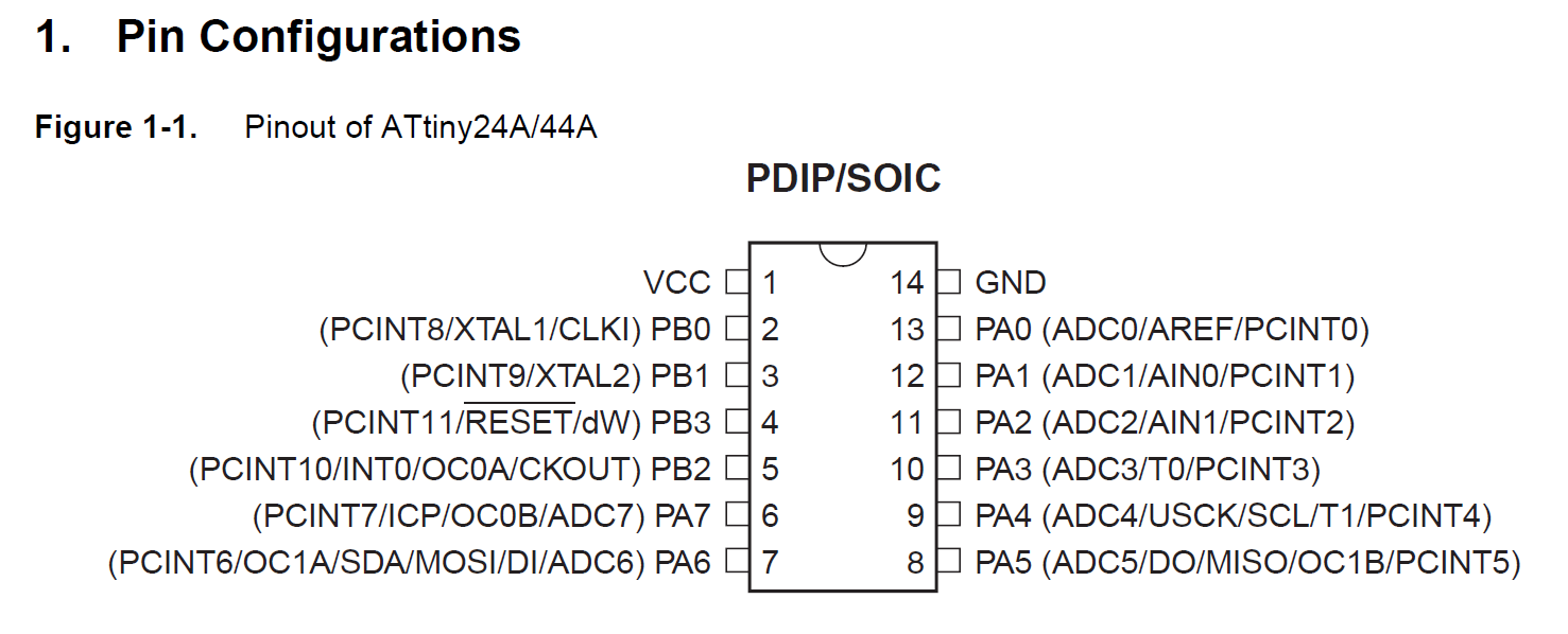
The schematic folder contains a Kicad schematic and board layout to build the hardware. Parts are surface mount and designed to be mounted to a single side circuit board for ease of build.
Power draw of the unit is less than 1/4 watt so there is almost no load to the bikes charging system.
A nokia 5110 LCD screen was chosen as this display offers a low price point combined with an excellent full sun readability.
Wiring interface is a simple three wire setup - ignition power, ground, and gear position level. The hardware is bolted to the head stock just in from of the stock gauge cluster. The mounting box is a black abs plastic project box.
This is the list of components required to build the gear position indicator.
This is what the finished product looks like on the motorcycle.


| Qty | Value | Footprint | References |
|---|---|---|---|
| 2 | 10K | Resistors_SMD:R_0805 | R2, R4 |
| 1 | 0.1u | Capacitors_SMD:C_0805 | C1 |
| 1 | 0.1uF | Capacitors_SMD:C_0805 | C3 |
| 1 | 10uF | Capacitors_SMD:C_0805 | C2 |
| 1 | 47K | Resistors_SMD:R_0805 | R3 |
| 1 | ATTINY44A-SSU | Housings_SOIC:SOIC-14_3.9x8.7mm_Pitch1.27mm | U2 |
| 1 | Conn_01x08 | Socket_Strips:Socket_Strip_Straight_1x08_Pitch2.54mm | J1 |
| 1 | LM2936-3.3 | TO_SOT_Packages_SMD:SOT-223-3_TabPin2 | U1 |
| 1 | MCP9700AT-E/TT | TO_SOT_Packages_SMD:SOT-23 | U4 |
ServError/Thrustmaster_Warthog_Throttle_Alps_Slew_Mod
An open source replacement for the terrible TM Warthog Throttle slew stick


danlil666/documentation
This is the starting point of me trying to use GitHub.

TheBeachLab/alphabets
Open Source Mechanical Split Flap Display, AKA Solari display

gusmanb/logicanalyzer
24 channel, 100Msps logic analyzer hardware and software

byrantech/laptop
anyon_e, a highly integrated, high end, open source laptop. Attempt the impossible.

joeycastillo/Sensor-Watch
A board replacement for the classic Casio F-91W wristwatch

10 parts, built around the ATTINY44A-SSU. The full list of its parts is on this page, with links to each part's symbol and footprint where PCBKit's library has them.
From the RaysceneNS/SV-650-GearPositionIndicator repository on GitHub, at the commit this page was made from: the board is schematic/sv650 board.kicad_pcb. PCBKit opens the board in the browser, with nothing to install.
Its repository states no licence, so its author keeps all rights: ask RaysceneNS before reusing the design.