6 layers50 × 50 mm
Flight Computer
jainamnahar14surat/Flight-Computer
A compact, custom-designed PCB (Printed Circuit Board) for a Flight Computer, aimed at aerospace applications like model rockets, UAVs, and experimental aircrafts.
76 partsMIT

 Raetti/GPSM9N_PCB
u-blox NEO-M9N GNSS Receiver Breakout PCB (KiCad 10)
GPSM9N is an open-source printed circuit board by Raetti, from the Raetti/GPSM9N_PCB repository on GitHub. It is a 4-layer board of 55.5 × 41.5 mm with 13 parts on 26 nets, routed with 21 tracks and 0 vias.
It is built around the NEO-M9N-00B and AMS1117-3.3. Its parts include 3 capacitors, 3 resistors, 2 ICs, 2 diodes and 2 connectors. It belongs with the radio and wireless and interfaces and adapters boards of this library.





A compact breakout and development board for the u-blox NEO-M9N multi-constellation GNSS (GPS, GLONASS, Galileo, BeiDou) receiver module, featuring direct USB-C connectivity, 3.3V on-board regulation, an SMA antenna port, PPS indicator LED, and an external MCU host header.
[!WARNING] DEVELOPMENT / UNFINISHED STATE (DO NOT FABRICATE AS-IS) This repository represents an early prototype in active development. The PCB routing is incomplete and the schematic contains several known electrical and footprint errata (listed in detail under Known Issues & Errata). Do not order or manufacture these board files until Revision 1.0 is finalized.
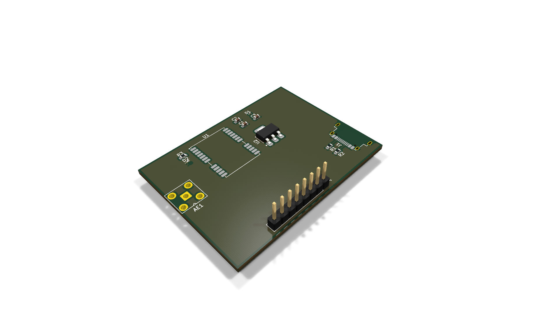
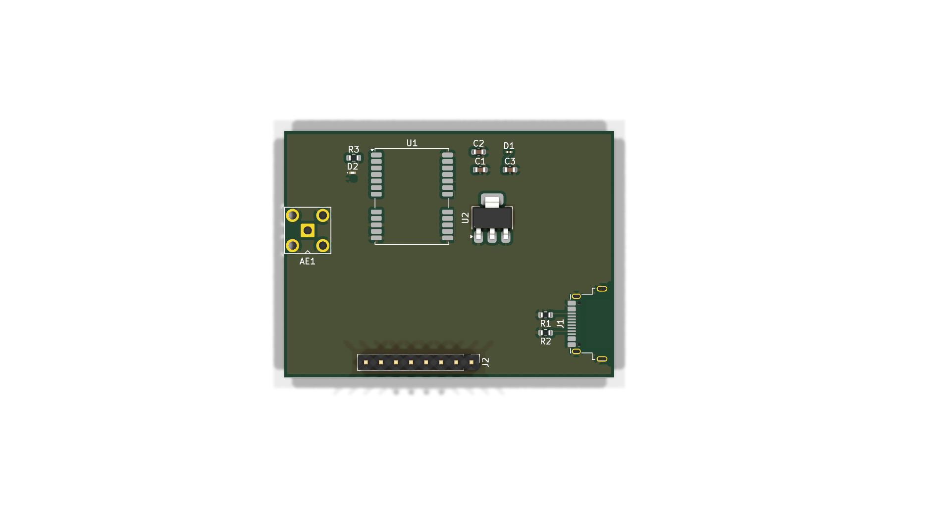
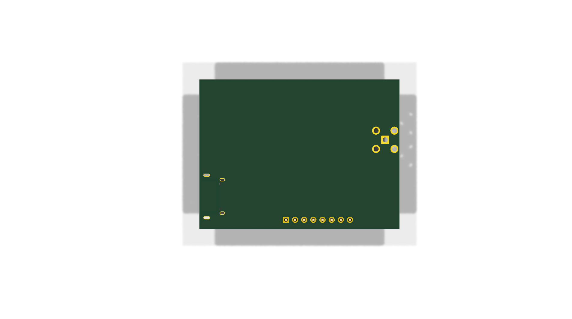
U1) supporting concurrent reception of up to 4 GNSS constellations with up to 25 Hz update rates.J1) for computer connectivity, testing, and configuration using u-blox u-center.U2) converting 5V USB VBUS down to 3.3V.AE1) for external passive or active GNSS antennas.J2): 8-pin breakout for interfacing with external microcontrollers via UART, I2C, or SPI.D2) tied to the TIMEPULSE (Pulse-Per-Second / 1PPS) output.| Specification | Value | Notes |
|---|---|---|
| Dimensions | 55.5 mm × 41.5 mm | Board bounding box |
| Layer Stackup | 4 Layers (F.Cu, In1.Cu, In2.Cu, B.Cu) | 1.6 mm FR4 |
| Supply Input | 5.0 V DC | Via USB-C receptacle (VBUS) |
| Operating Logic Level | 3.3 V | Compatible with 3.3V microcontrollers |
| GNSS Receiver | u-blox NEO-M9N | L1 band (GPS, GLONASS, Galileo, BeiDou) |
| Antenna Connector | Standard SMA Female (Jack) | 50 Ω nominal |
J2 — External MCU Header (2.54mm Pitch)| Pin # | Pin Name | Module Pin | Direction | Description |
|---|---|---|---|---|
| 1 | GPS_TX/MISO | Pin 20 | Output | UART TX / SPI MISO |
| 2 | GPS_RX/MOSI | Pin 21 | Input | UART RX / SPI MOSI |
| 3 | GPS_SDA/CS | Pin 18 | I/O | I2C SDA / SPI Chip Select (Active Low) |
| 4 | GPS_SCL/CLK | Pin 19 | Input | I2C SCL / SPI Clock |
| 5 | GPS_EXTINT | Pin 4 | Input | External Interrupt / Time Mark pin |
| 6 | GPS_SAFEBOOT | Pin 1 | Input | Safeboot Mode pin (active low) |
| 7 | GPS_RST | Pin 8 | Input | System Reset (active low) |
| 8 | GPS_DSEL | Pin 2 | Input | Interface Select (High: UART/I2C, Low: SPI) |
(Note: See Known Issues regarding the addition of dedicated GND and VCC pins to this header in Rev 1.0).
J1 — USB-C Interface (14-Pin USB 2.0)| Pin | Function | Description |
|---|---|---|
A4, B4, A9, B9 | VBUS | 5V Power Input from USB Host |
A1, B1, A12, B12, SH | GND | Power & Chassis Ground |
A5 | CC1 | 5.1kΩ pull-down to GND (Configuration Channel 1) |
B5 | CC2 | 5.1kΩ pull-down to GND (Configuration Channel 2) |
A6, B6 | USB_DP | USB 2.0 Differential Data Plus |
A7, B7 | USB_DM | USB 2.0 Differential Data Minus |
The following issues are tracked and scheduled for resolution in Revision 1.0:
D1 Placement:
+3.3V (near the module's brownout threshold).D1 from the 3.3V output rail; move protection to the 5V VBUS input.J1 Pins B6 / B7):
USB_DP) and A7 to B7 (USB_DM).J2:
J2 to 10 pins to include GND and +3.3V.D1 & D2):
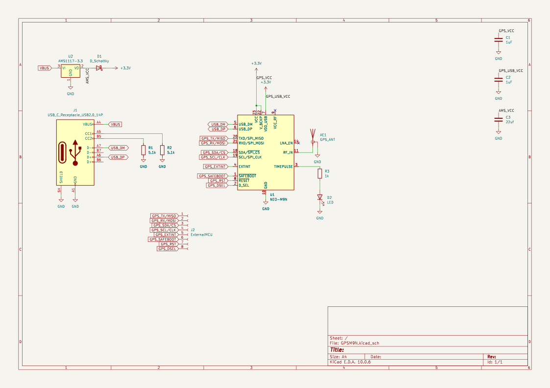
D1 has a capacitor footprint, and D2 is set to 0201 metric (0.6mm × 0.3mm).D_SOD-123 for D1 and LED_0603_1608Metric for D2.VBUS before U2.U2.Edge.Cuts or swap to a surface-mount receptacle.View the complete Schematic PDF or preview the vector diagram below:
| Ref | Value | Package | Description |
|---|---|---|---|
U1 | NEO-M9N | ublox_NEO | Multi-Constellation GNSS Receiver Module |
U2 | AMS1117-3.3 | SOT-223-3 | 3.3V 1A Low Dropout Linear Regulator |
AE1 | GPS_ANT | SMA_BAT_Wireless_BWSMA-KWE-Z001 | Edge-Mount SMA Female Connector |
J1 | USB_C_Receptacle_USB2.0_14P | Amphenol_12401948E412A | USB Type-C Receptacle |
J2 | ExternalMCU (1x08) | PinHeader_1x08_P2.54mm_Vertical | 2.54mm Host Breakout Header |
D1 | D_Schottky | SOD-123 (pending fix) | Reverse protection diode |
D2 | LED (Green) | 0603 (pending fix) | 1PPS Status Indicator |
R1, R2 | 5.1kΩ | 0603 | USB-C CC Pull-Down Resistors |
R3 | 1kΩ | 0603 | LED Current-Limiting Resistor |
C1, C2 | 1 µF | 0603 | Decoupling Capacitors |
C3 | 22 µF | 0603 | LDO Output Bulk Capacitor |
This repository includes a GitHub Actions CI Workflow that automatically runs on every push:
build/gerbers.zip).bom.csv and centroid pos.csv).├── .github/workflows/
│ └── kicad-ci.yml # Automated CI/CD pipeline
├── docs/
│ ├── images/
│ │ ├── pcb_isometric.png # 3D raytraced isometric render
│ │ ├── pcb_top.png # 3D top render
│ │ ├── pcb_bottom.png # 3D bottom render
│ │ └── GPSM9N.svg # Vector schematic diagram
│ └── GPSM9N_schematic.pdf # Complete schematic PDF
├── GPSM9N.kicad_pro # KiCad project file
├── GPSM9N.kicad_sch # KiCad schematic file
├── GPSM9N.kicad_pcb # KiCad layout file
├── .gitignore # KiCad git ignore rules
└── README.md # Hardware documentation| Qty | Value | Footprint | References |
|---|---|---|---|
| 2 | 1uF | Capacitor_SMD:C_0603_1608Metric | C1, C2 |
| 2 | 5.1k | Resistor_SMD:R_0603_1608Metric | R1, R2 |
| 1 | 1k | Resistor_SMD:R_0603_1608Metric | R3 |
| 1 | 22uf | Capacitor_SMD:C_0603_1608Metric | C3 |
| 1 | AMS1117-3.3 | Package_TO_SOT_SMD:SOT-223-3_TabPin2 | U2 |
| 1 | D_Schottky | Capacitor_SMD:C_0201_0603Metric | D1 |
| 1 | ExternalMCU | Connector_PinHeader_2.54mm:PinHeader_1x08_P2.54mm_Vertical | J2 |
| 1 | GPS_ANT | Connector_Coaxial:SMA_BAT_Wireless_BWSMA-KWE-Z001 | AE1 |
| 1 | LED | LED_SMD:LED_0201_0603Metric | D2 |
| 1 | NEO-M9N | RF_GPS:ublox_NEO | U1 |
| 1 | USB_C_Receptacle_USB2.0_14P | Connector_USB:USB_C_Receptacle_Amphenol_12401948E412A | J1 |
jainamnahar14surat/Flight-Computer
A compact, custom-designed PCB (Printed Circuit Board) for a Flight Computer, aimed at aerospace applications like model rockets, UAVs, and experimental aircrafts.


averywallis/Feather-NEO-M9N-GPS
KiCad files for a NEO-M9N GPS Featherwing

Project-SkyFall/CanSat-2023
This is repository for Czech CanSat team Project SkyFall

DashSight/Pine64-Mezzanine-Card
A PineA64 mezzanine card for adding support to communicate with a vehicle's OBD2 port, obtain GPS location and determine acceleration, designed in KiCAD

Sphyrna-029/Pico-Pilot
A simple auto pilot for land/water based robots based on the Raspberry Pi rp2350B/2354B

daedalus-ind/icarus-hardware
Hardware of the onboard flight computer for the Icarus rocket.

DevKiDCosmo/SATELLITE-EDGE-MODULE
A satellite edge module ready for competition
It measures 55.5 × 41.5 mm and has 4 copper layers, 1.6 mm thick.
13 parts, built around the NEO-M9N-00B and AMS1117-3.3. The full list of its parts is on this page, with links to each part's symbol and footprint where PCBKit's library has them.
From the Raetti/GPSM9N_PCB repository on GitHub, at the commit this page was made from: the board is GPSM9N.kicad_pcb and its schematic GPSM9N.kicad_sch. PCBKit opens the board in the browser, with nothing to install.
Its repository states no licence, so its author keeps all rights: ask Raetti before reusing the design.