Skip to the content
4 layers50.8 × 50.8 mmAutomotive Turn Indicator Controller, the printed circuit board in 3D

Automotive Turn Indicator Controller

RINCY-MENEZES/Automotive_Turn_Indicator_Controller

Automotive turn indicator and hazard light controller PCB featuring protected signal inputs, onboard regulated power supply, and high-side output drivers for left and right indicator lamps.

Size
50.8 × 50.8 mm
Copper layers
4
Thickness
1.6 mm
Parts
53
Nets
45
Pads
149
Tracks, vias
110, 7
Pours
16
Routed
Yes
KiCad
KiCad 9.0 (file 20241229)
Created
19 Jul 2026
Updated
21 Jul 2026

Overview

Automotive Turn Indicator Controller is an open-source printed circuit board by RINCY-MENEZES, from the RINCY-MENEZES/Automotive_Turn_Indicator_Controller repository on GitHub. It is a 4-layer board of 50.8 × 50.8 mm with 53 parts on 45 nets, routed with 110 tracks and 7 vias.

It is built around the BZT52-C4V7X, RB168MM150TFTR and VS28VUA1LAMTR, with the MUR1540G-SPT and PJA3415A-AU_R1_000A1 among its other parts. Its parts include 19 resistors, 13 capacitors, 10 diodes, 3 ICs and 2 connectors.

Main components

5

README

README.md

Automotive Turn Indicator Controller

Project Status: 🚧 Work in Progress

A custom automotive turn indicator controller PCB designed using KiCad 9.0. The project focuses on developing a compact and reliable controller for left turn, right turn, and hazard light operations using automotive-grade components and PCB design practices.


Overview

This project demonstrates the complete PCB design workflow, including:

  • Circuit schematic design
  • PCB layout development
  • Custom component integration
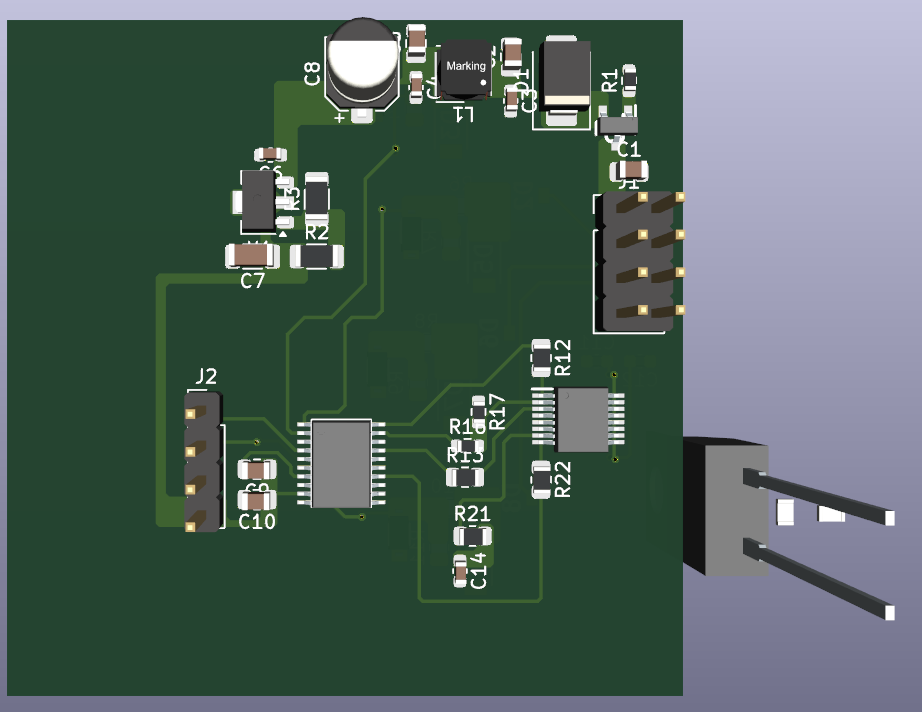
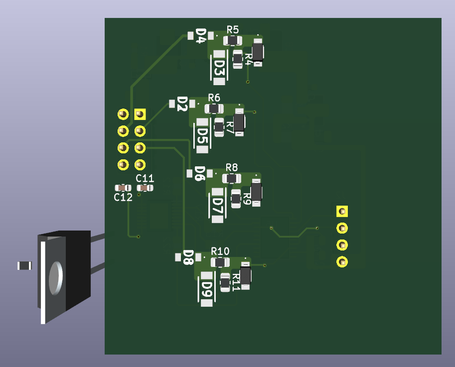
  • 3D PCB visualization

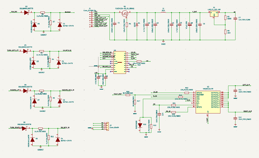
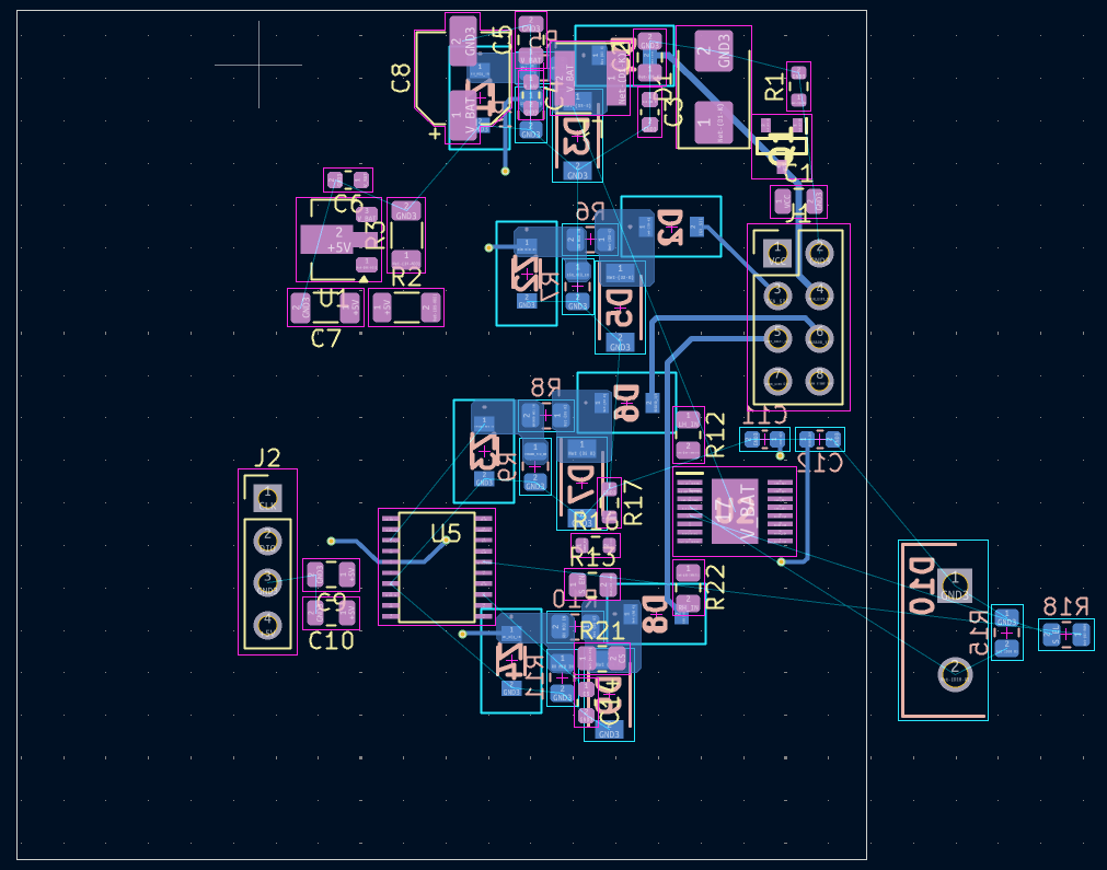
The PCB is currently under development, with schematic capture completed and PCB routing in progress.


Features

  • Left and right turn signal control
  • Hazard light control
  • Automotive input protection circuitry
  • Integrated voltage regulation
  • Custom imported KiCad components
  • Compact PCB layout
  • 3D PCB model generation

Tools Used

  • KiCad 9.0
  • Custom KiCad Symbols & Footprints
  • 3D Component Models

Project Structure

text
Automotive_Turn_Indicator_Controller/
│
├── Images/
│   ├── Schematic.png
│   ├── Layout.png
│   ├── 3D_Top.png
│   └── 3D_Bottom.png
│
├── Comp_Imported/
│
├── Automotive_Turn_Indicator_Controller.kicad_sch
├── Automotive_Turn_Indicator_Controller.kicad_pcb
├── Automotive_Turn_Indicator_Controller.kicad_pro
└── README.md

PCB Design Preview

Schematic

Schematic

PCB Layout

PCB Layout

3D Top View

3D Top

3D Bottom View

3D Bottom


Current Progress

  • ✅ Schematic Design Completed
  • ✅ Component Placement Completed
  • 🚧 PCB Routing in Progress
  • ⏳ Final DRC Verification
  • ⏳ Gerber File Generation

Future Improvements

  • Complete PCB routing optimization
  • Perform final Design Rule Check (DRC)
  • Generate manufacturing Gerber files
  • Prototype fabrication and hardware validation

Author

Rincy Menezes

Parts

53
QtyValueFootprintReferences
81k/6.5W/0805Resistor_SMD:R_0805_2012MetricR4, R5, R6, R7, R8, R9, R10, R11
415K/0.5W/0805Resistor_SMD:R_0805_2012MetricR12, R13, R21, R22
4BZT52-C4V7XBZT52-C4V7X:BZT52C4V7XZ1, Z2, Z3, Z4
4RB168MM150TFTRRB168MM150TFTR:RB168MM150TFTRD2, D4, D6, D8
4VS28VUA1LAMTRVS28VUA1LAMTR:SODFL4725X105ND3, D5, D7, D9
34.7uF/25V/0805Capacitor_SMD:C_0805_2012MetricC2, C5, C10
20R/0.25W/0603Resistor_SMD:R_0603_1608MetricR16, R17
2100nF/25V/0603Capacitor_SMD:C_0603_1608MetricC3, C4
210nF/25V/0603Capacitor_SMD:C_0603_1608MetricC11, C12
1100nF/100V/0805Capacitor_SMD:C_0805_2012MetricC1
1100nF/25V/0805Capacitor_SMD:C_0805_2012MetricC9
1100nF/25V/0805Capacitor_SMD:C_0603_1608MetricC6
110k/0.25W/0603Resistor_SMD:R_0603_1608MetricR1
110nF/25V/0805Capacitor_SMD:C_0603_1608MetricC14
115k/0.5W/0805Resistor_SMD:R_0805_2012MetricR18
11uF/25V/1206Capacitor_SMD:C_1206_3216MetricC7
12KRResistor_SMD:R_1206_3216MetricR3
14.7K/0.5W/0805Resistor_SMD:R_0805_2012MetricR15
147uF/50VCapacitor_SMD:CP_Elec_5x5.9C8
1500RResistor_SMD:R_1206_3216MetricR2
18uHInductor_SMD_Wurth:L_Wurth_WE-LQSH-4020L1
1Conn_01x04Connector_PinHeader_2.54mm:PinHeader_1x04_P2.54mm_VerticalJ2
1Conn_01x08_PinConnector_PinHeader_2.54mm:PinHeader_2x04_P2.54mm_VerticalJ1
1LM317L_SOT-89Package_TO_SOT_SMD:SOT-89-3U1
1MUR1540GMUR1540G:TO533P482X997X1956-2PD10
1PJA3415A-AU_R1_000A1PJA3415A-AU_R1_000A1 +-12V,4.5A,88mohms PMOS:SOT95P240X110-3NQ1
1S2JTRDiode_SMD:D_SMBD1
1VND9016AJTRVND9016AJTR:SOP50P600X170-17NU2
1~MM32F0010A1T:MM32F0010A1TU5

Similar boards

  • 2 layers38.2 × 43.9 mmBuck Converter PCB, the printed circuit board in 3D

    Buck Converter PCB

    RINCY-MENEZES/Buck_Converter_PCB

    Compact DC-DC buck converter PCB using the AP1534 switching regulator with reverse polarity protection, Schottky rectification, LC filtering, and low-ripple regulated output.

    25 parts
  • 4 layers28.7 × 26 mmMinifoc esc, the printed circuit board in 3D

    Minifoc esc

    murexrobotics/electrical

    Highly integrated electronics design and printed circuit boards (PCBs) for the MATE ROV Competition. Attempt the impossible.

    53 parts192MIT
  • 4 layers115 × 85.8 mmPCIe Adapter, the printed circuit board in 3D

    PCIe Adapter

    ECP5-PCIe/ECP5-PCIe

    Mirror of https://codeberg.org/ECP5-PCIe/ECP5-PCIe

    53 parts103
  • 4 layers14 × 16.5 mmTLM v1, the printed circuit board in 3D

    TLM v1

    azerimaker/Penguino-SAMR34

    This repo contains all the necessary design and fabrication files for the Penguino SAMR34 RF module and its Feather breakout board.

    53 parts61
  • 4 layers40 × 23 mmGPDI ULX3S, the printed circuit board in 3D

    GPDI ULX3S

    goran-mahovlic/ulx3s-extensions

    PMOD boards for ULX3S

    53 parts49
  • 4 layers120.6 × 72.4 mmBoard main, the printed circuit board in 3D

    Board main

    analogdevicesinc/education_tools

    Tools for education related platforms

    53 parts45
  • 4 layers172.7 × 135.9 mmJJ65c02, the printed circuit board in 3D

    JJ65c02

    jimjag/JJ6502

    My 6502 Based Breadboard Project

    53 parts26MIT

Questions

How big is the Automotive Turn Indicator Controller PCB?

It measures 50.8 × 50.8 mm and has 4 copper layers, 1.6 mm thick.

What parts does the Automotive Turn Indicator Controller use?

53 parts, built around the BZT52-C4V7X, RB168MM150TFTR, VS28VUA1LAMTR and MUR1540G-SPT. The full list of its parts is on this page, with links to each part's symbol and footprint where PCBKit's library has them.

Where can I download the Automotive Turn Indicator Controller KiCad files?

From the RINCY-MENEZES/Automotive_Turn_Indicator_Controller repository on GitHub, at the commit this page was made from: the board is Automotive_Turn_Indicator_Controller.kicad_pcb and its schematic Automotive_Turn_Indicator_Controller.kicad_sch. PCBKit opens the board in the browser, with nothing to install.

Can I use the Automotive Turn Indicator Controller design in my own project?

Its repository states no licence, so its author keeps all rights: ask RINCY-MENEZES before reusing the design.