
2 layers31.5 × 96.7 mm

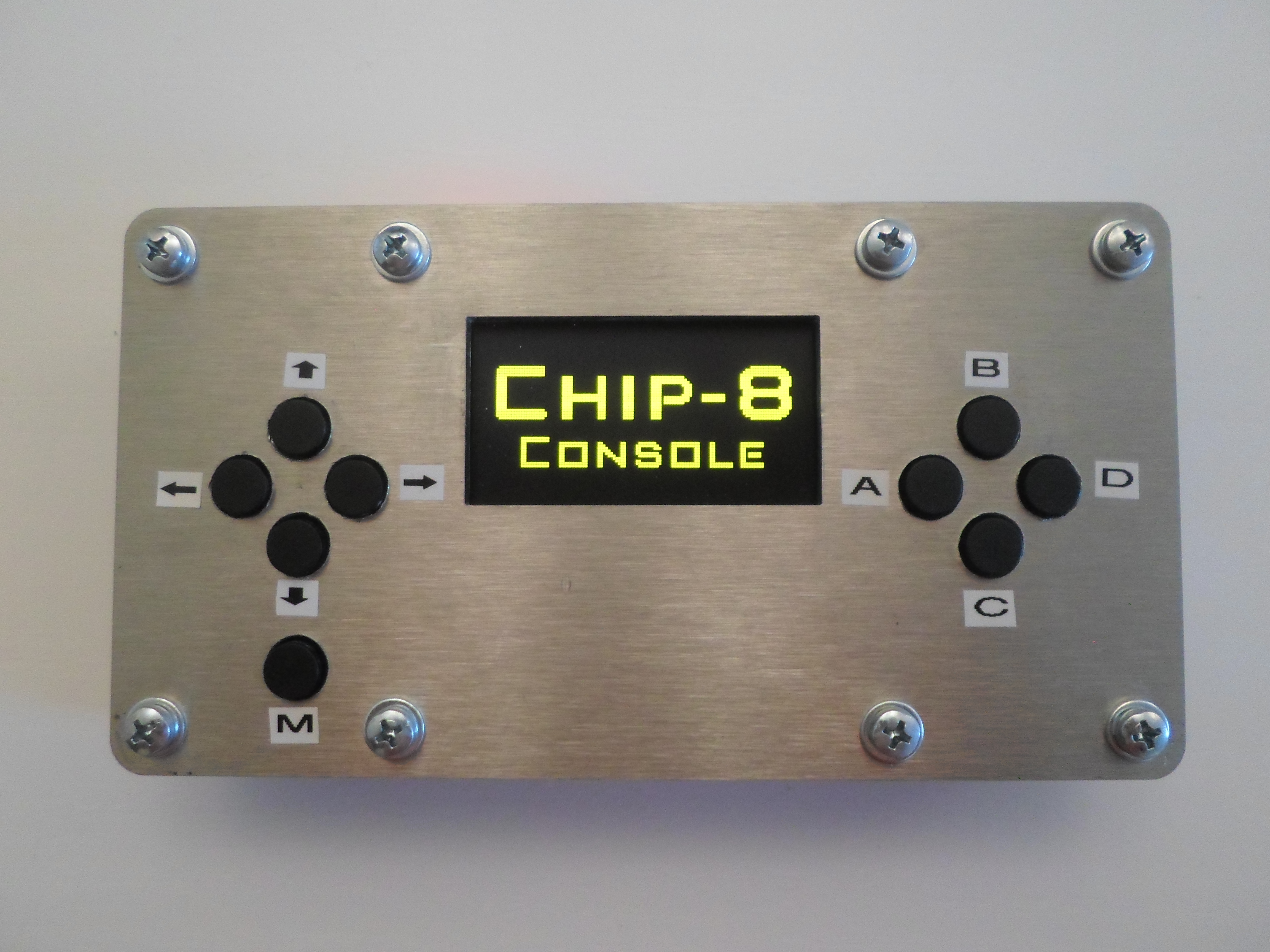
A Chip-8 / Super Chip-8 console powered by a 8-bit PIC18 microcontroller.
Console is an open-source printed circuit board by RICCIARDI-Adrien, from the RICCIARDI-Adrien/Chip8_Console repository on GitHub, published under the MIT licence. It is a 2-layer board of 166 × 81 mm with 72 parts on 40 nets, routed with 533 tracks and 91 vias.
It is built around the TPS613221ADBV, DM1B-DSF-PEJ(92) and D6R90F1LFS, with the 1286AS-H-2R2M=P2, 150080SS75000 and CMT-1604-SMT-TR among its other parts. Its parts include 23 capacitors, 21 resistors, 10 switches, 5 connectors and 2 ICs. It belongs with the retro computing and games boards and the PIC boards of this library.


A Chip-8/SuperChip-8 console powered by a 8-bit PIC18 microcontroller.
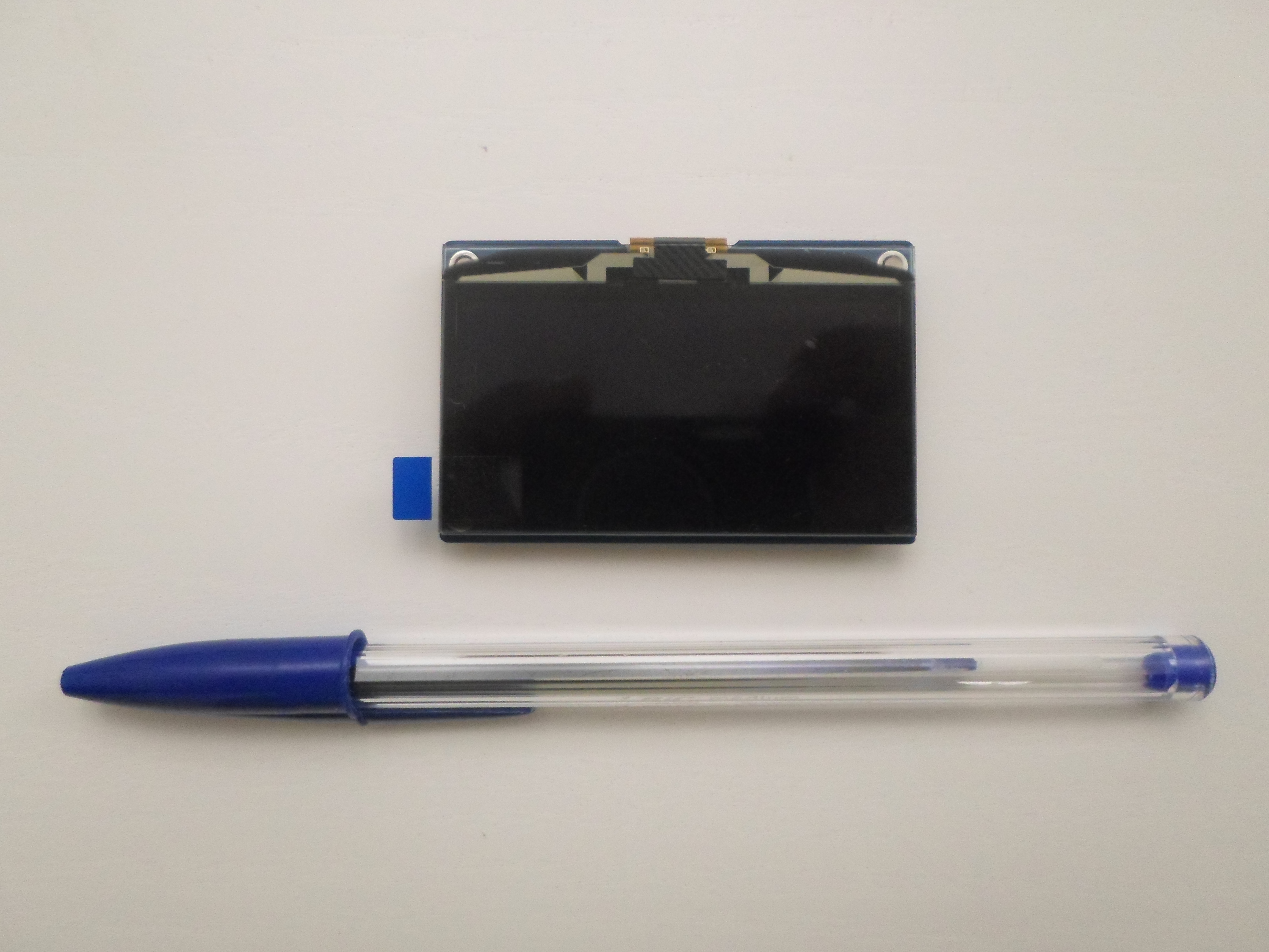
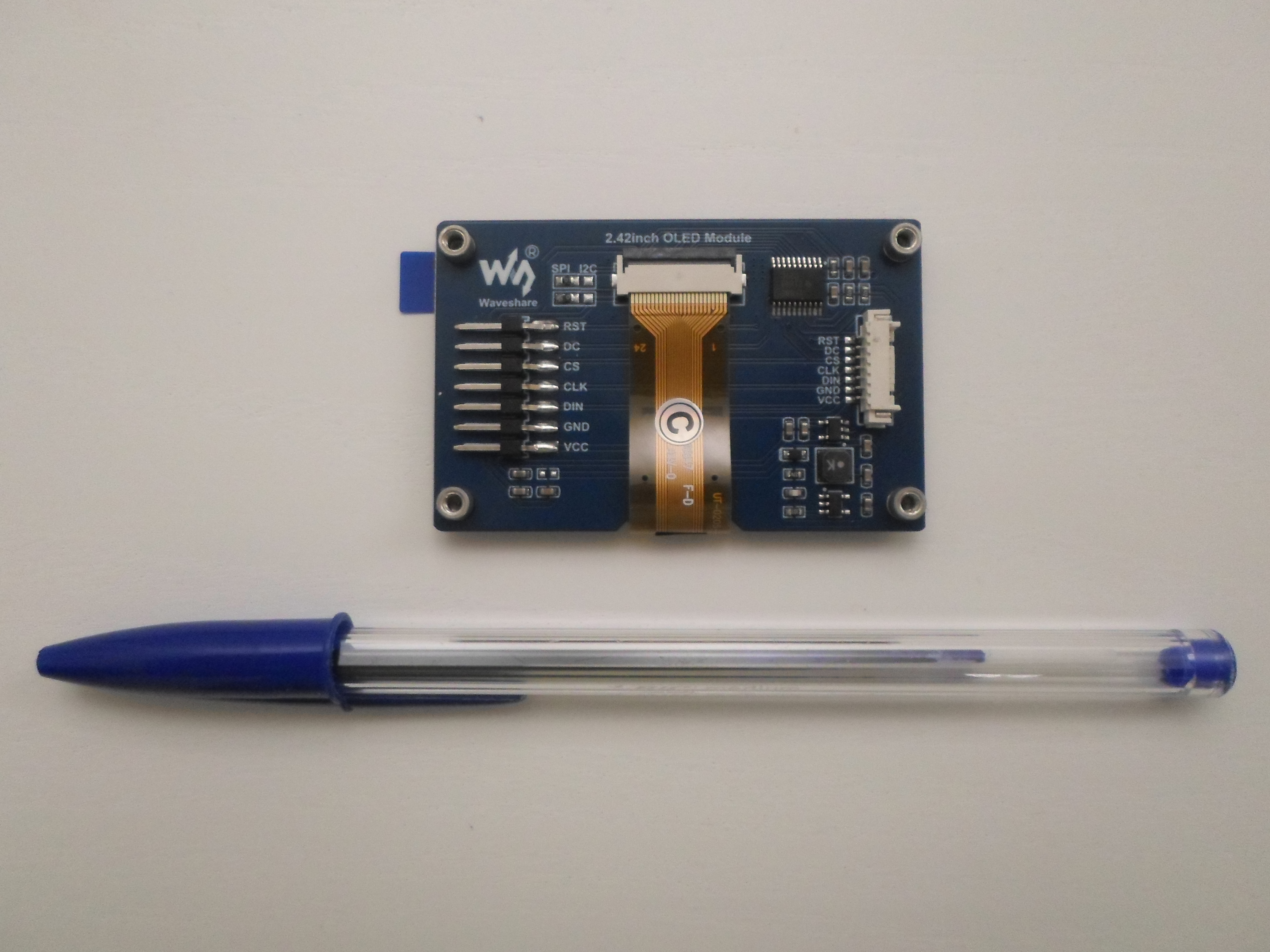
Display module :
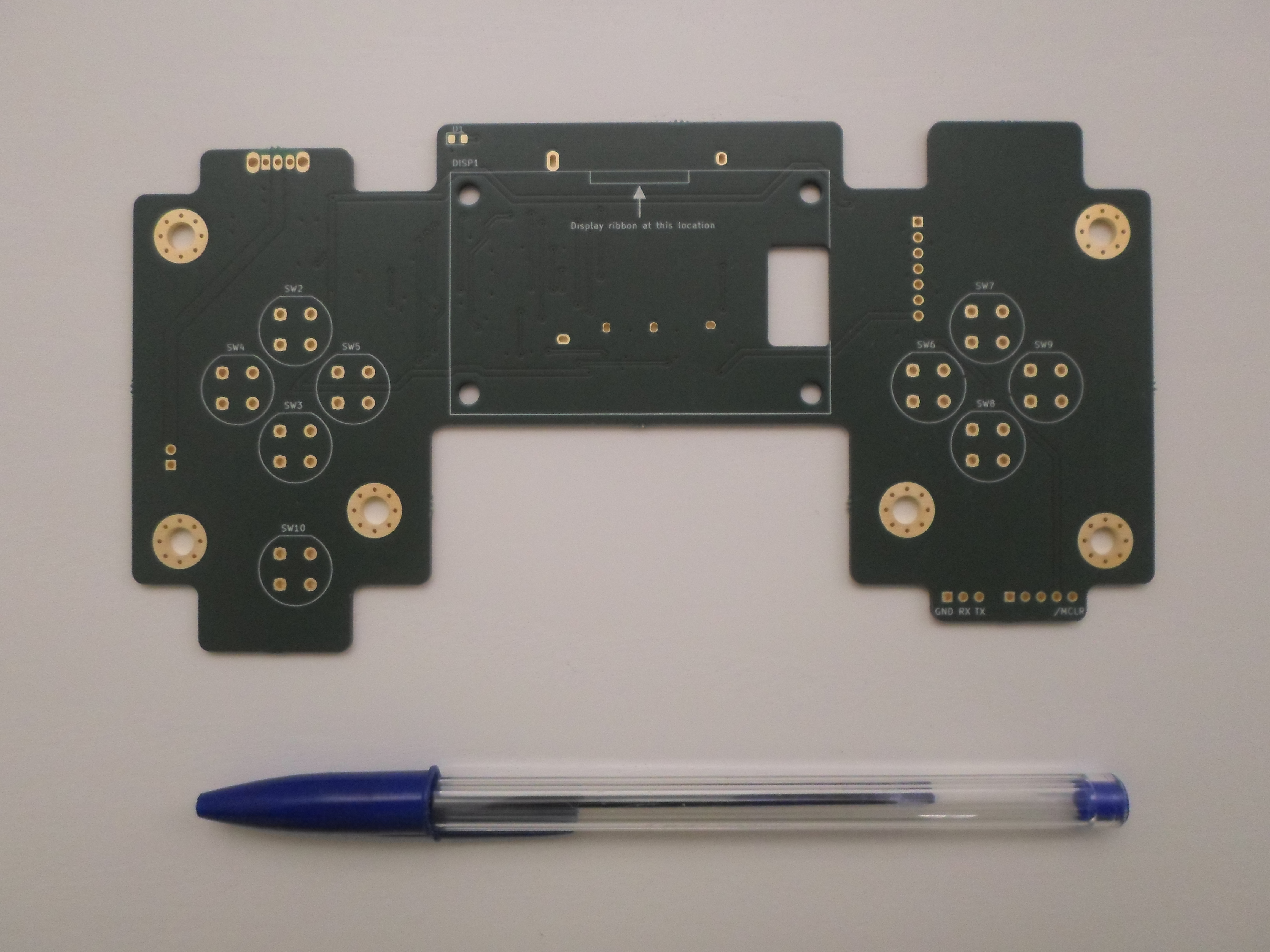
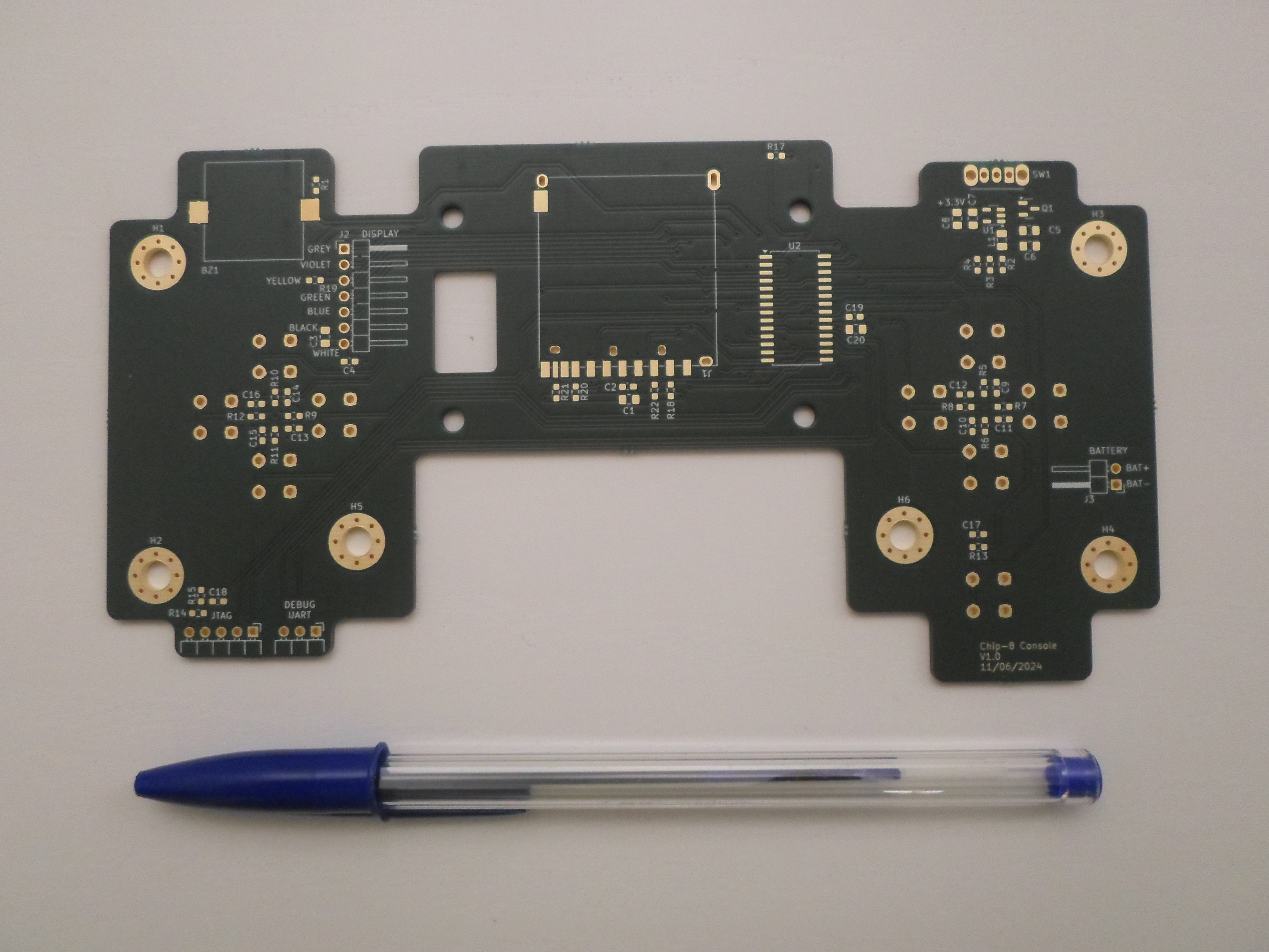
Bare PCB :
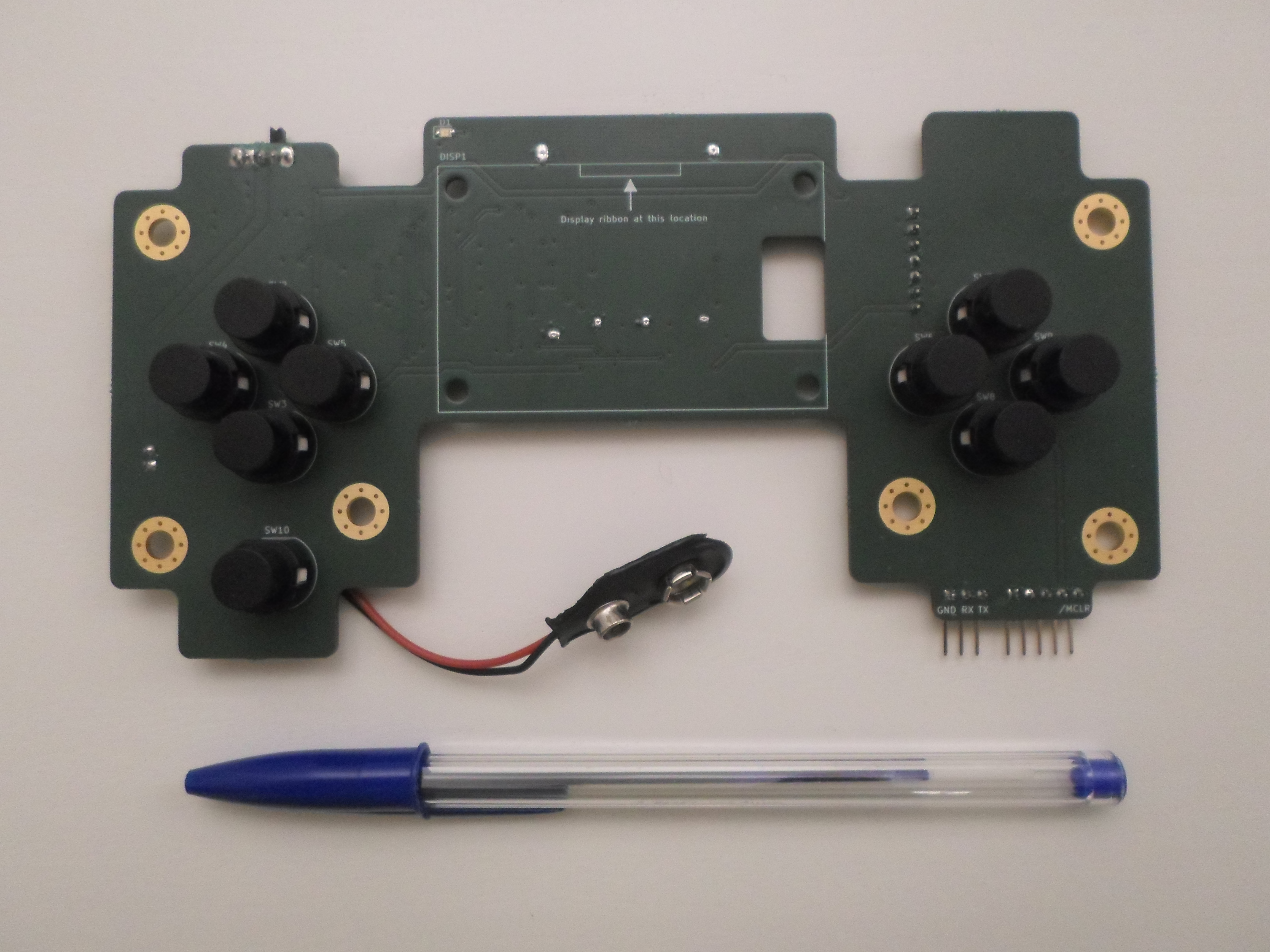
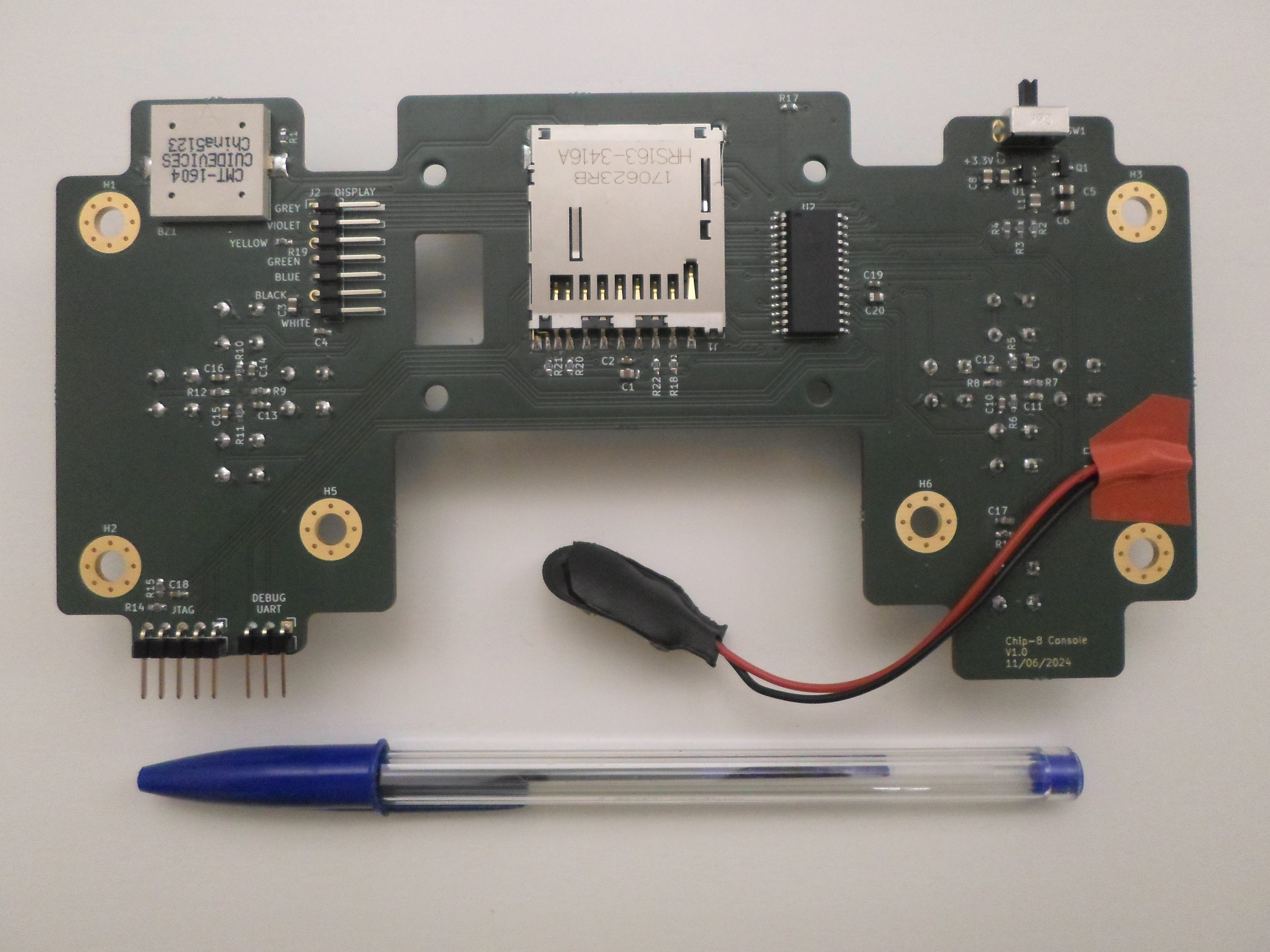
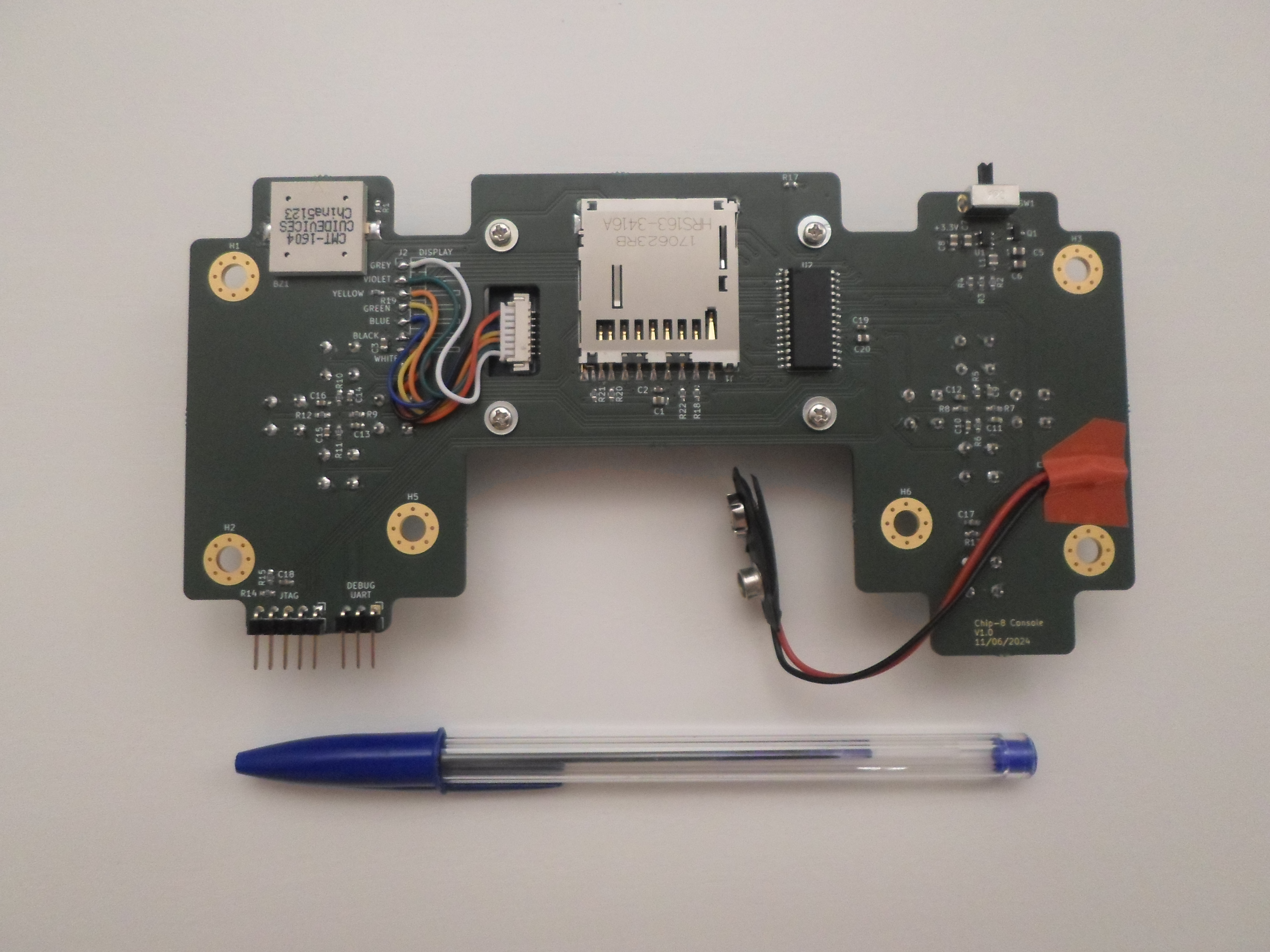
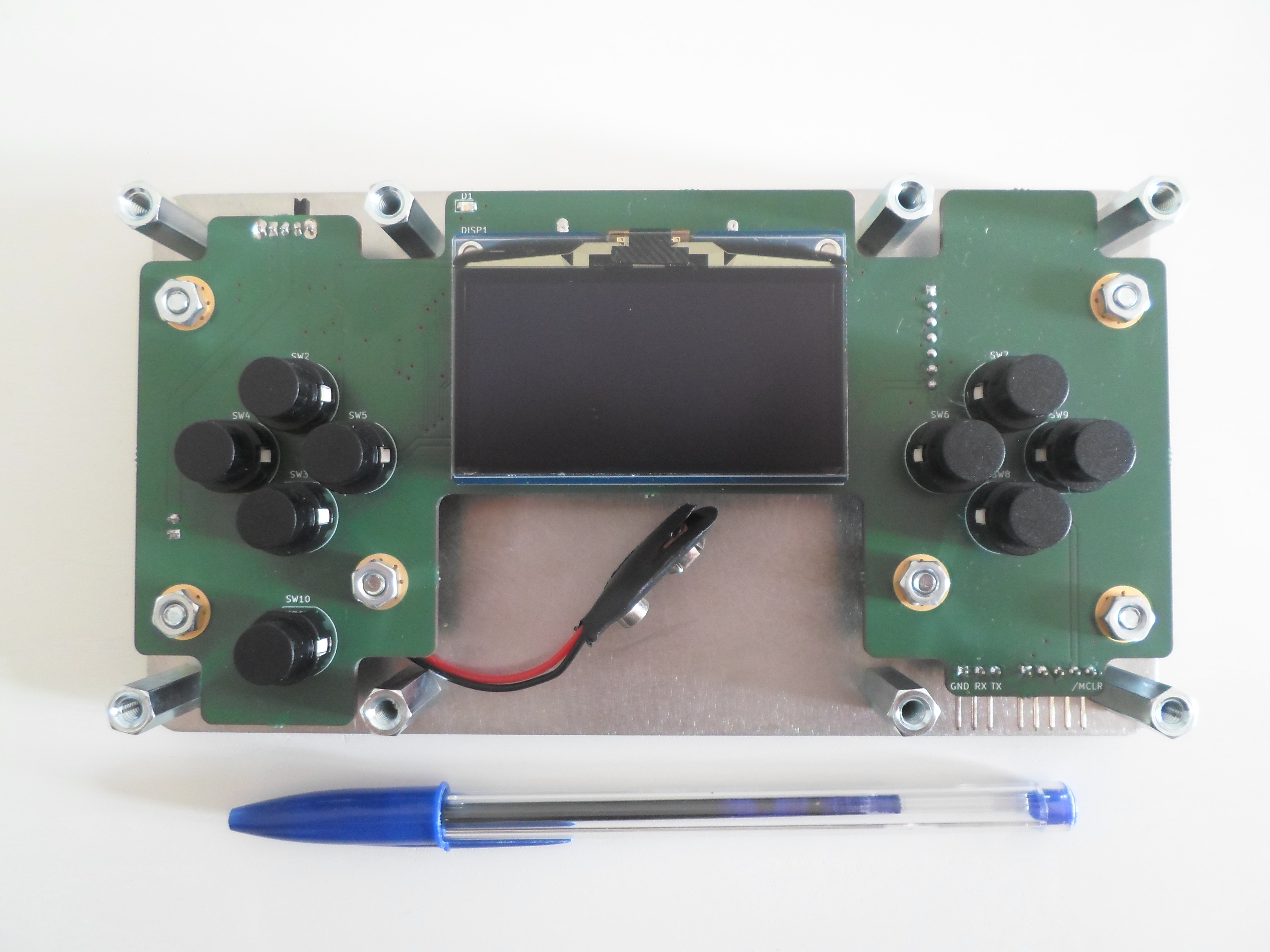
Assembled PCB :
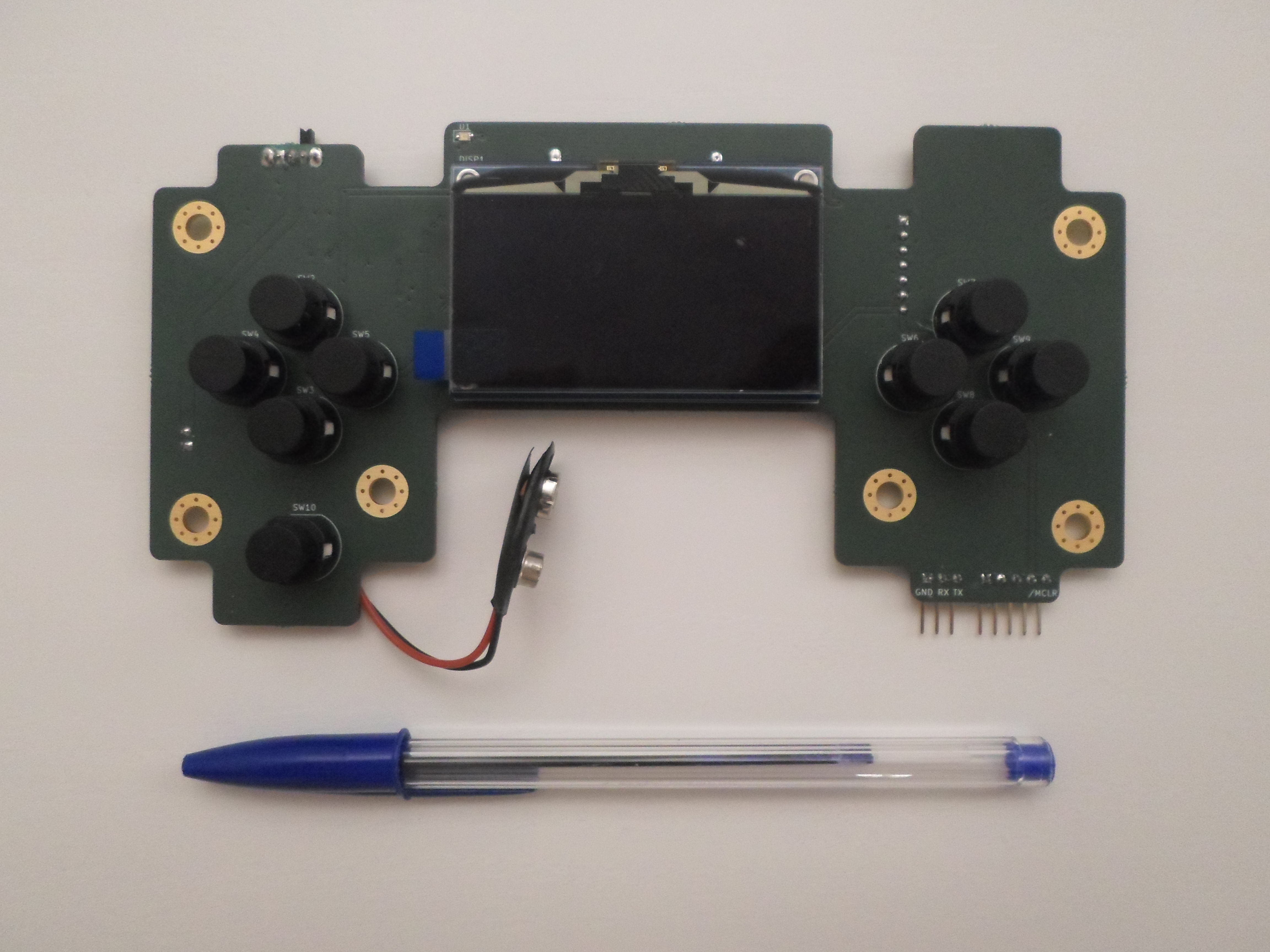
Assembled PCB with the display module screwed and connected :
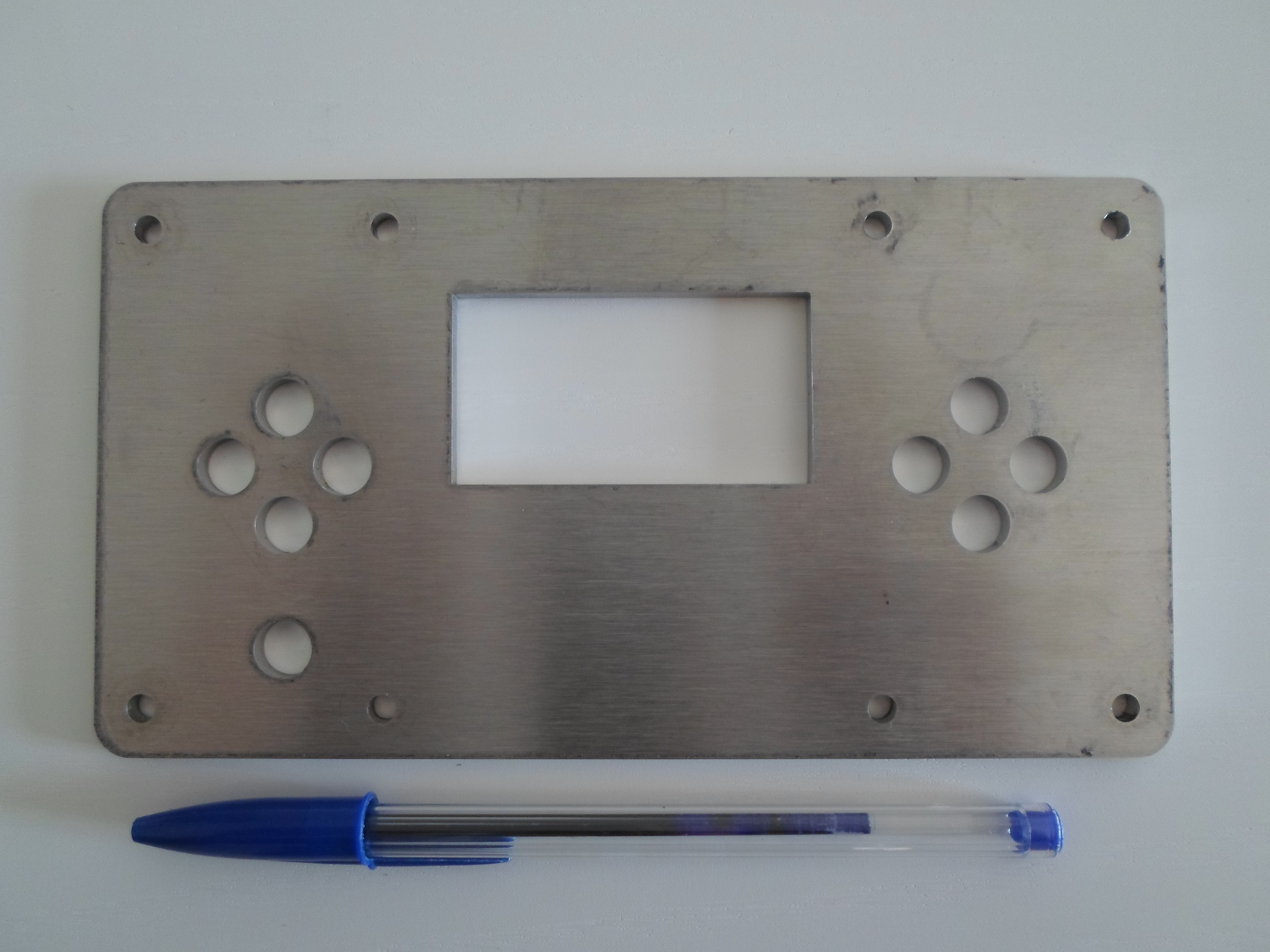
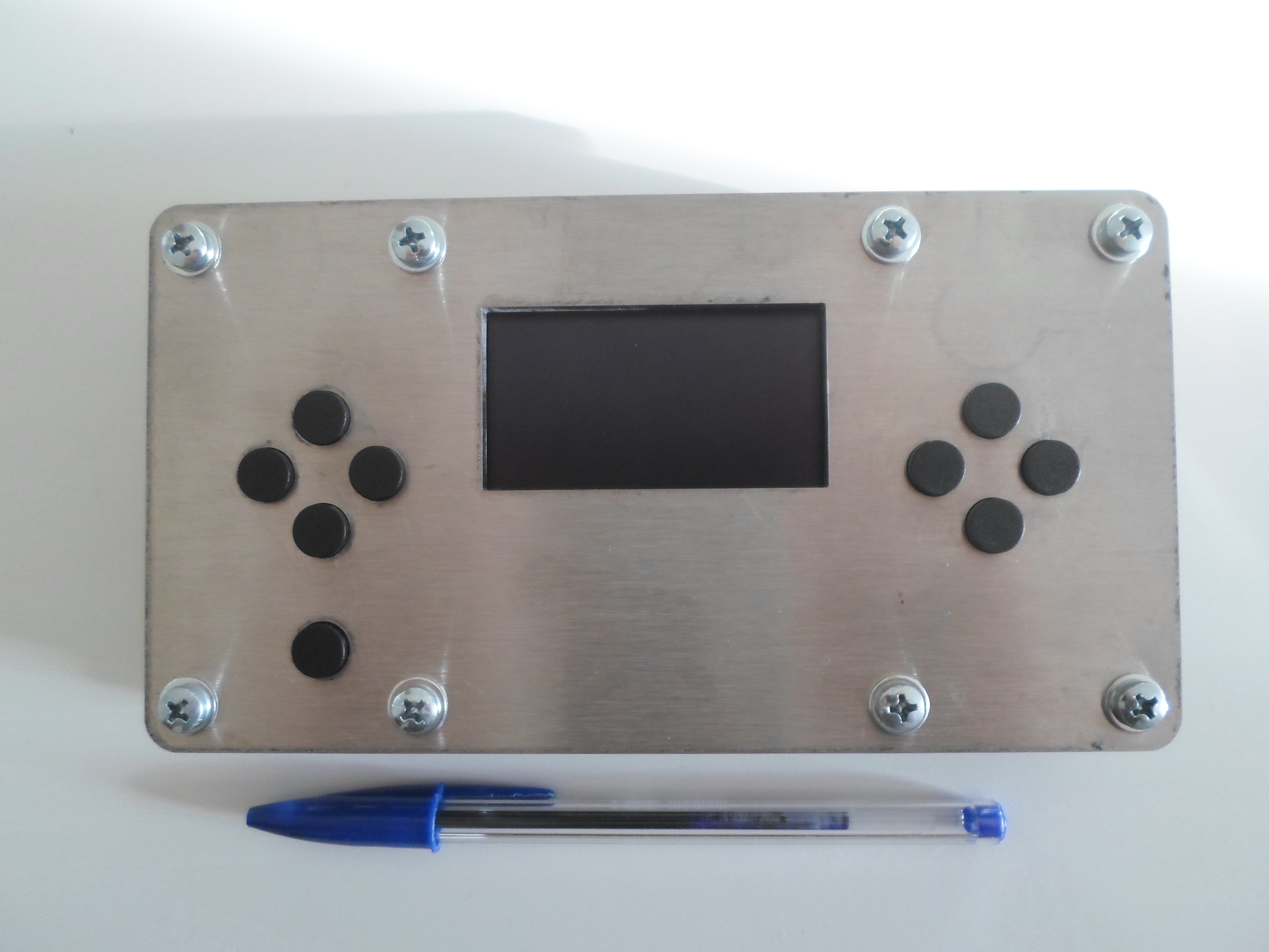
The casing is made of two laser-cut metal plates. They are both 4 mm thick and made of stainless 304 steel.
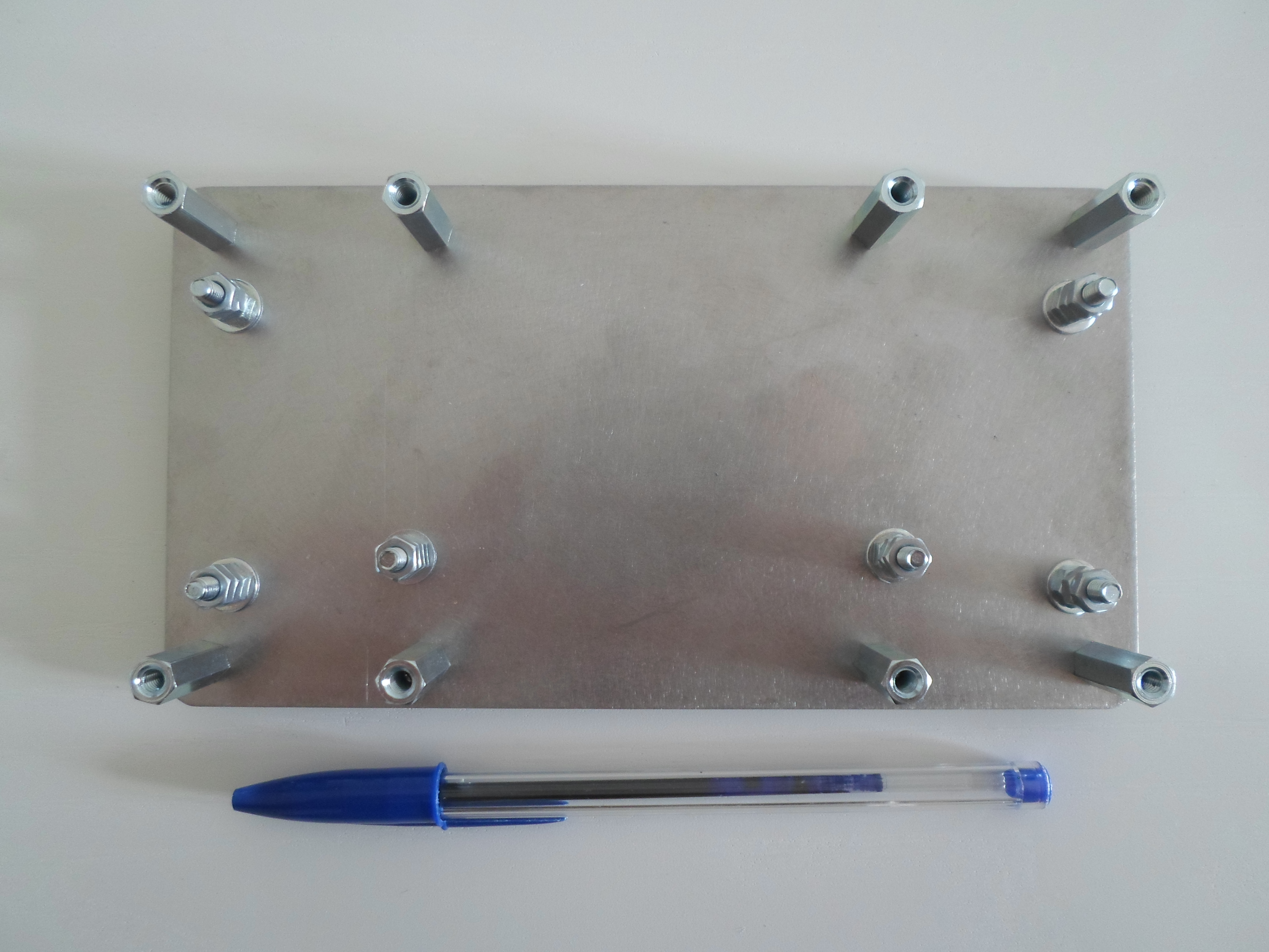
The metal spacers are 20 mm high. The reference used here is 970200471 from Würth Elektronik.
Casing plates :
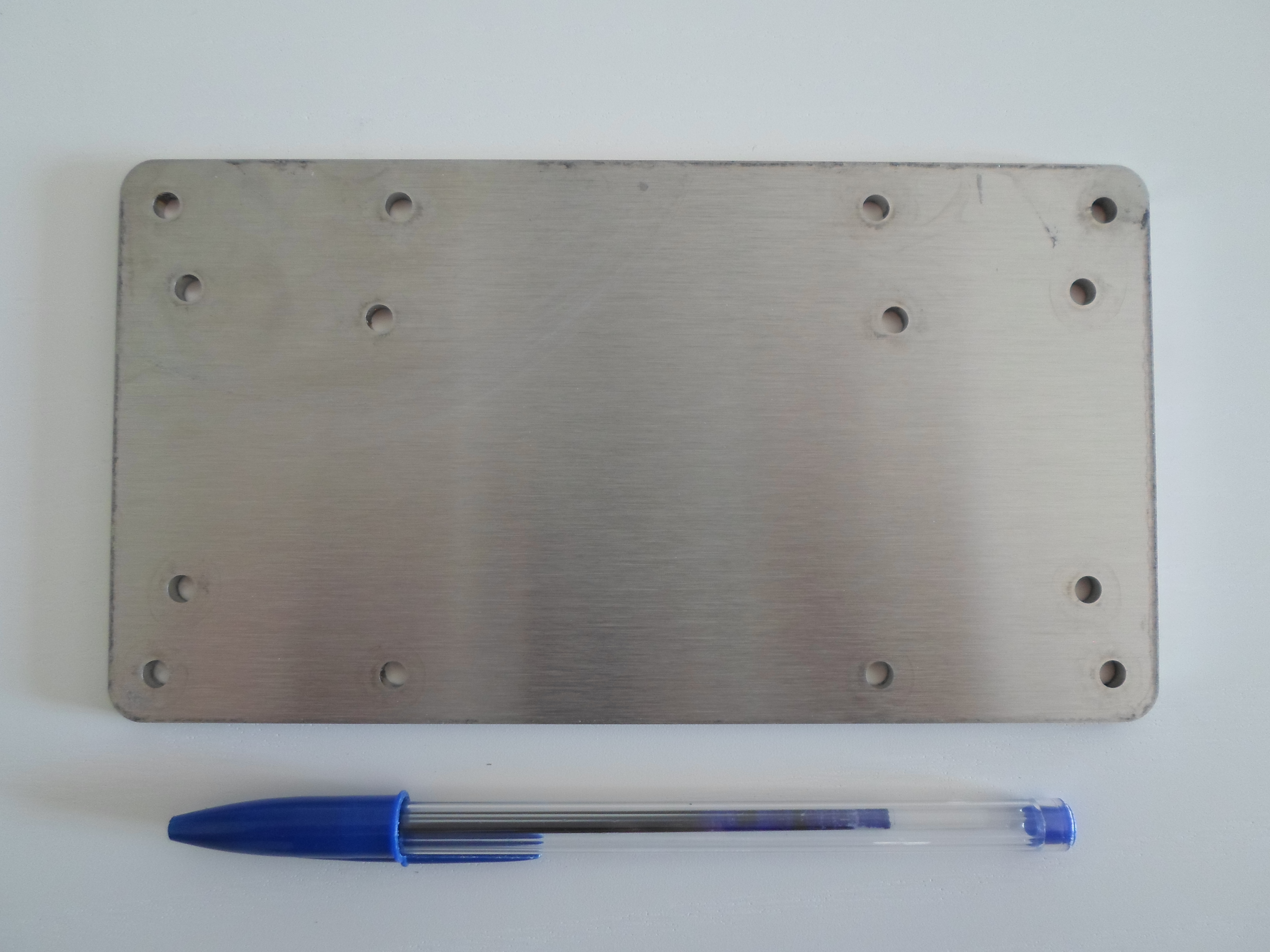
Bottom plate with screws :
Bottom plate with screwed PCB :
Fully assembled console :
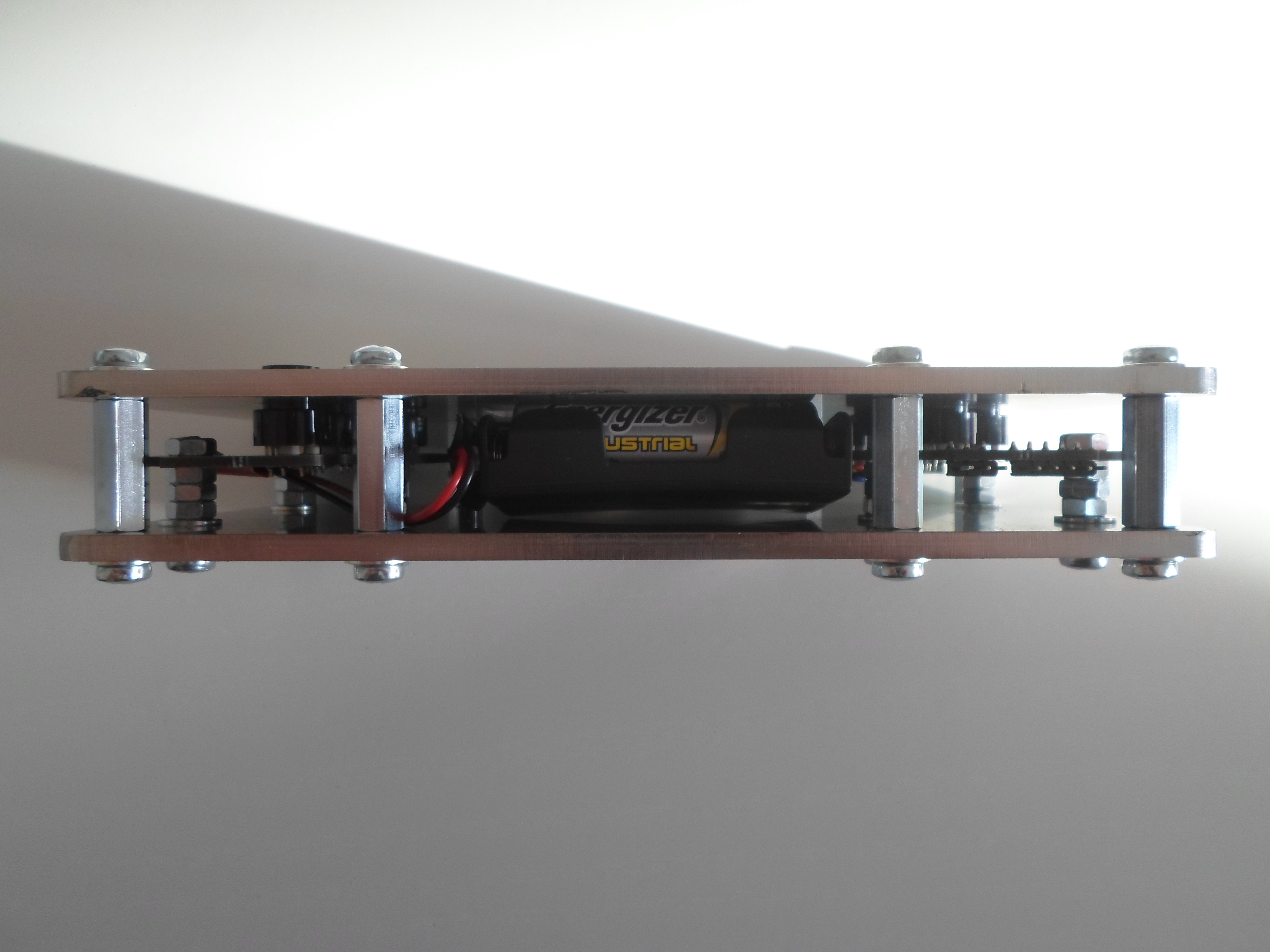
The hatch is made of PCB FR4. The hatch does not require to be as strong as the console casing and the FR4 is a good material to cut complex shapes into.
The hatch is cut as a PCB panel containing all the required parts :
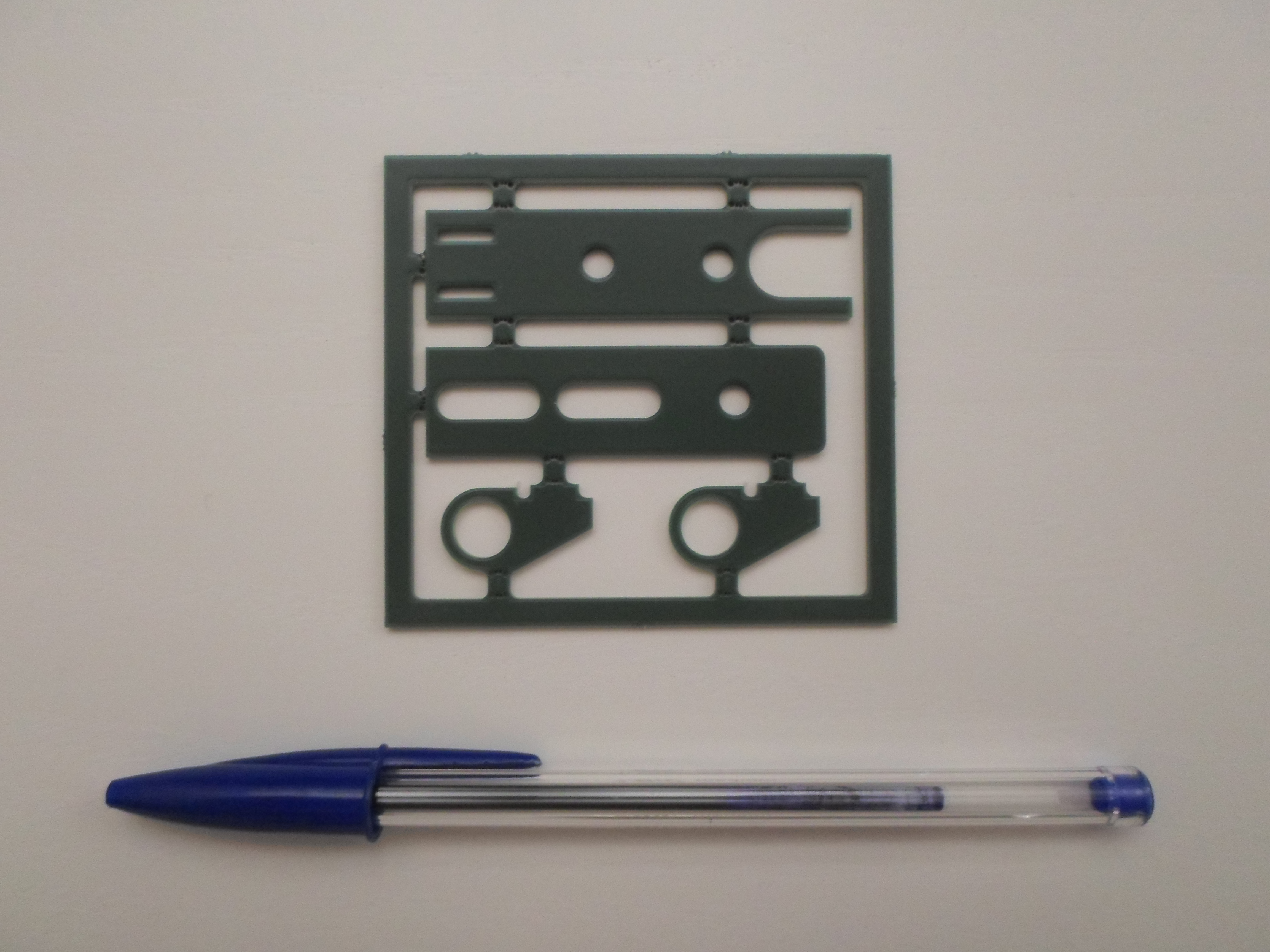
The first assembly step is to glue the hinges :
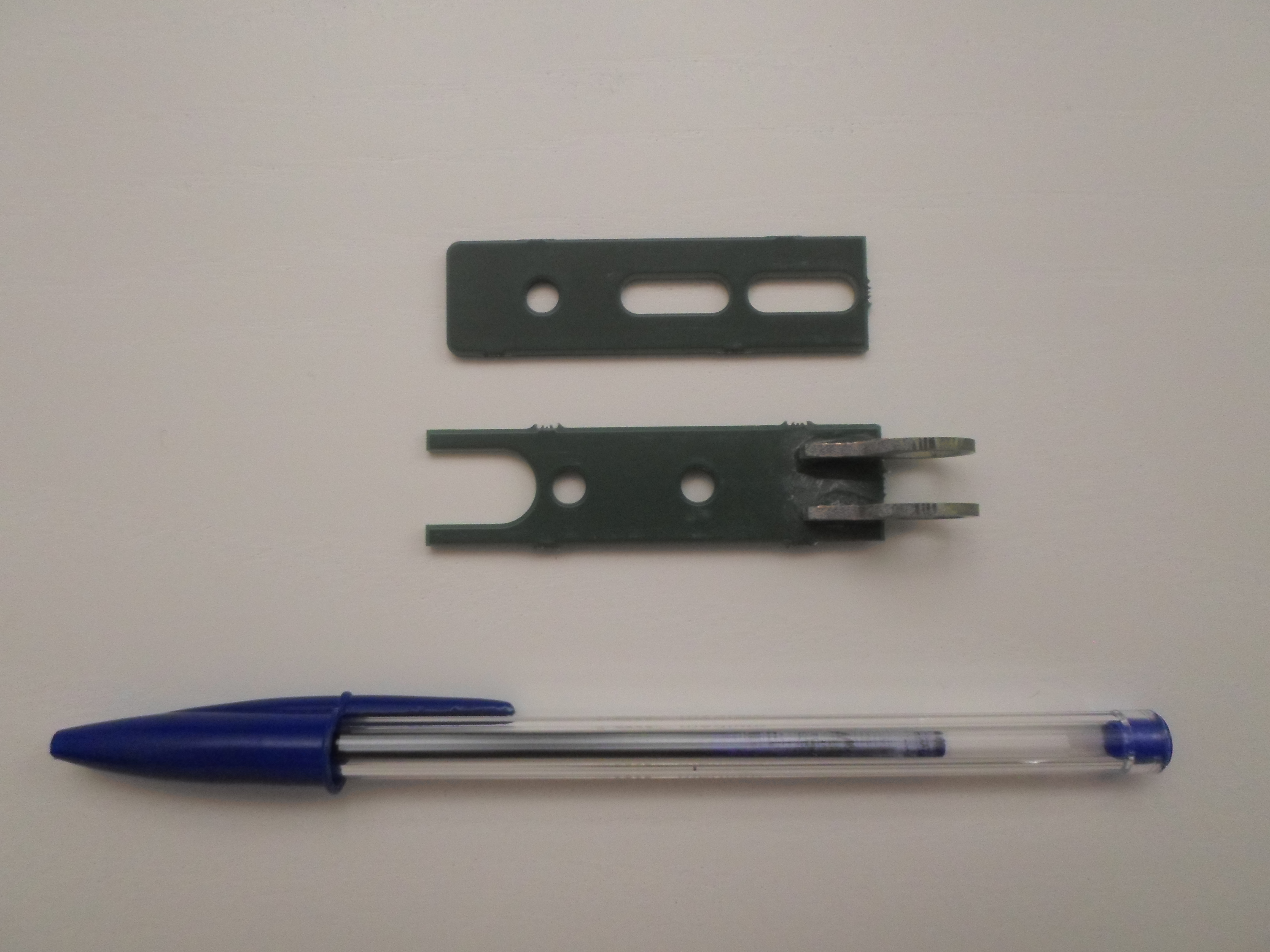
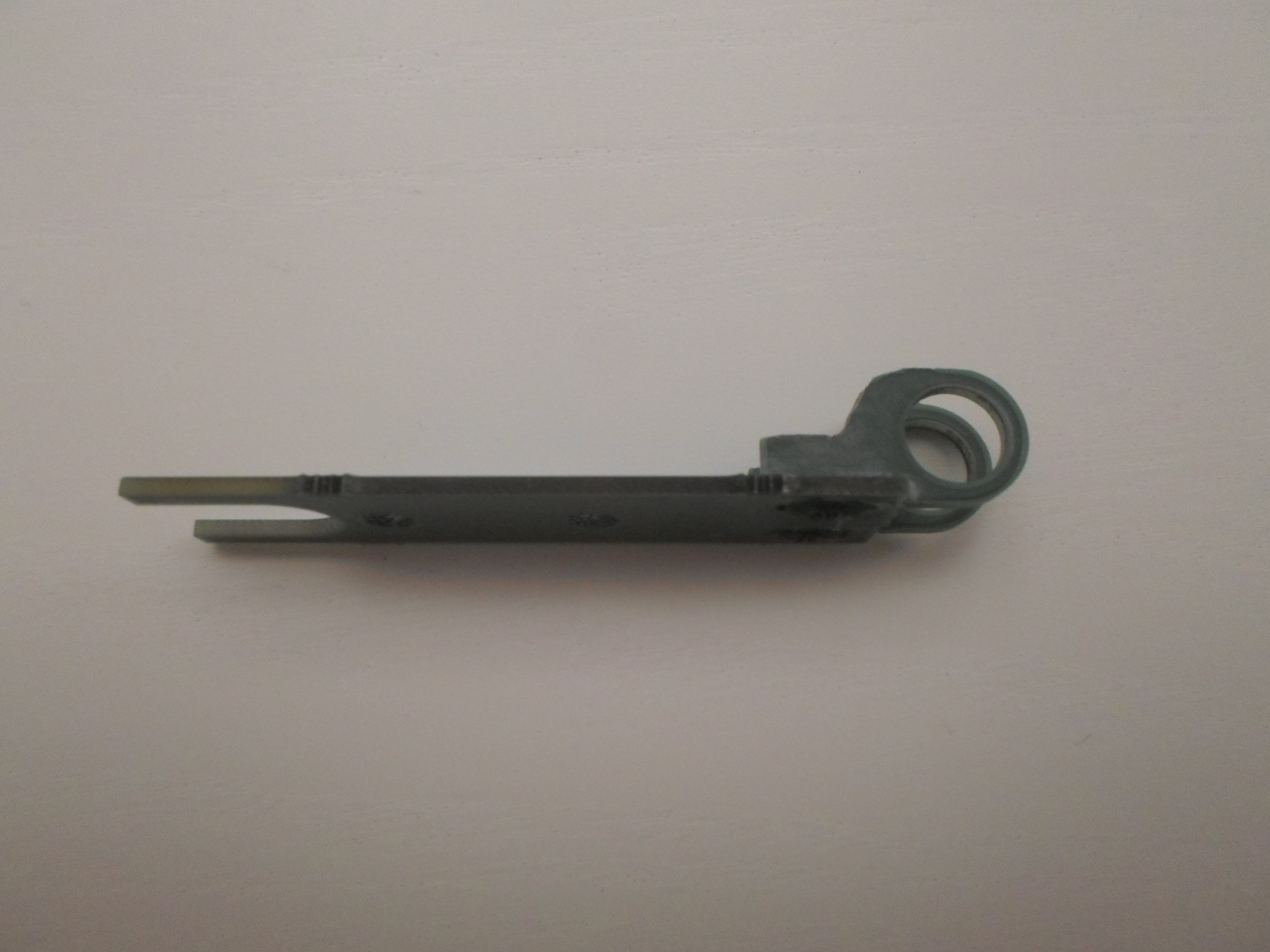
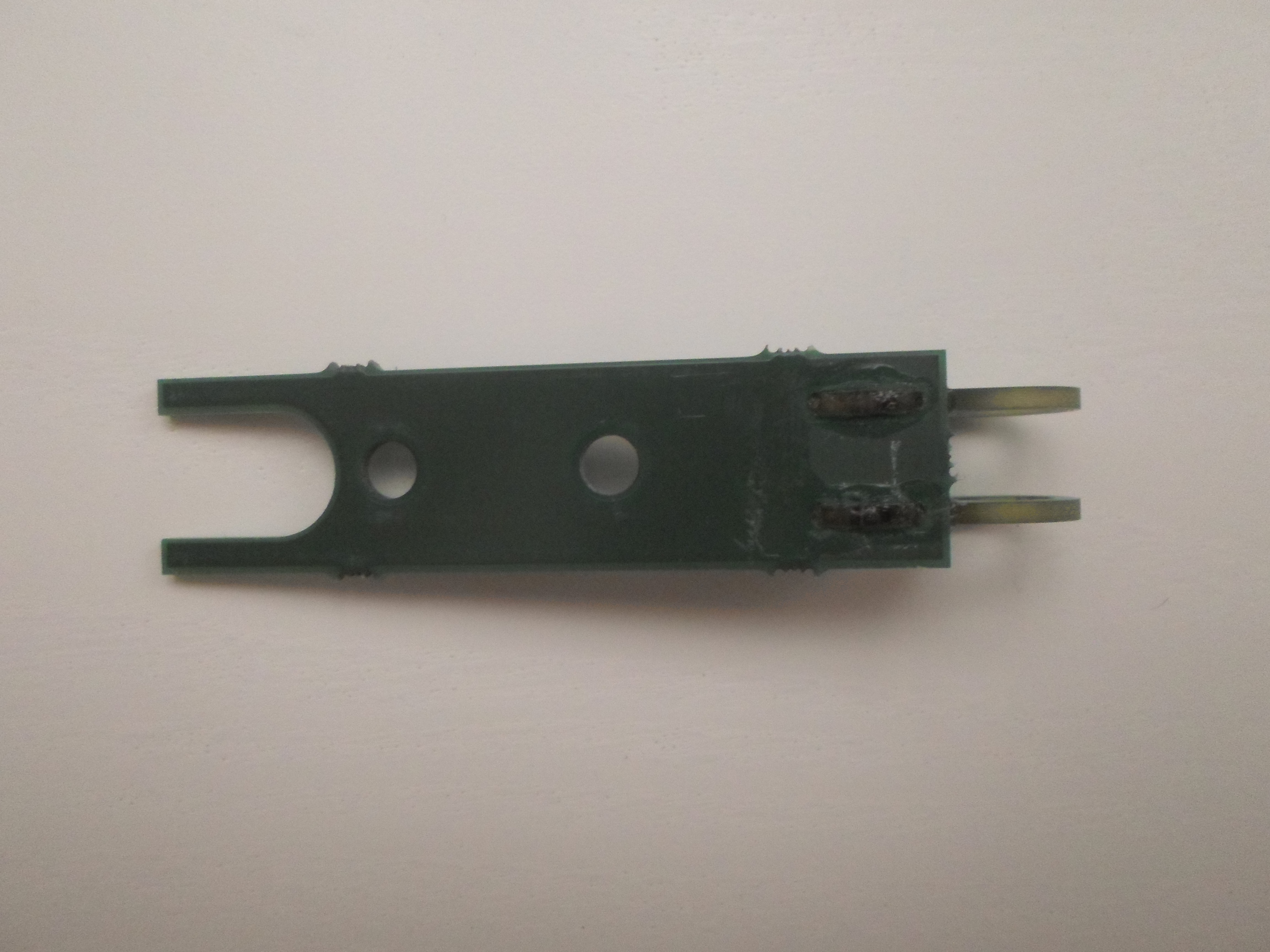
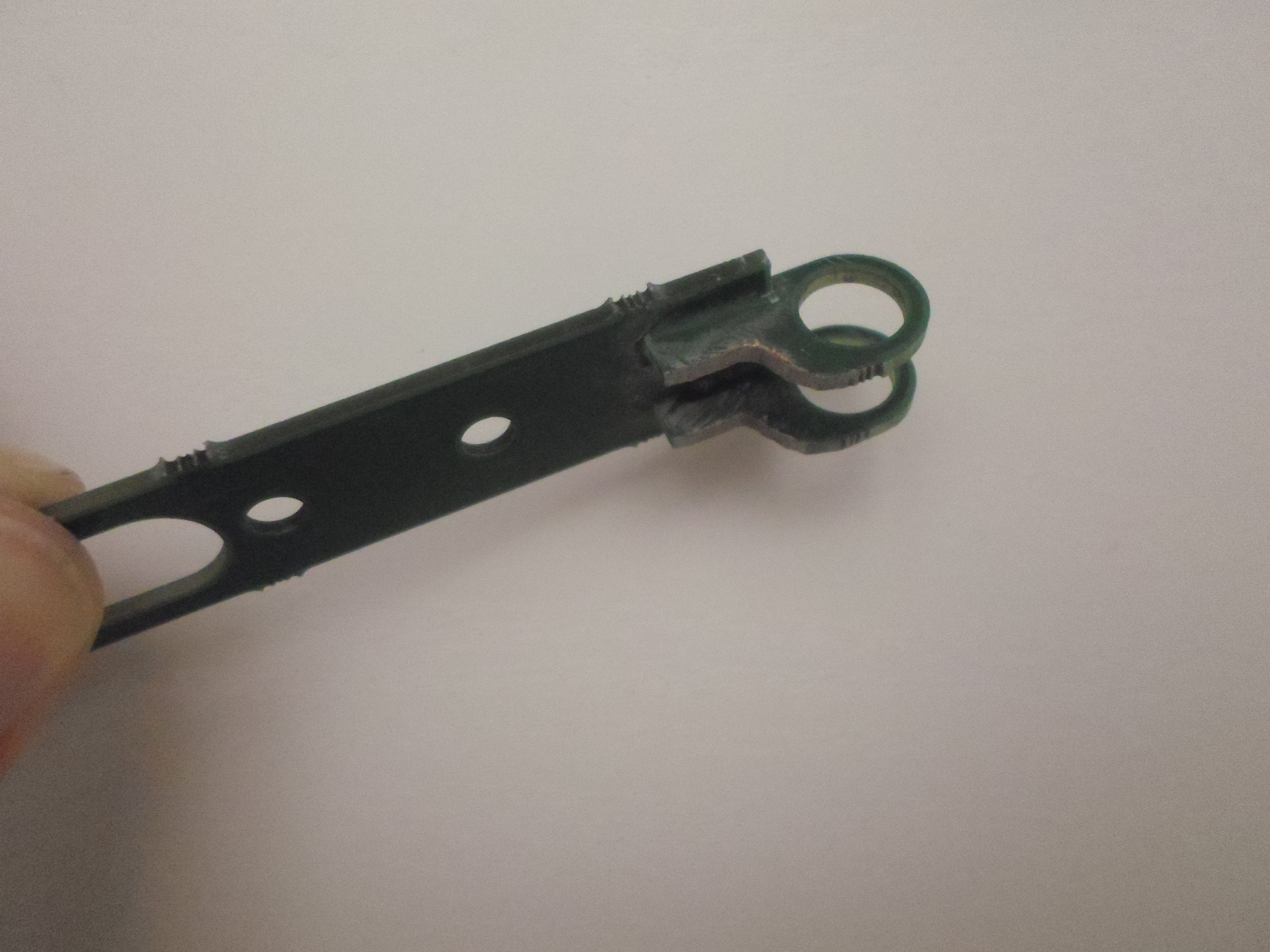
The second step is to screw the sliding part, and also the bolt used to manipulate the hatch slider :
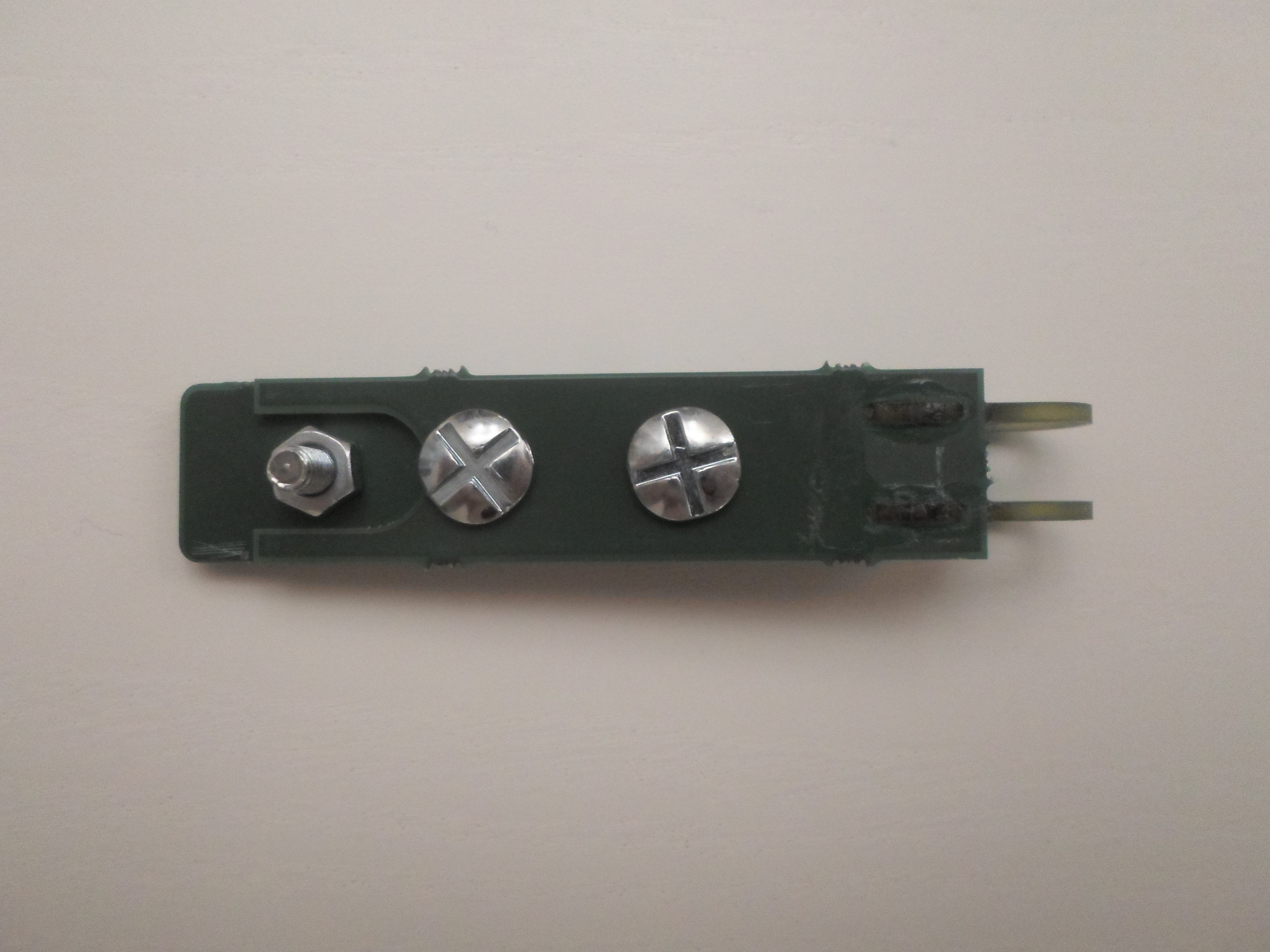
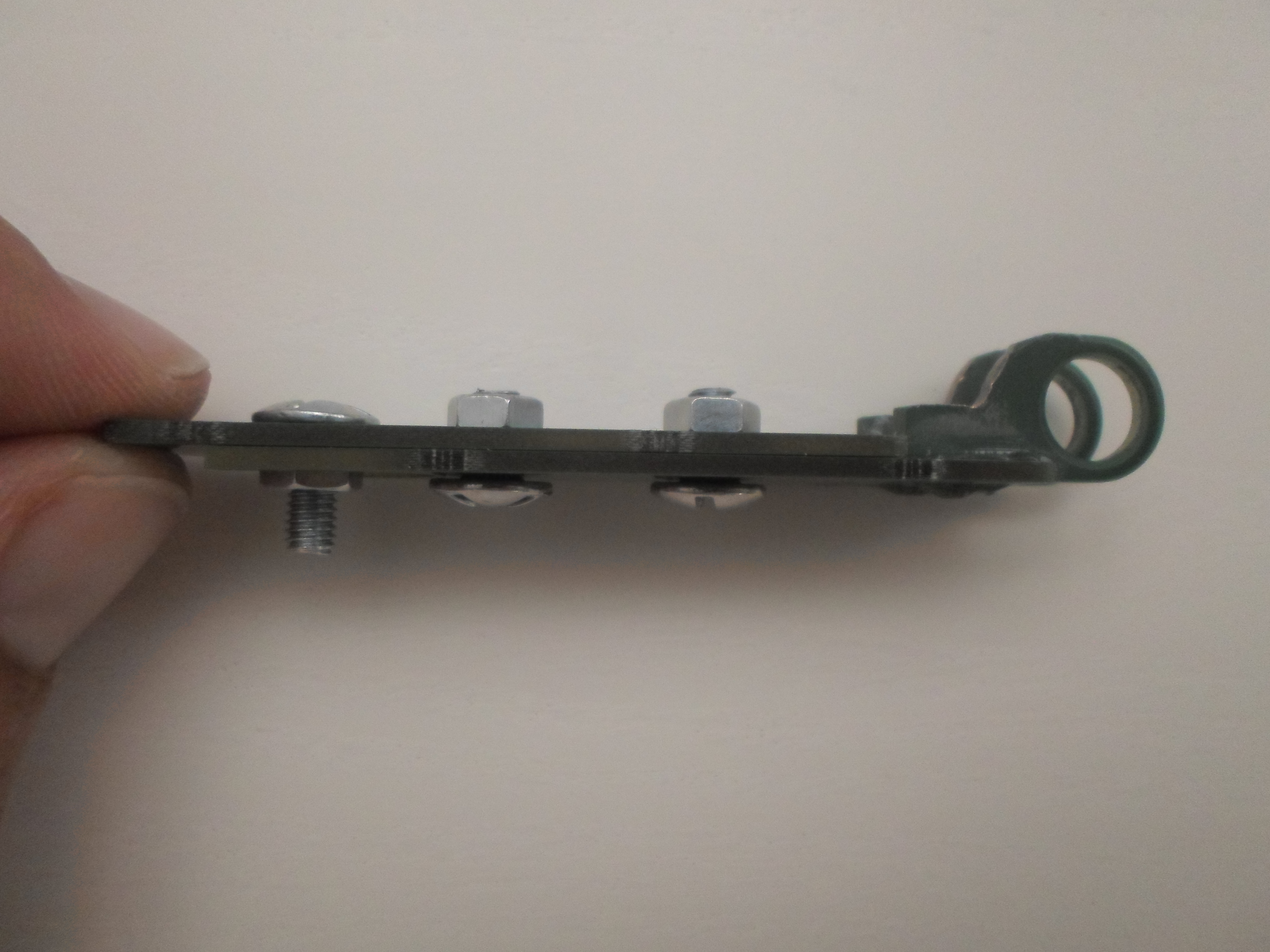
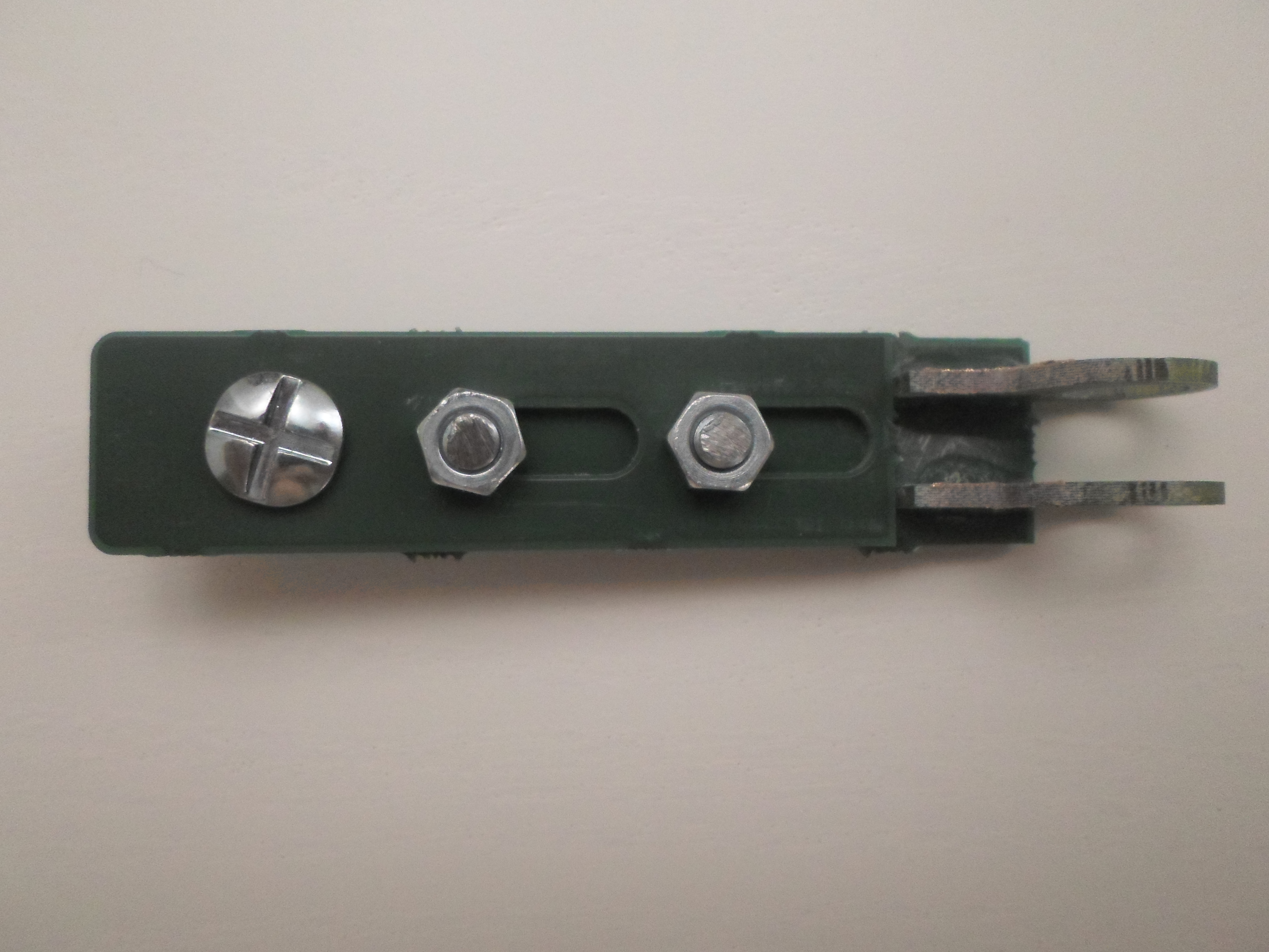
There is not enough room to use Nyloc nuts, so normal nuts are used and held in place with threadlocker.
The tightening of these bolts allows the slider to slide with a little force, so the hatch can't open alone.
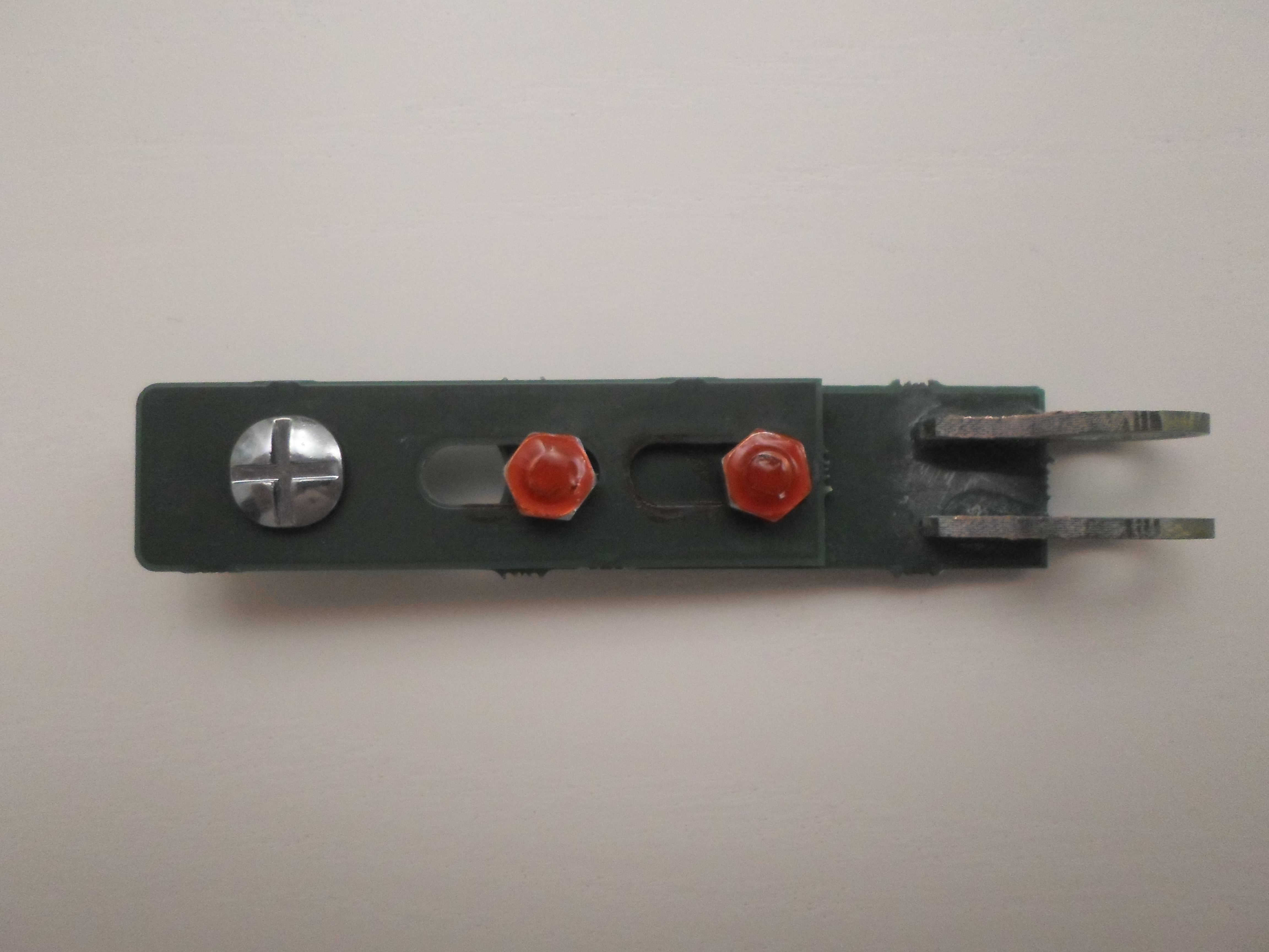
The strike is made of a piece of PCB coming from the panel edge that is inserted by force between the two metal plates :
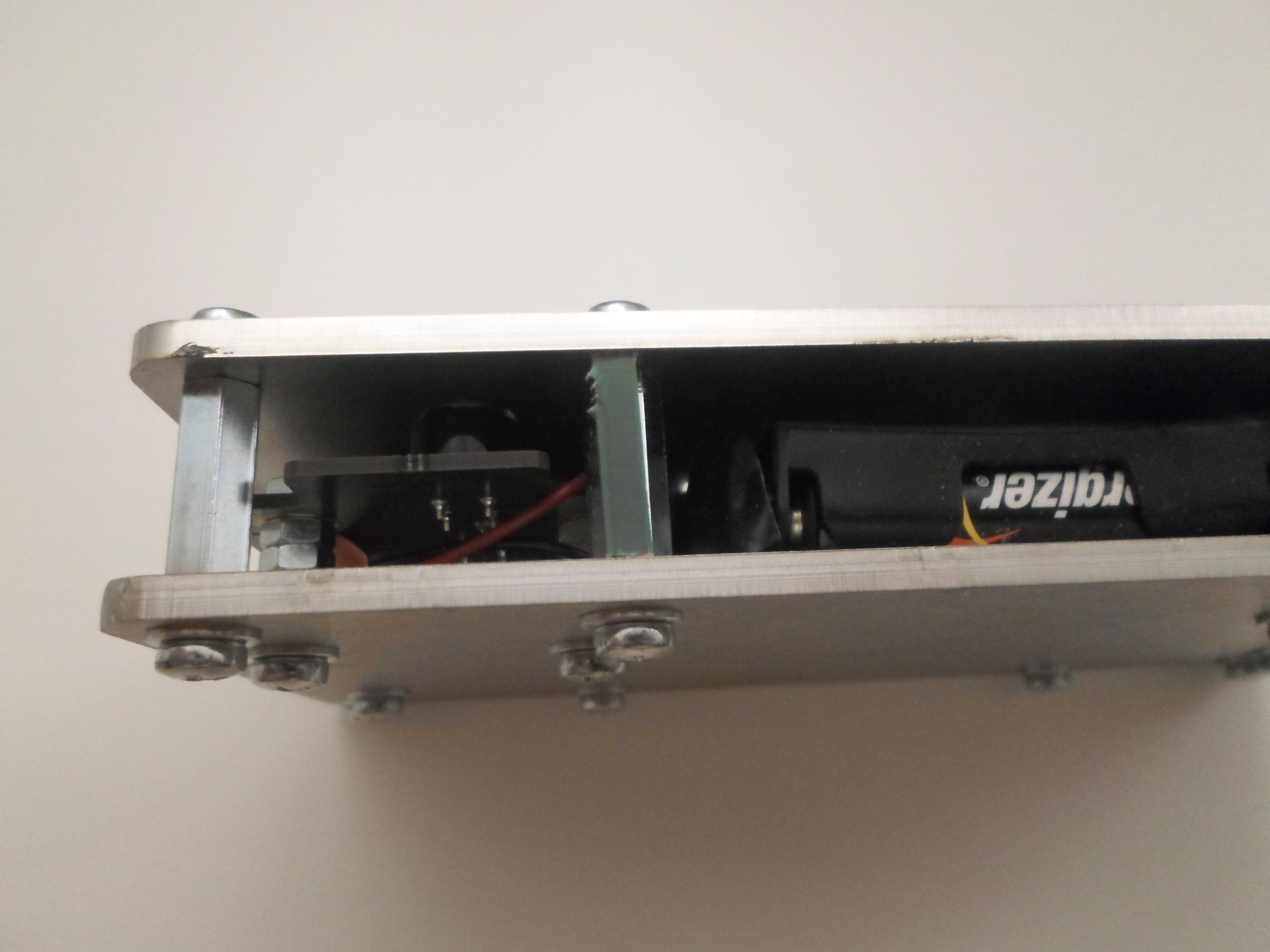
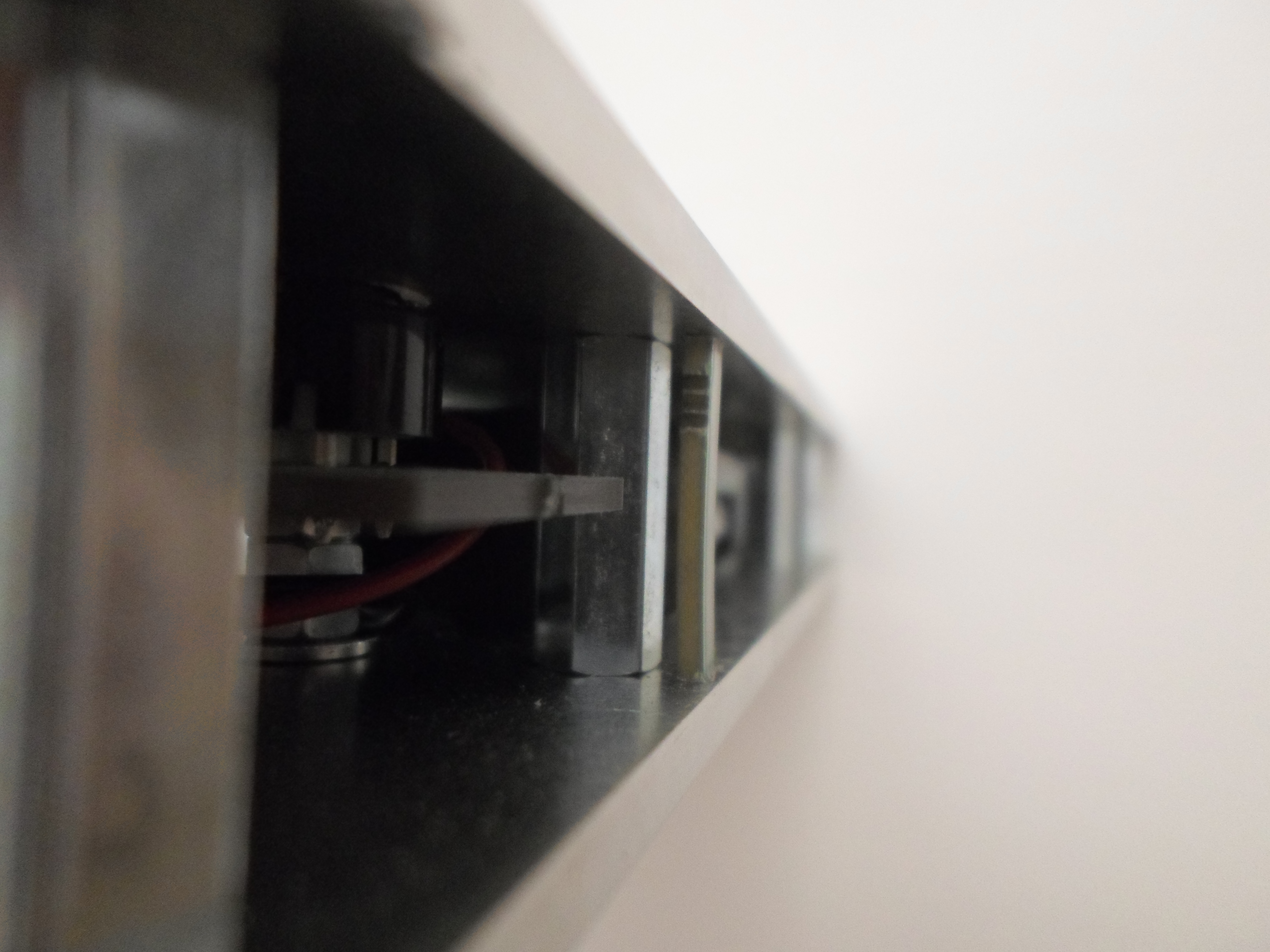
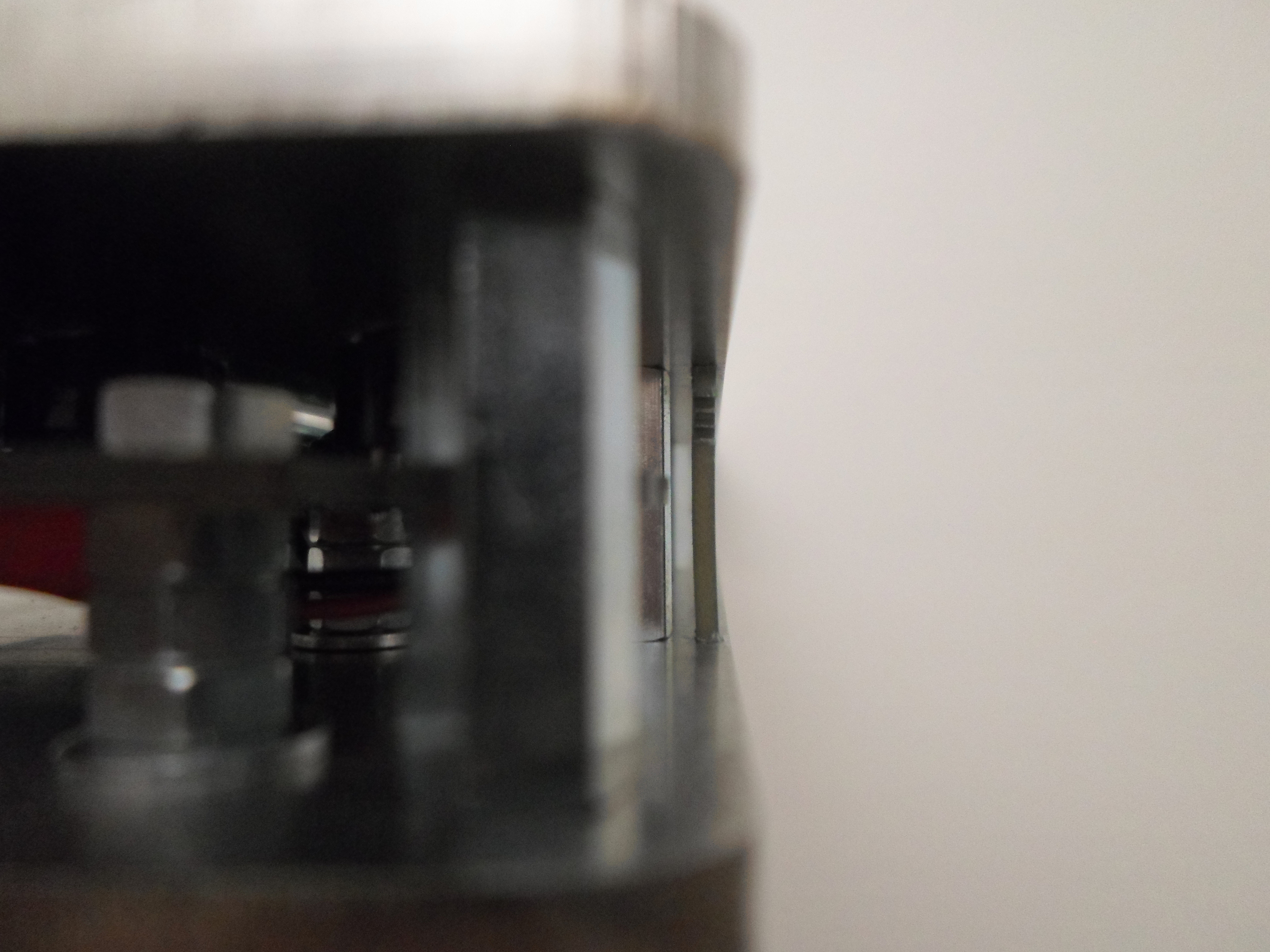
Now the hatch can be assembled onto the console.
Locked hatch :
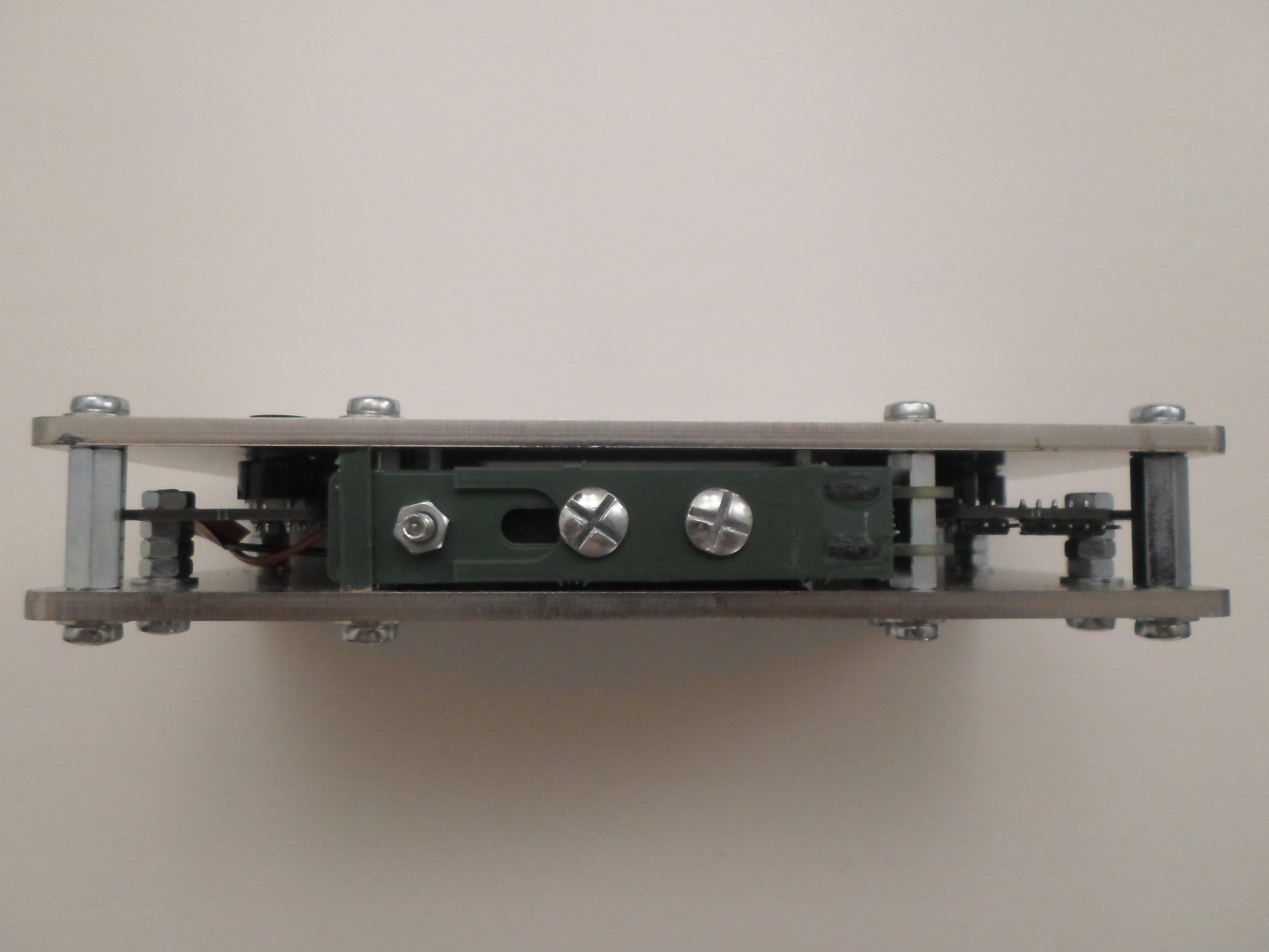
Unlocked hatch :
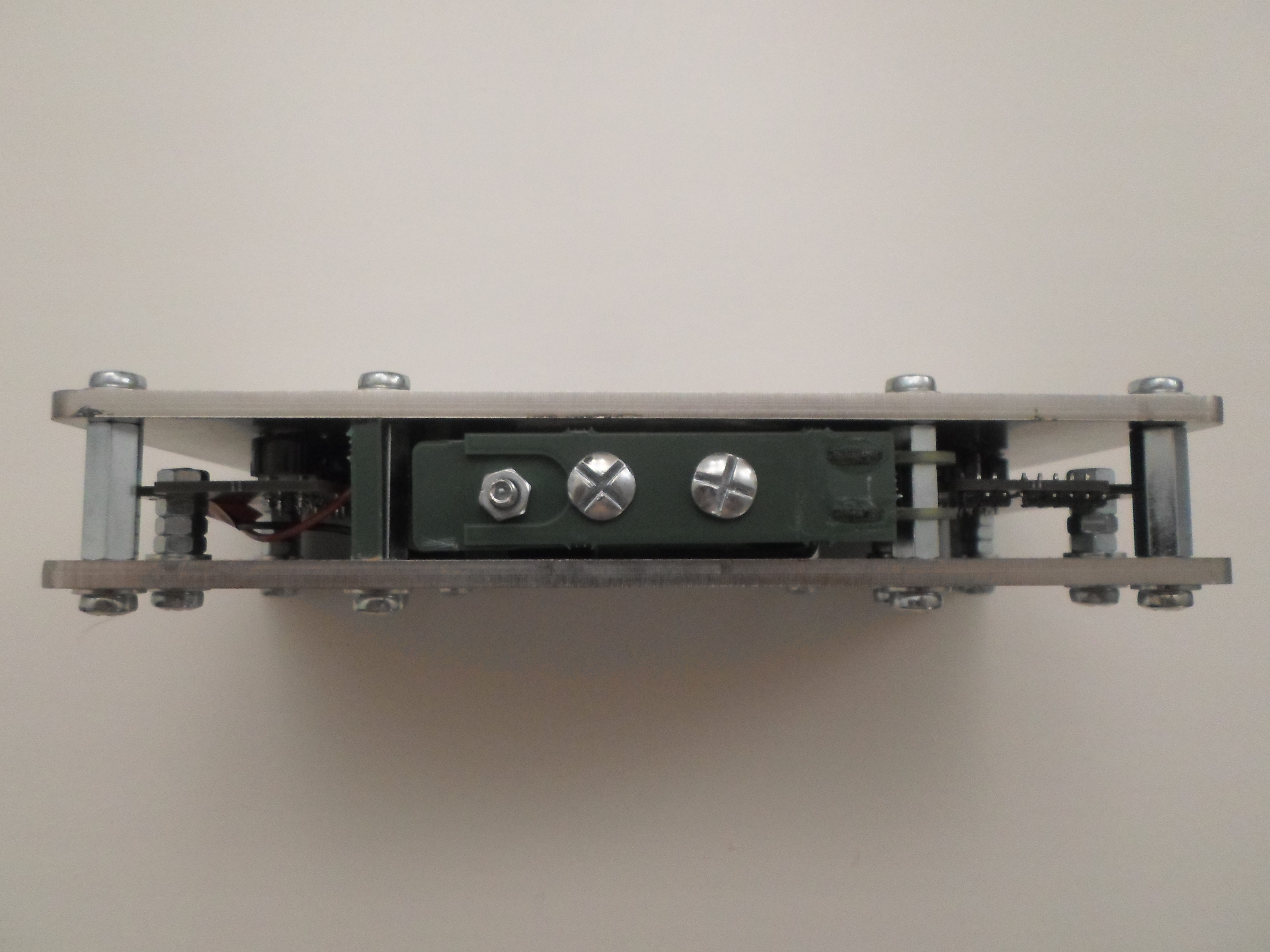
Opened hatch :
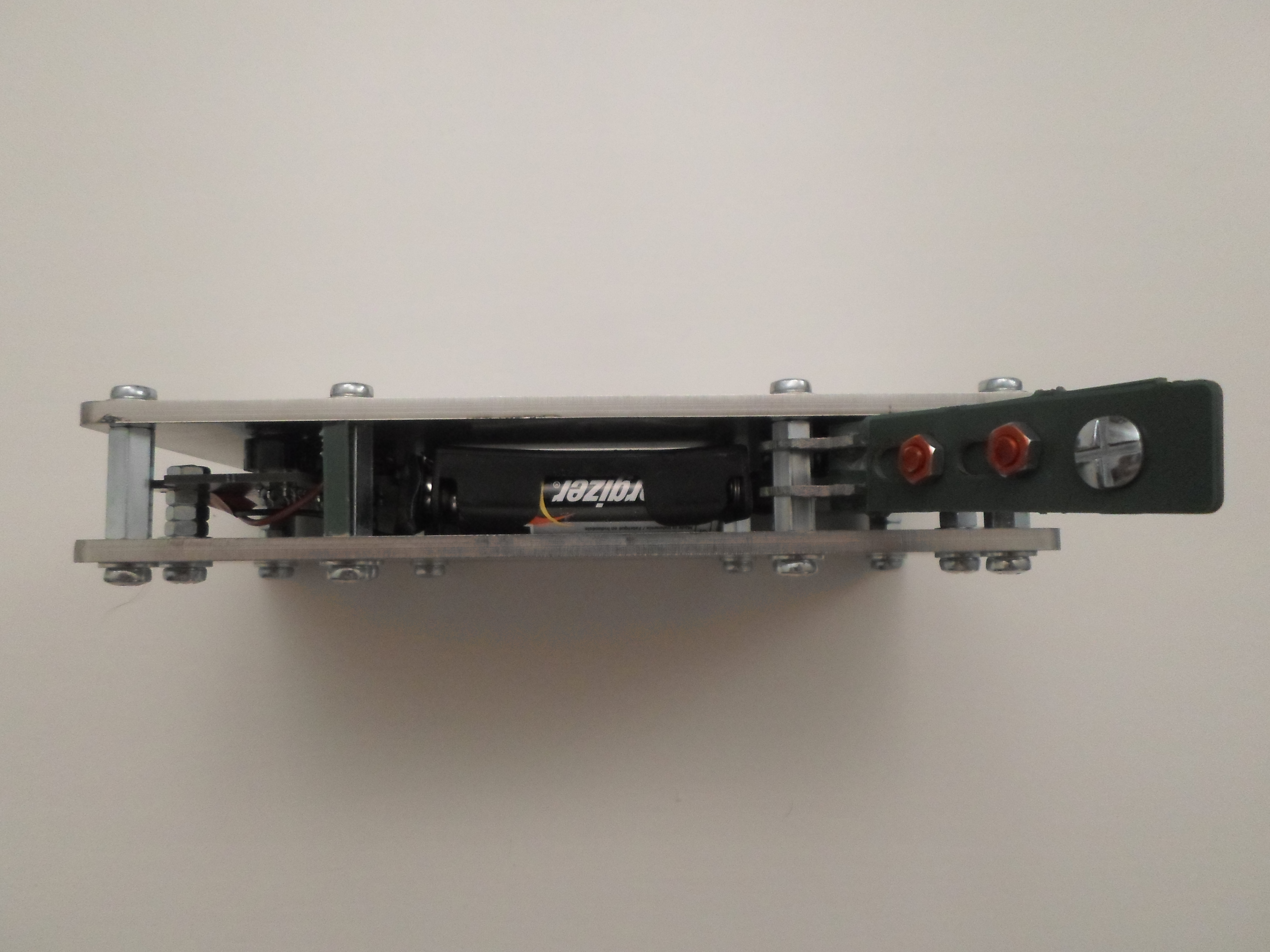
The console boot logo :
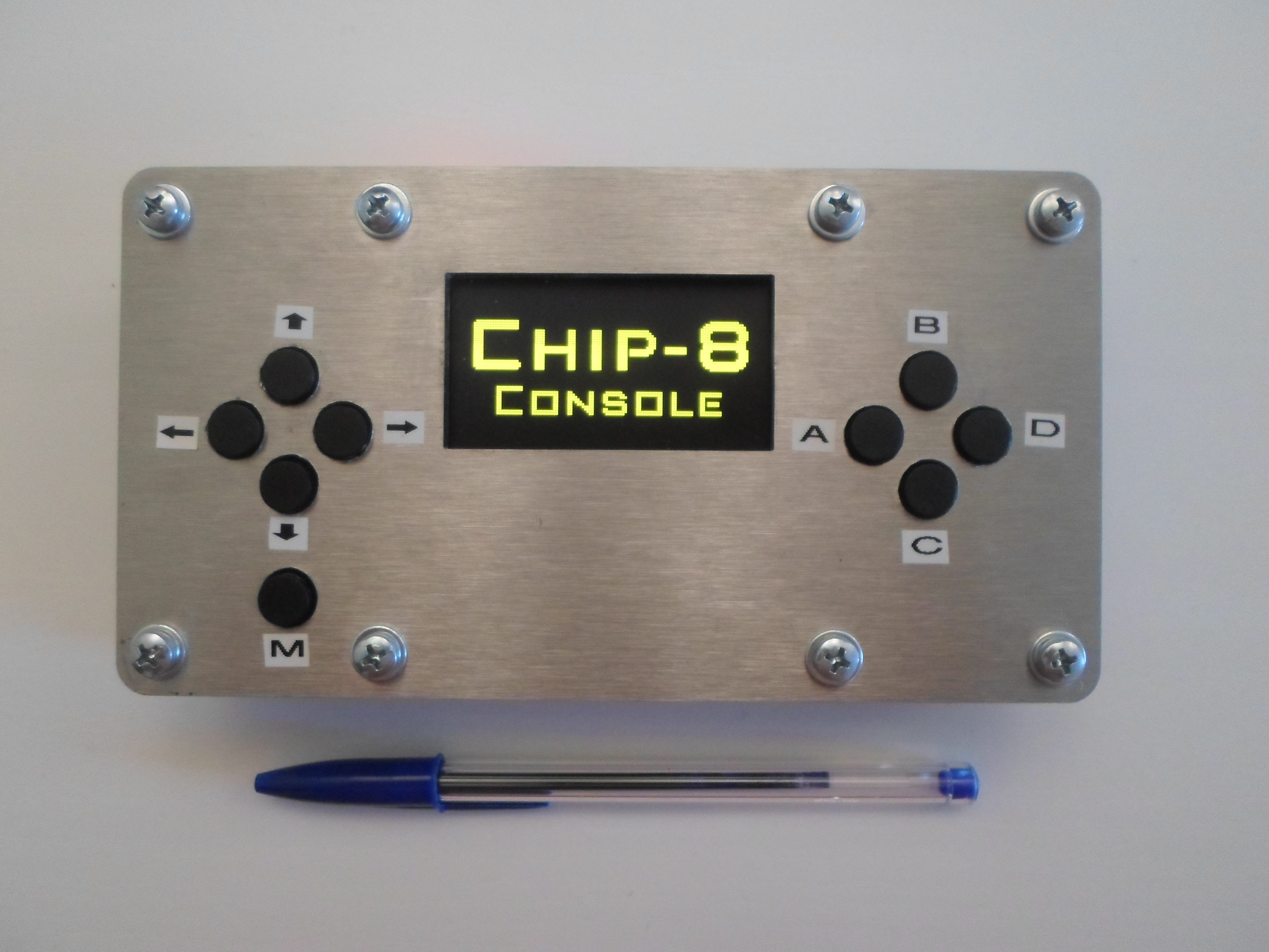
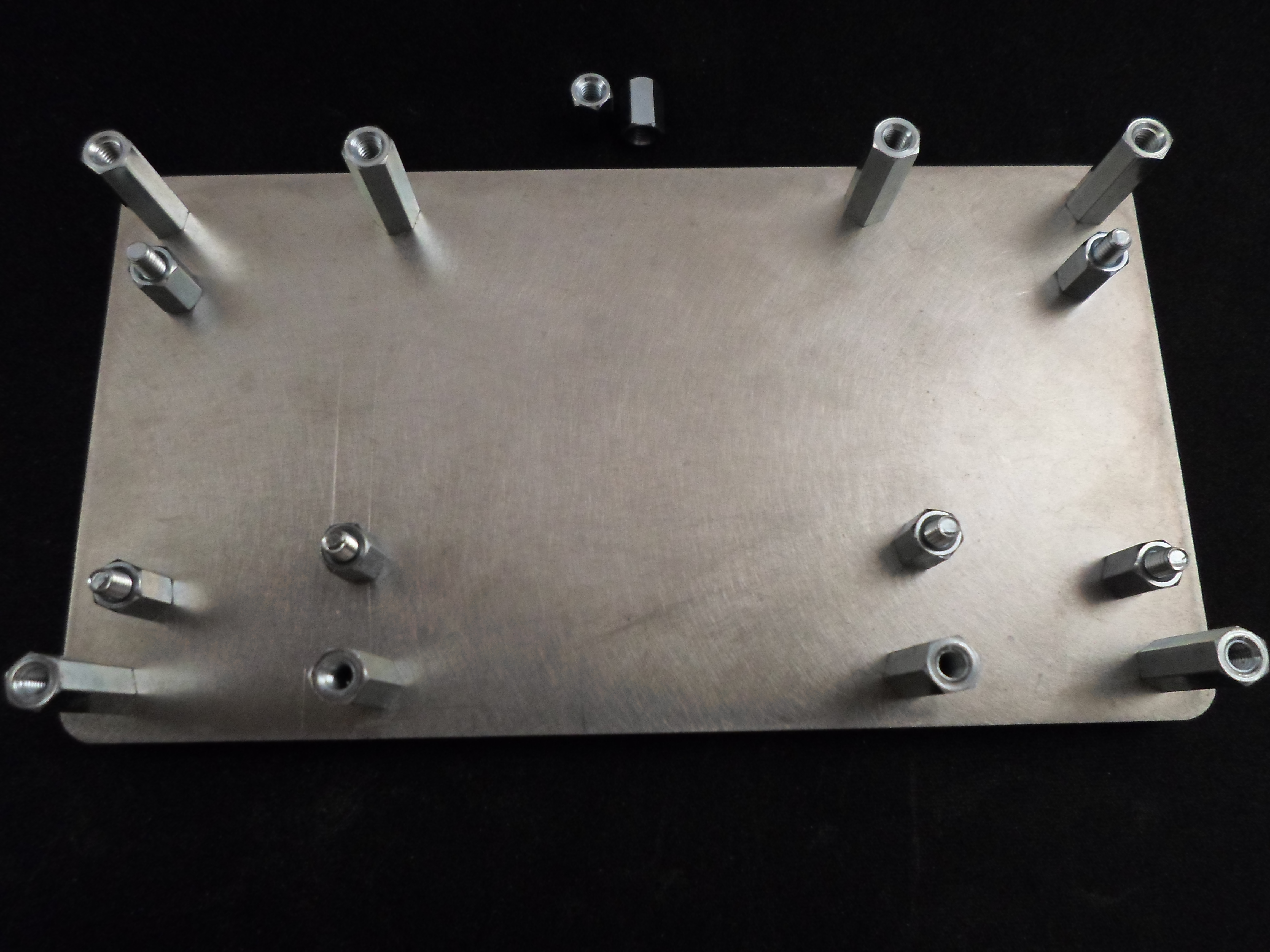
Improved the PCB supports that were made of several nuts. The nuts did not had the same width, resulting in the PCB not being perfectly flat. The nuts have then been replaced by precise 10mm spacers :
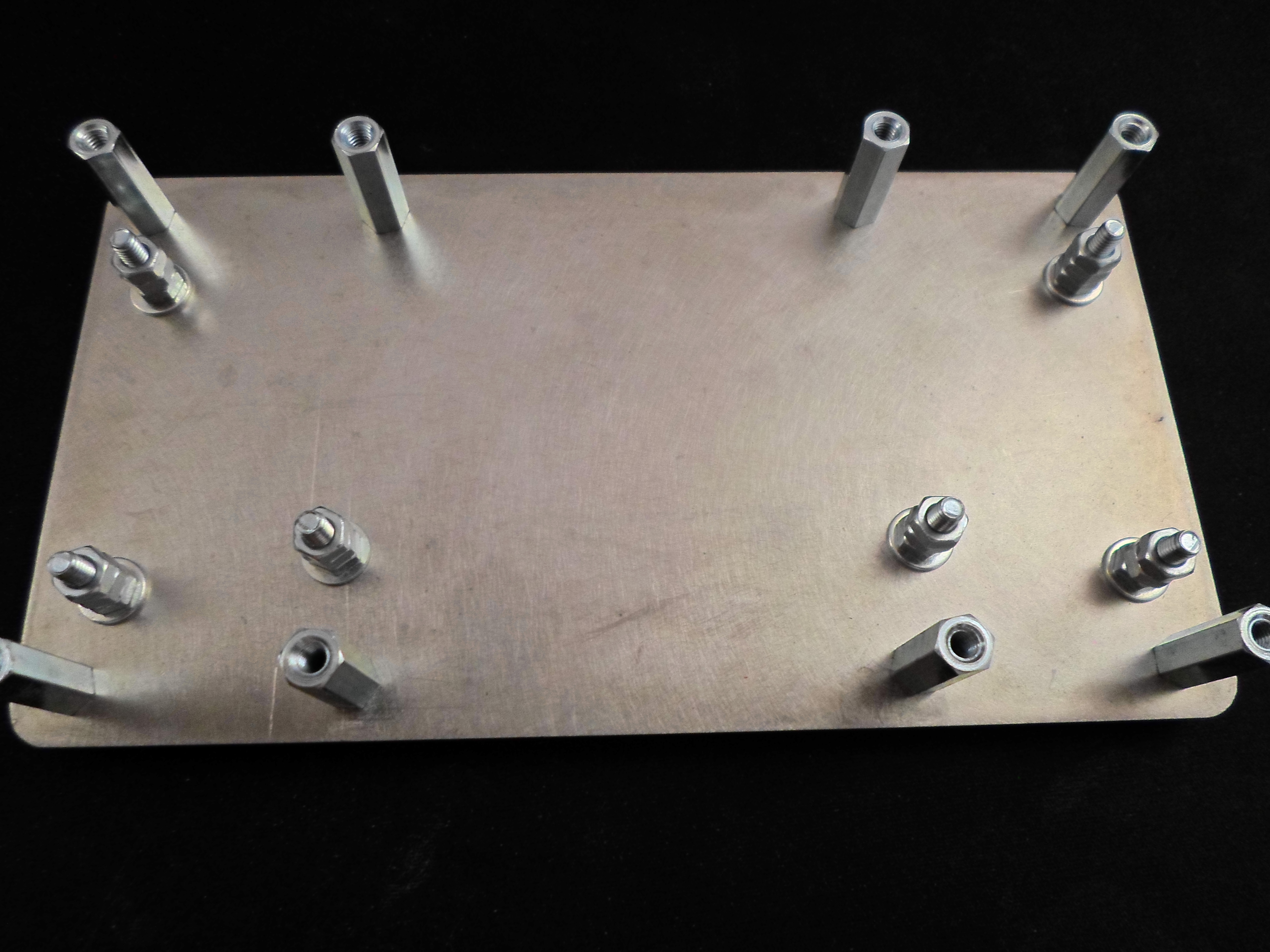
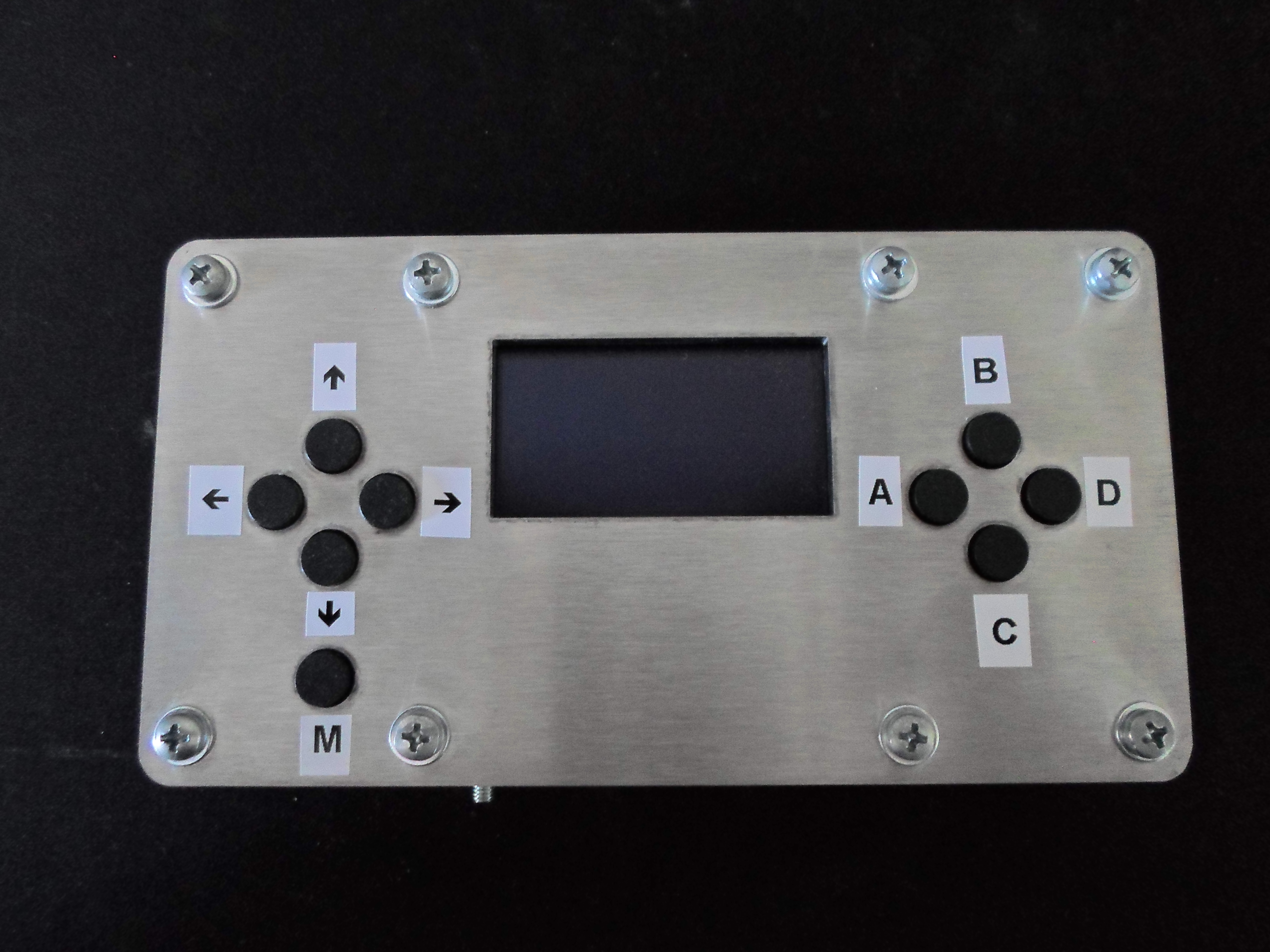
Improved the top plate button holes (using holes of 9.6mm diameter) :
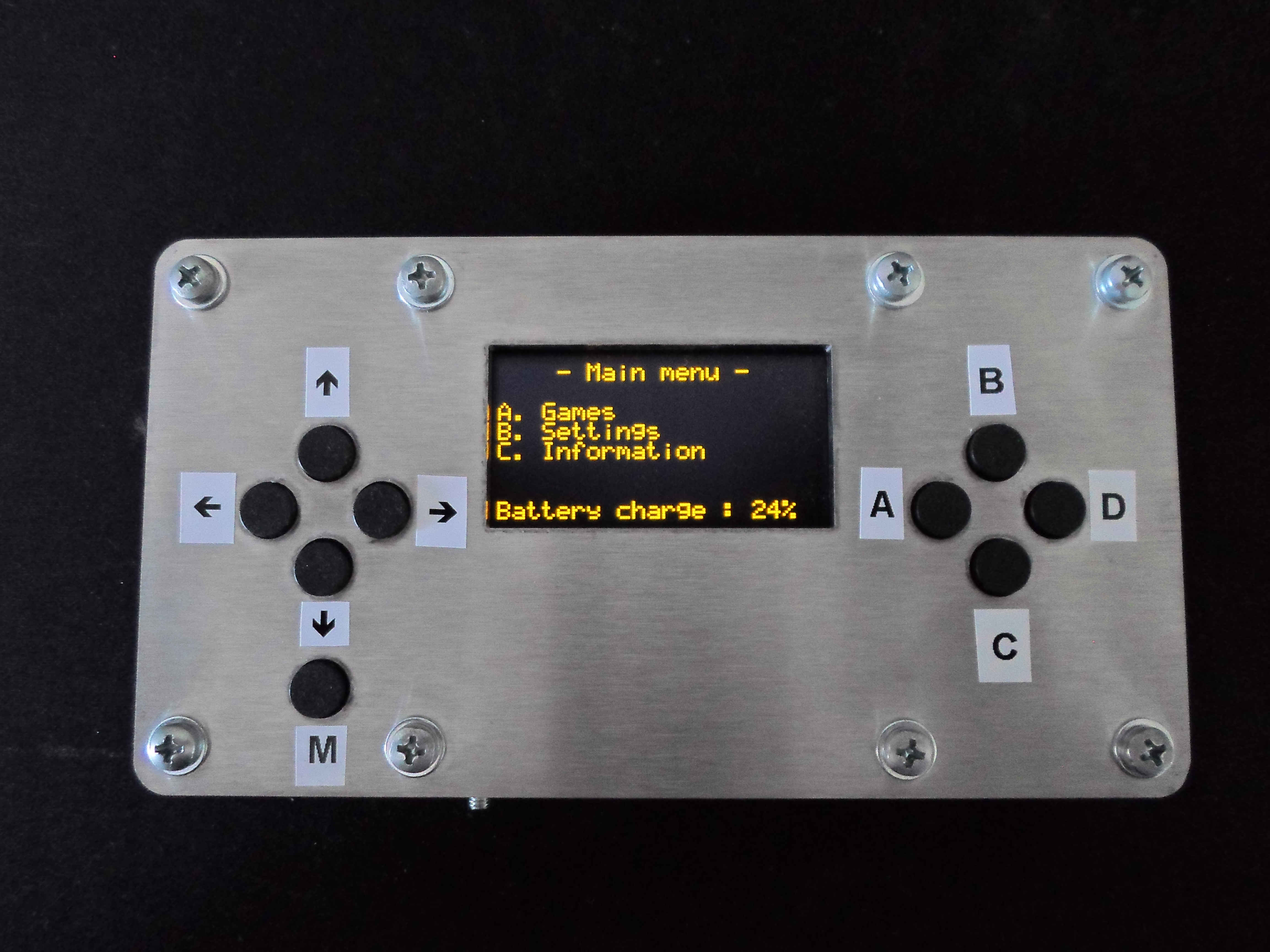
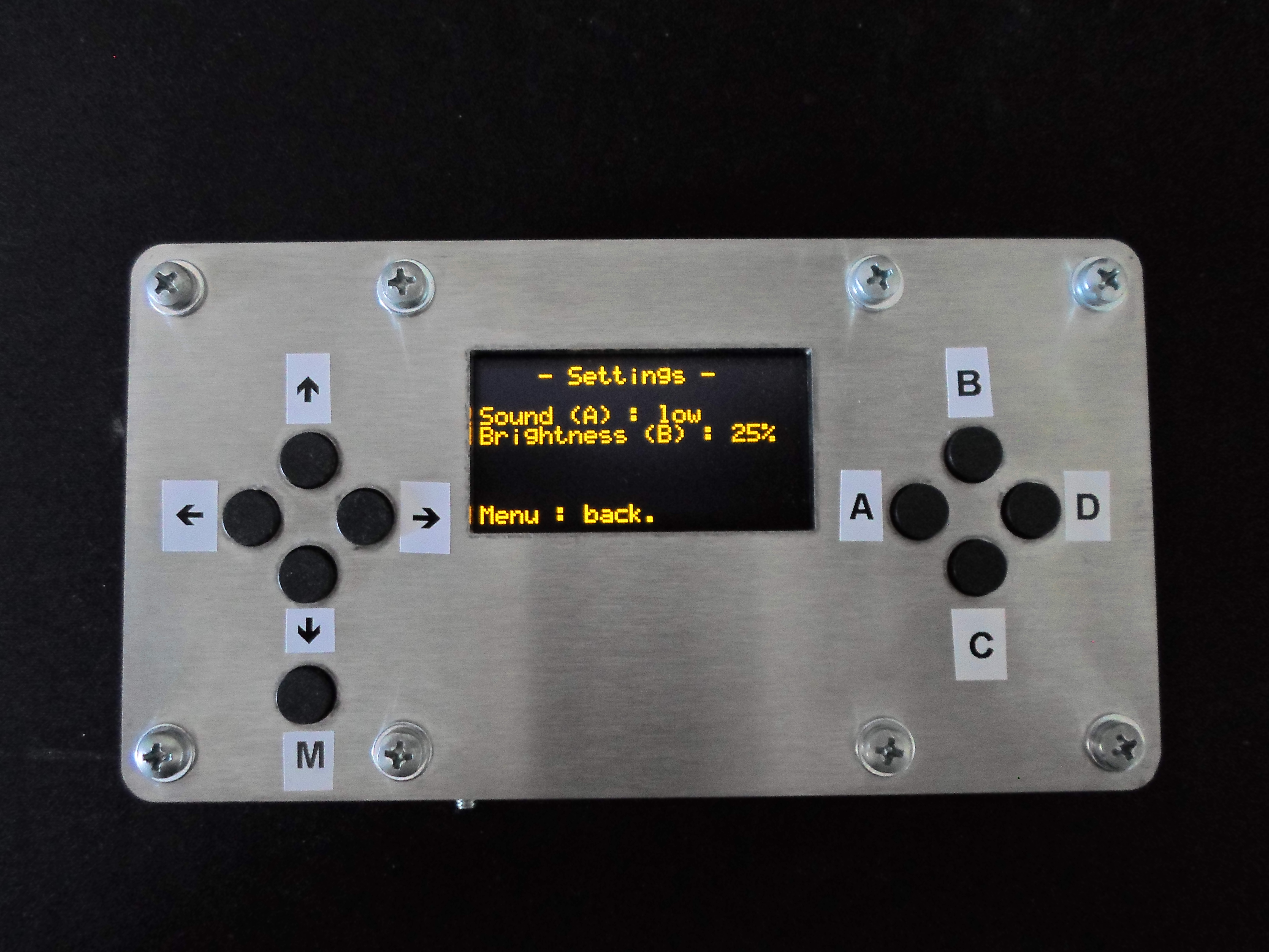
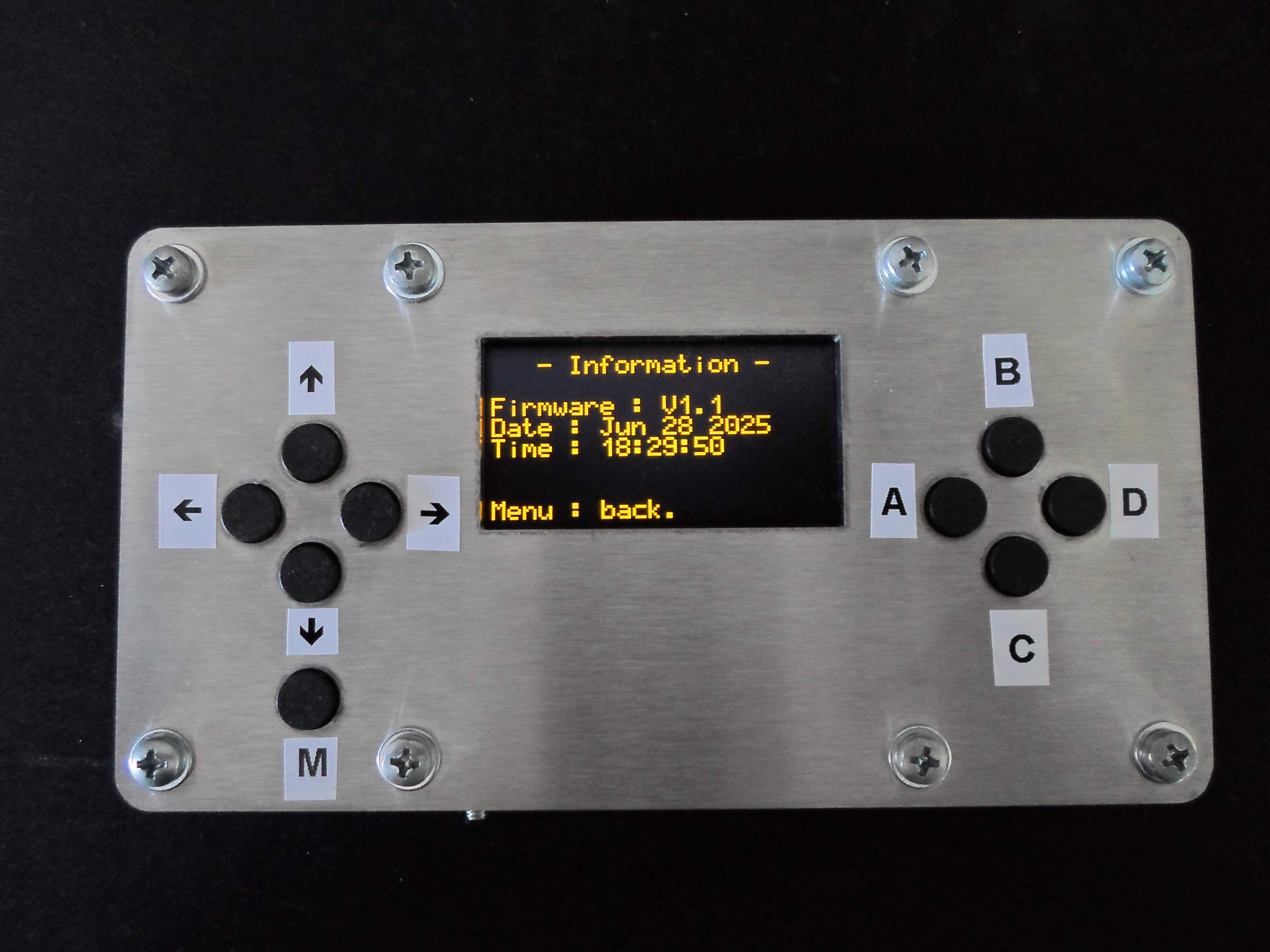
The various console menus (as of firmware V1.1) :
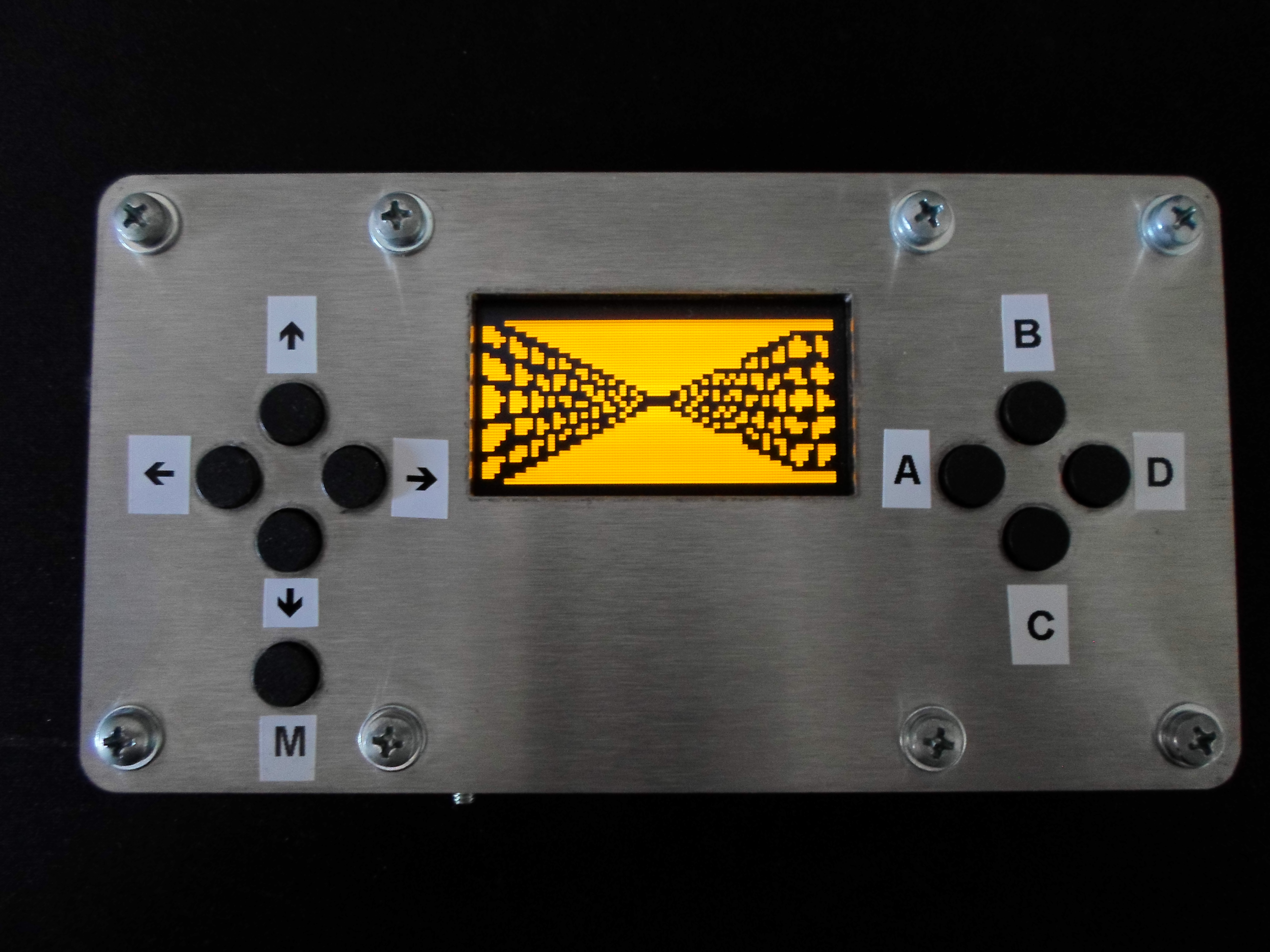
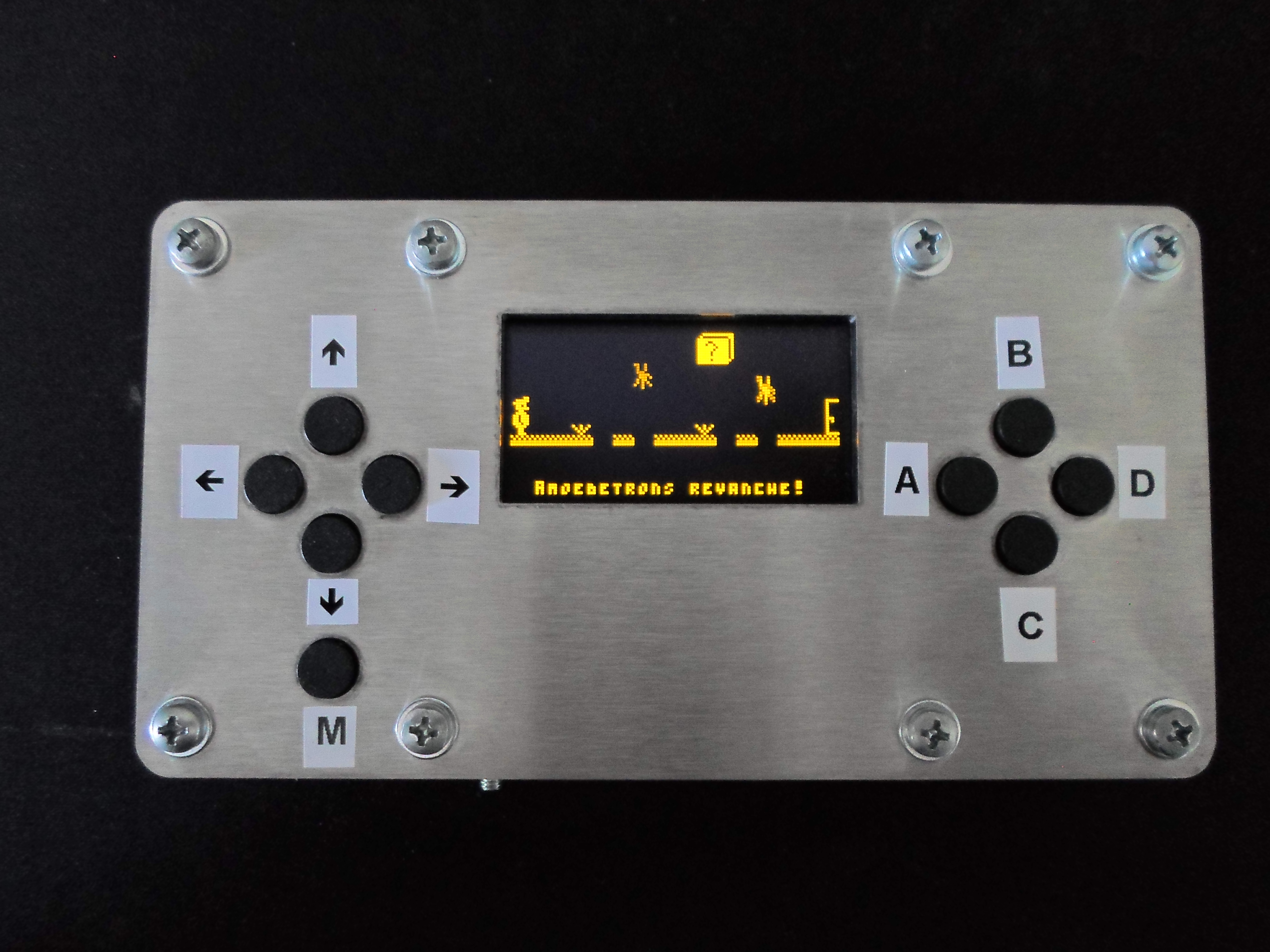
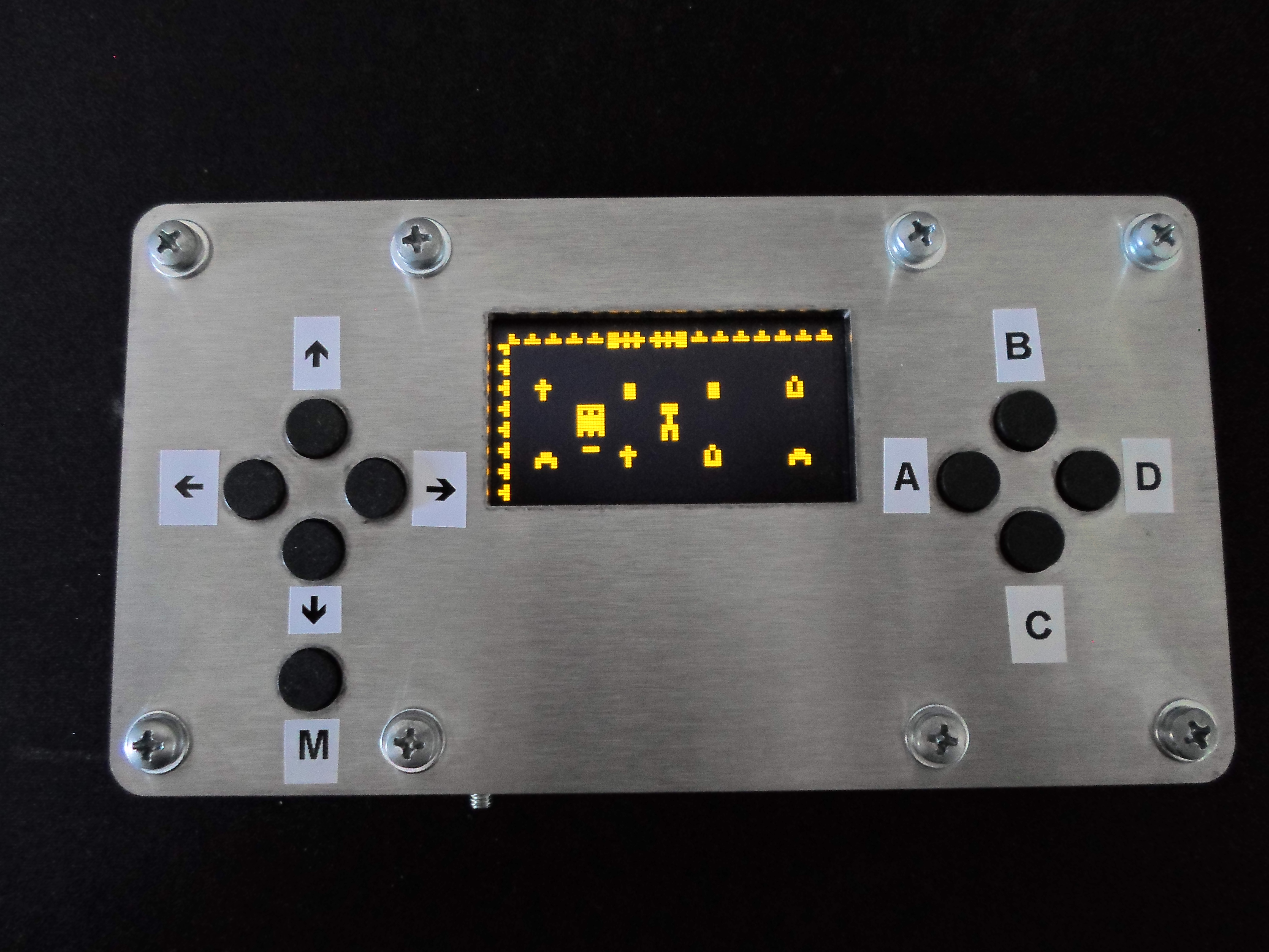
Playing some video games :
3D VIP'r Maze :
 Ant :
 Glitch Ghost :
| Qty | Value | Footprint | References |
|---|---|---|---|
| 13 | 100n | Capacitor_SMD:C_0603_1608Metric_Pad1.08x0.95mm_HandSolder | C2, C4, C9, C10, C11, C12, C13, C14, C15, C16, C17, C18, C19 |
| 9 | 100K | Resistor_SMD:R_0603_1608Metric_Pad0.98x0.95mm_HandSolder | R5, R6, R7, R8, R9, R10, R11, R12, R13 |
| 9 | D6R90_F1_LFS | D6R90_F1_LFS:SW_D6R90_F1_LFS | SW2, SW3, SW4, SW5, SW6, SW7, SW8, SW9, SW10 |
| 7 | 10K | Resistor_SMD:R_0603_1608Metric_Pad0.98x0.95mm_HandSolder | R4, R14, R18, R19, R20, R21, R22 |
| 6 | CASING_HOLE | MountingHole:MountingHole_4.5mm_Pad_Via | H1, H2, H3, H4, H5, H6 |
| 5 | 2.2u | Capacitor_SMD:C_0805_2012Metric_Pad1.18x1.45mm_HandSolder | C1, C3, C5, C6, C20 |
| 2 | 10u | Capacitor_SMD:C_0805_2012Metric_Pad1.18x1.45mm_HandSolder | C21, C22 |
| 2 | 220 | Resistor_SMD:R_0603_1608Metric_Pad0.98x0.95mm_HandSolder | R15, R17 |
| 2 | 4.7u | Capacitor_SMD:C_0805_2012Metric_Pad1.18x1.45mm_HandSolder | C7, C8 |
| 1 | 1286AS-H-2R2M=P2 | Inductors:0806_HandSolder | L1 |
| 1 | 150080SS75000 | LED_SMD:LED_0805_2012Metric_Pad1.15x1.40mm_HandSolder | D1 |
| 1 | 1K | Resistor_SMD:R_0603_1608Metric_Pad0.98x0.95mm_HandSolder | R1 |
| 1 | 22u | Capacitor_SMD:C_1210_3225Metric_Pad1.33x2.70mm_HandSolder | C23 |
| 1 | 560 | Resistor_SMD:R_0603_1608Metric_Pad0.98x0.95mm_HandSolder | R3 |
| 1 | 6.8K | Resistor_SMD:R_0603_1608Metric_Pad0.98x0.95mm_HandSolder | R2 |
| 1 | BATTERY | Connector_PinHeader_2.54mm:PinHeader_1x02_P2.54mm_Horizontal | J3 |
| 1 | CMT-1604-SMT-TR | CMT-1604-SMT-TR:CMT-1604-SMT-TR | BZ1 |
| 1 | DEBUG_UART | Connector_PinHeader_2.54mm:PinHeader_1x03_P2.54mm_Horizontal | J5 |
| 1 | DISPLAY | Connector_PinHeader_2.54mm:PinHeader_1x07_P2.54mm_Horizontal | J2 |
| 1 | DM1B-DSF-PEJ(92) | DM1B-DSF-PEJ(92):DM1B-DSF-PEJ(92) | J1 |
| 1 | JTAG | Connector_PinHeader_2.54mm:PinHeader_1x05_P2.54mm_Horizontal | J4 |
| 1 | OS102011MA1QN1 | Button_Switch_THT:SW_Slide_SPDT_Angled_CK_OS102011MA1Q | SW1 |
| 1 | PIC18F27K42-xSO | Package_SO:SOIC-28W_7.5x17.9mm_P1.27mm | U2 |
| 1 | PMV27UPE | Package_TO_SOT_SMD:SOT-23 | Q1 |
| 1 | TPS613221ADBV | Package_TO_SOT_SMD:SOT-23-5 | U1 |
| 1 | Waveshare_2.42inch_OLED_Module | Waveshare_2.42inch_OLED_Module:2.42inch_OLED_Module | DISP1 |

TheSlowGrowth/TapeLooper
A digital tape looper module for Eurorack or standalone use, built on the Daisy Seed.

LadyRoninEngineer/Si473x
Data Supporting development of Si473x series radios

robotique-udes/Exo_Electric
This repo contains all the information about the PCB and electrical schematics of Biogenius.


lucasnoce/IC-LevelSensor_v2
Water level sensor with NBIoT data transmission

rappet/ferris-badge
Small badge running on a coin cell using a STM32L031G6U with embassy.

It measures 166 × 81 mm and has 2 copper layers, 1.6 mm thick.
72 parts, built around the TPS613221ADBV, DM1B-DSF-PEJ(92), D6R90F1LFS and 1286AS-H-2R2M=P2. The full list of its parts is on this page, with links to each part's symbol and footprint where PCBKit's library has them.
From the RICCIARDI-Adrien/Chip8_Console repository on GitHub, at the commit this page was made from: the board is Hardware/Motherboard/Console.kicad_pcb and its schematic Hardware/Battery_Hatch/Battery_Hatch.kicad_sch. PCBKit opens the board in the browser, with nothing to install.
Its repository publishes it under the MIT licence: you may reuse it on that licence's terms (keep the author's notice, and for a copyleft licence share your changes alike).