
2 layers245.1 × 160 mm
8-Bit CPU 32k
slu4coder/Minimal-64x4-Home-Computer
My DIY TTL home computer with VGA and PS/2 and 4x the processing power of a Commodore C64 or Apple II.
139 parts326
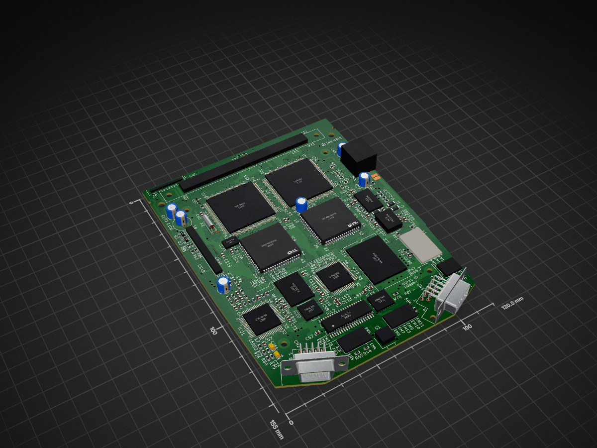
 RGBeter/Sega_CDX_Reproduction5
Reproduction schematics and PCB of the Sega CDX Main board
CDX Repro is an open-source printed circuit board by RGBeter, from the RGBeter/Sega_CDX_Reproduction repository on GitHub, published under the CERN-OHL-S-2.0 licence. It is a 6-layer board of 120.5 × 155 mm with 260 parts on 605 nets, routed with 20,374 tracks and 1,408 vias.
It is built around the 74HC00D. Its parts include 111 capacitors, 78 resistors, 23 ICs, 4 connectors and 3 inductors.
Reproduction schematics and PCB of the Sega CDX Main board


These PCBs are NOT TESTED! I HAVE NOT MADE OR TESTED THEM AND YOU DO SO AT YOUR OWN RISK. They SHOULD work as they were designed through tracing the original PCB, but bugs may appear and should be disclosed in the issues tab if encountered. Building these requires skills in microsoldering, QFP soldering, hot air rework, and Mega Drive troubleshooting. It is highly recommended you start with a set of known working parts from a donor MegaDrive. VA1, VA1.8 and VA3 Model 2 Sega Genesis/MegaDrive can provide all of the necessary custom chips needed for the mega drive portion of this build. Obtaining A CDX or late Funai Sega CD Model 2 is required due to Sega's use of 315-5619.
Support is not officially provided by RGBeter with building or debugging these PCBs.
Sega used a strange 6 layer stackup that caused issues in noise performance with the CDX. This PCB has an updated 6 layer board stackup that should improve noise characteristics while preserving the original trace routing when possible.
"CDX_FAB.zip" Contains gerber files to fabricate your own boards, do note that these do not contain BOM or POS files for PCBA, and you will need to generate them for your specific manufacturer of choice from the KiCad source files.
| Qty | Value | Footprint | References |
|---|---|---|---|
| 34 | 0.1uF | Capacitor_SMD:C_0805_2012Metric | C2, C21, C22, C25, C31, C34, C41, C42, C43, C45, C51, C52, C54, C100, C101, C105 +18 |
| 23 | 4.7K | Resistor_SMD:R_0805_2012Metric | R3, R4, R5, R6, R10, R18, R32, R33, R34, R36, R48, R49, R55, R56, R57, R58 +7 |
| 16 | CDX_EMI | CDX:CDX_EMI | EM1, EM2, EM3, EM4, EM5, EM6, EM7, EM8, EM9, EM10, EM11, EM12, EM13, EM14, EM15, EM16 |
| 14 | 100pF | Capacitor_SMD:C_0805_2012Metric | C3, C5, C44, C53, C62, C63, C64, C66, C67, C68, C73, C112, C113, C118 |
| 12 | 2.2K | Resistor_SMD:R_0805_2012Metric | R11, R12, R13, R15, R16, R17, R19, R37, R50, R59, R61, R81 |
| 10 | 10uF | Capacitor_Tantalum_SMD:CP_EIA-3216-10_Kemet-I | C36, C76, C77, C78, C79, C80, C81, C86, C88, C106 |
| 10 | ? | Resistor_SMD:R_0805_2012Metric | FB1, FB2, FB3, FB4, FB5, FB7, FB8, FB16, FB17, FB18 |
| 9 | ? | Capacitor_SMD:C_0805_2012Metric | C14, C16, C110, C111, C114, C115, C116, C120, C121 |
| 8 | * | Capacitor_SMD:C_0805_2012Metric | C1, C15, C18, C23, C24, C32, C33, C119 |
| 7 | 0 | Resistor_SMD:R_0805_2012Metric | FB6, FB14, J1, J2, J3, J4, R78 |
| 6 | 1.2K | Resistor_SMD:R_0805_2012Metric | R20, R29, R30, R31, R40, R41 |
| 5 | 33pF | Capacitor_SMD:C_0805_2012Metric | C4, C12, C17, C60, C70 |
| 5 | 75R | Resistor_SMD:R_0805_2012Metric | R39, R69, R70, R79, R80 |
| 4 | 330R | Resistor_SMD:R_0805_2012Metric | R44, R45, R46, R47 |
| 4 | 8.2K | Resistor_SMD:R_0805_2012Metric | R22, R23, R24, R25 |
| 4 | 8200pF | Capacitor_SMD:C_0805_2012Metric | C82, C83, C87, C89 |
| 3 | * | Resistor_SMD:R_0805_2012Metric | R14, R83, R85 |
| 3 | 1K | Resistor_SMD:R_0805_2012Metric | R35, R38, R52 |
| 3 | 1uF | Capacitor_Tantalum_SMD:CP_EIA-3216-10_Kemet-I | C26, C35, C40 |
| 3 | 220uF | CDX:Cap_ELEC_2.5mm | C29, C46, C107 |
| 3 | 5.6K | Resistor_SMD:R_0805_2012Metric | R26, R27, R28 |
| 2 | 1000pF | Capacitor_SMD:C_0805_2012Metric | C11, C13 |
| 2 | 100uF | CDX:Cap_ELEC_2.5mm | C27, C90 |
| 2 | 11K | Resistor_SMD:R_0805_2012Metric | R75, R76 |
| 2 | 180pF | Capacitor_SMD:C_0805_2012Metric | C48, C50 |
| 2 | 2.7K | Resistor_SMD:R_0805_2012Metric | R60, R62 |
| 2 | 2200pF | Capacitor_SMD:C_0805_2012Metric | C84, C85 |
| 2 | 22uF | Capacitor_Tantalum_SMD:CP_EIA-3528-12_Kemet-T | C19, C38 |
| 2 | 3.3K | Resistor_SMD:R_0805_2012Metric | R53, R54 |
| 2 | 3300pF | Capacitor_SMD:C_0805_2012Metric | C30, C39 |
| 2 | 4.7uF | Capacitor_Tantalum_SMD:CP_EIA-3216-10_Kemet-I | C9, C10 |
| 2 | 680pF | Capacitor_SMD:C_0805_2012Metric | C91, C92 |
| 2 | MC68000FN | CDX:PLCC-68k | IC1, IC9 |
| 2 | NPN | CDX:SOT_Transistor | Q1, Q2 |
| 2 | WordRAM | CDX:SOJ-40 | IC15, IC16 |
| 1 | 0 | Capacitor_SMD:C_0805_2012Metric | C122 |
| 1 | 0 | Inductor_SMD:L_1806_4516Metric_Pad1.45x1.90mm_HandSolder | L3 |
| 1 | 0.01uF | Capacitor_SMD:C_0805_2012Metric | C49 |
| 1 | 1.6K | Resistor_SMD:R_0805_2012Metric | R51 |
| 1 | 100uH | Inductor_SMD:L_1806_4516Metric_Pad1.45x1.90mm_HandSolder | L1 |
| 1 | 10K | Resistor_SMD:R_0805_2012Metric | R84 |
| 1 | 12uH | Inductor_SMD:L_1806_4516Metric_Pad1.45x1.90mm_HandSolder | L2 |
| 1 | 150R | Resistor_SMD:R_0805_2012Metric | R1 |
| 1 | 18pF | Capacitor_SMD:C_0805_2012Metric | C47 |
| 1 | 1k | Resistor_SMD:R_0805_2012Metric | R21 |
| 1 | 2.2uF | Capacitor_Tantalum_SMD:CP_EIA-3216-10_Kemet-I | C20 |
| 1 | 2.4K | Resistor_SMD:R_0805_2012Metric | R72 |
| 1 | 220R | Resistor_SMD:R_0805_2012Metric | R2 |
| 1 | 220uF | CDX:Cap_ELEC_DUAL | C108 |
| 1 | 315-5476 | CDX:315-5476_QFP-80_14x20_Pitch0.8mm | IC17 |
| 1 | 315-5619 | CDX:Sanyo_QFP-64_14x14_Pitch0.8mm | IC21 |
| 1 | 315-5632 | CDX:QFP-208_28x28_Pitch0.5mm | IC14 |
| 1 | 315-5684 | CDX:315-5684 | IC7 |
| 1 | 424270 | CDX:SOJ-40 | IC12 |
| 1 | 47K | Resistor_SMD:R_0805_2012Metric | R82 |
| 1 | 50MHz | CDX:Crystal_Horizontal | X2 |
| 1 | 53.693175MHz/53.203424MHz | CDX:OSC_DUAL | X1 |
| 1 | 560R | Resistor_SMD:R_0805_2012Metric | R43 |
| 1 | 56R | Resistor_SMD:R_0805_2012Metric | R71 |
| 1 | 74HC00 | CDX:SOIC-14 | IC22 |
| 1 | AV_OUT | CDX:MiniDIN_9 | JK1 |
| 1 | BOOT ROM | CDX:SOIC-40_BIOS | IC11 |
| 1 | BRAM | CDX:SOIC-28 | IC10 |
| 1 | CD_CONNECTOR | CDX:CD_CON | CN4 |
| 1 | FC1004 | CDX:QFP-208_28x28_Pitch0.5mm | IC5 |
| 1 | KM78128 | CDX:SOIC-28 | IC20 |
| 1 | LC33864 | CDX:SOIC-32 | IC18 |
| 1 | LC89513 | CDX:Sanyo_QFP-64_14x14_Pitch0.8mm | IC19 |
| 1 | MB3514 | CDX:SOIC-24 | IC8 |
| 1 | MB3790 | CDX:SOIC-16 | IC13 |
| 1 | ML2016 | CDX:ML2016 | Z1 |
| 1 | NJU6332 | CDX:SOIC-8 | IC23 |
| 1 | PORT_A | CDX:DSUB-9 | CN2 |
| 1 | PORT_B | CDX:DSUB-9 | CN3 |
| 1 | PWR_CONN | CDX:POWER_CN | CN5 |
| 1 | PWR_SW | CDX:Power_SW | S1 |
| 1 | VRAM | CDX:SOJ-40 | IC6 |
| 1 | WORK RAM | CDX:SOIC-40 | IC2 |
| 1 | Z80_QFP | CDX:Z80_QFP-44_10.35x10.35_Pitch0.8mm | IC3 |
| 1 | ZRAM | CDX:SOIC-28 | IC4 |
The 259 most common of 260 parts.
slu4coder/Minimal-64x4-Home-Computer
My DIY TTL home computer with VGA and PS/2 and 4x the processing power of a Commodore C64 or Apple II.

slu4coder/Minimal-UART-Computer-1-2
Legacy: Version 1 and 2 of my TTL-only CPU featuring UART I/O, an expansion port, 512KB SSD at up to 10MHz clock speed


Kris-Sekula/EPROM-EMU-NG
EPROM Emulator Project with Arduino


tebl/BE6502-Build-a-65c02-computer
A PCB being made while watching Ben Eaters "Build a 6502 computer" video series. Includes the computer itself, a standalone slow clock and an Arduino Mega shield for the bus monitor sketch..

slu4coder/Minimal-64-Home-Computer
Legacy: Full TTL-only home computer with VGA and PS/2 and twice the processing power of a Commodore 64

It measures 120.5 × 155 mm and has 6 copper layers, 1.6 mm thick.
260 parts, built around the 74HC00D. The full list of its parts is on this page, with links to each part's symbol and footprint where PCBKit's library has them.
From the RGBeter/Sega_CDX_Reproduction repository on GitHub, at the commit this page was made from: the board is CDX_Repro.kicad_pcb and its schematic AV.kicad_sch. PCBKit opens the board in the browser, with nothing to install.
Its repository publishes it under the CERN-OHL-S-2.0 licence: you may reuse it on that licence's terms (keep the author's notice, and for a copyleft licence share your changes alike).