

2 layers70 × 102 mm
RayCouplers
RFStateSide/RayCouplers
Open-hardware 200 W and 2 kW RF directional coupler designs by RF StateSide LLC
54 partsCERN-OHL-P-2.0
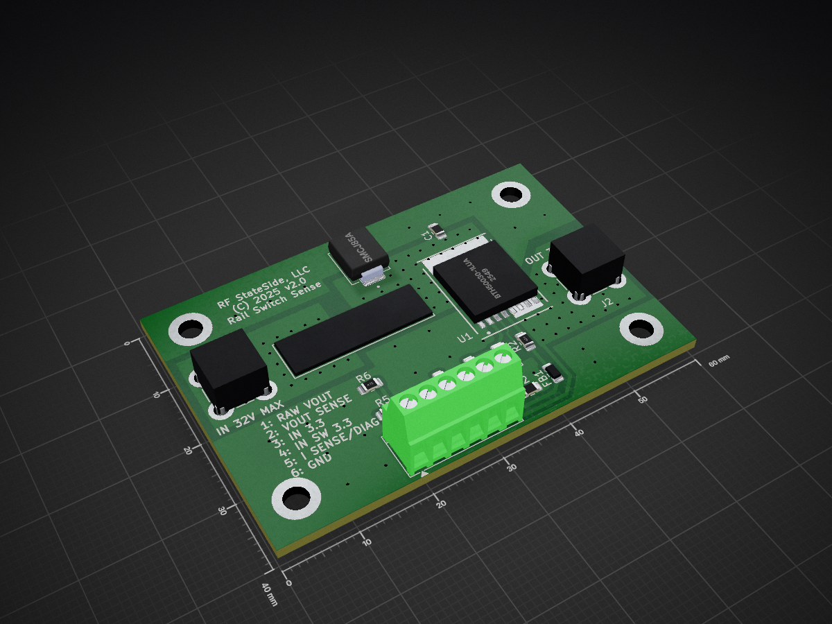
 RFStateSide/RayRailSwSense
High-side DC rail switching and current-sensing hardware for RF amplifier applications. Public Engineering Reference — AS-IS.
RayRailSwSense is an open-source printed circuit board by RFStateSide, from the RFStateSide/RayRailSwSense repository on GitHub, published under the CERN-OHL-P-2.0 licence. It is a 2-layer board of 60 × 40 mm with 19 parts on 12 nets, routed with 87 tracks and 98 vias.
It is built around the BTH500301LUAAUMA1, RMCF0805FT4K70 and CL21B103KDCNNNC, with the CL21B104KBCNFNC, RMCF1206FT2K00 and RMCF0805FT82K0 among its other parts. Its parts include 6 resistors, 3 connectors, 2 capacitors, 1 IC and 1 diode. It belongs with the audio and music and radio and wireless boards of this library.


RayRailSwSense is RF StateSide LLC's high-side DC rail switch with current and switched-output voltage sensing for amplifier and instrumentation development.
Public Engineering Reference — AS-IS. Editable KiCad sources, a population BOM and manufacturing files support study, independent construction, modification and continued development.
PCBWay manufactured the redesigned BTH board. We hand-populated it using a reflow oven and successfully tested it with RayPowerMeter and RaySspaController. The tested assembly used BTH500301LUAAUMA1, R4 = 2 kΩ, a Murata BLM31PG121SN1L ferrite bead and a 25 A, 32 VDC automotive-type fuse. The fuse rating is not evidence of a measured 25 A continuous test.
BTH500151LUAAUMA1 is an alternative device selection, not a separately verified assembly or a higher-rated board variant. See assembly and history.
The supplied P2-prep-01 files reconcile the tested population and source metadata while retaining the original copper, drilling, placement and routing. Revised labeling and regenerated outputs distinguish this package from the original fabrication submission. This prepared revision has not itself been fabricated or physically tested.
The installed 178.6165.0002 fuse holder has a 32 VDC maximum, 30 A maximum current and a manufacturer's 22.5 A continuous component figure. These are component limits, not a complete-board operating specification. No guaranteed continuous board current is established. Do not operate above the installed holder's limits. See known limitations.
The sense connector is not directly interchangeable with the saved RaySspaController connector revisions. Pin 1 carries raw switched rail voltage. Use the integration guide, not a straight-through cable assumption. Current-sense fault output is not guaranteed to remain within 3.3 V.
Open the KiCad 9 project. Required symbols and footprints are included in project-local libraries; optional 3D models are omitted. View schematic · View PCB front.
Use the BOM and manufacturing instructions together. FB1's owner-confirmed 1206 component is represented on the retained 0805 lands: this is an explicit historical fit limitation, not a standard land-pattern recommendation.
| Location | Contents |
|---|---|
| hardware/ | Portable editable project and local libraries |
| bom/ | Tested-population procurement reference and assembly notes |
| manufacturing/ | Identified Gerber, drill, placement and BOM package |
| docs/ | Integration, history, limitations, provenance and verification |
| tools/ | Generation and integrity/engineering verification utilities |
| PUBLIC_RELEASE_AUDIT.md | Attributed technical validation record |
Original historical designs, supplier records and fabrication archives are retained separately. No parent firmware or development-repository history is included.
KiCad was used for schematic capture and PCB design. Python utilities support source verification and manufacturing-package integrity checks. Git and GitHub are the intended version-control and distribution tools.
ChatGPT by OpenAI and OpenAI Codex assisted with engineering review, documentation, source organization, validation and preparation of the open-hardware reference. RF StateSide LLC performed the original hardware design, assembly and historical integration testing.
Copyright RF StateSide LLC. Original contributions are provided under CERN-OHL-P v2.0, SPDX CERN-OHL-P-2.0. The unmodified LICENSE is authoritative; retain NOTICE and applicable library notices. See licensing and provenance.
RF StateSide created the project-specific symbols and custom footprints. KiCad contributors supplied the stock and upstream-derived definitions. No certification, guaranteed performance, future development or technical support is promised.
| Qty | Value | Footprint | References |
|---|---|---|---|
| 4 | 4.7K | RayRailSwSense:Resistor_SMD_R_0805_2012Metric_Pad1.20x1.40mm_HandSolder | R1, R2, R3, R6 |
| 4 | MountingHole_3.2mm_M3_ISO7380_Pad_TopBottom_Gnd | RayRailSwSense:MyFootprints_MountingHole_3.2mm_M3_ISO7380_Pad_TopBottom_Gnd | H1, H2, H3, H4 |
| 2 | 74650074R | RayRailSwSense:MyFootprints_CONN_74650074R_WRE | J1, J2 |
| 1 | .01 µF | RayRailSwSense:Capacitor_SMD_C_0805_2012Metric_Pad1.18x1.45mm_HandSolder | C2 |
| 1 | .1 µF | RayRailSwSense:Capacitor_SMD_C_0805_2012Metric_Pad1.18x1.45mm_HandSolder | C1 |
| 1 | 178.6165.0002 | RayRailSwSense:MyFootprints_FUSE_178.6165.0002_LTF | F1 |
| 1 | 2k | RayRailSwSense:LED_SMD_LED_1206_3216Metric_Pad1.42x1.75mm_HandSolder | R4 |
| 1 | 82K | RayRailSwSense:Resistor_SMD_R_0805_2012Metric_Pad1.20x1.40mm_HandSolder | R5 |
| 1 | BLM31PG121SN1L | RayRailSwSense:Inductor_SMD_L_0805_2012Metric_Pad1.15x1.40mm_HandSolder | FB1 |
| 1 | BTH50030-1LUA | RayRailSwSense:MyFootprints_IFX-PG-HSOF-5-6-7-8 | U1 |
| 1 | SMCJ85A | RayRailSwSense:MyFootprints_DIOM7959X262N | D1 |
| 1 | Screw_Terminal_01x06 | RayRailSwSense:TerminalBlock_TE-Connectivity_TerminalBlock_TE_282834-6_1x06_P2.54mm_Horizontal | J3 |
RFStateSide/RayCouplers
Open-hardware 200 W and 2 kW RF directional coupler designs by RF StateSide LLC


hackclub/OnBoard
💡 Join 1,000 teenagers and make your first PCB with a $100 grant!

polpo/picogus
Emulation of ISA sound cards and CD-ROM on Raspberry Pi Pico (GUS, SB/Adlib, MPU-401, Tandy, CMS, Panasonic CD-ROM) with USB mouse/joystick support


nkitanov/iaq_board
IAQ Board is a DIY (Do-It-Yourself) device for measuring internal air quality
It measures 60 × 40 mm and has 2 copper layers, 1.6 mm thick.
19 parts, built around the BTH500301LUAAUMA1, RMCF0805FT4K70, CL21B103KDCNNNC and CL21B104KBCNFNC. The full list of its parts is on this page, with links to each part's symbol and footprint where PCBKit's library has them.
From the RFStateSide/RayRailSwSense repository on GitHub, at the commit this page was made from: the board is hardware/RayRailSwSense.kicad_pcb and its schematic hardware/RayRailSwSense.kicad_sch. PCBKit opens the board in the browser, with nothing to install.
Its repository publishes it under the CERN-OHL-P-2.0 licence: you may reuse it on that licence's terms (keep the author's notice, and for a copyleft licence share your changes alike).