2 layers30 × 61.3 mm

 Qeteshpony/USB-C-Cable-Tester1
Small passive device for determining the capabilities of a USB-C Cable
USB Cable Tester is an open-source printed circuit board by Qeteshpony, from the Qeteshpony/USB-C-Cable-Tester repository on GitHub, published under the BSD-2-Clause licence. It is a 2-layer board of 50 × 64 mm with 45 parts on 57 nets, routed with 194 tracks and 32 vias.
It is built around the USB3.0. Its parts include 18 resistors, 16 diodes and 3 connectors.

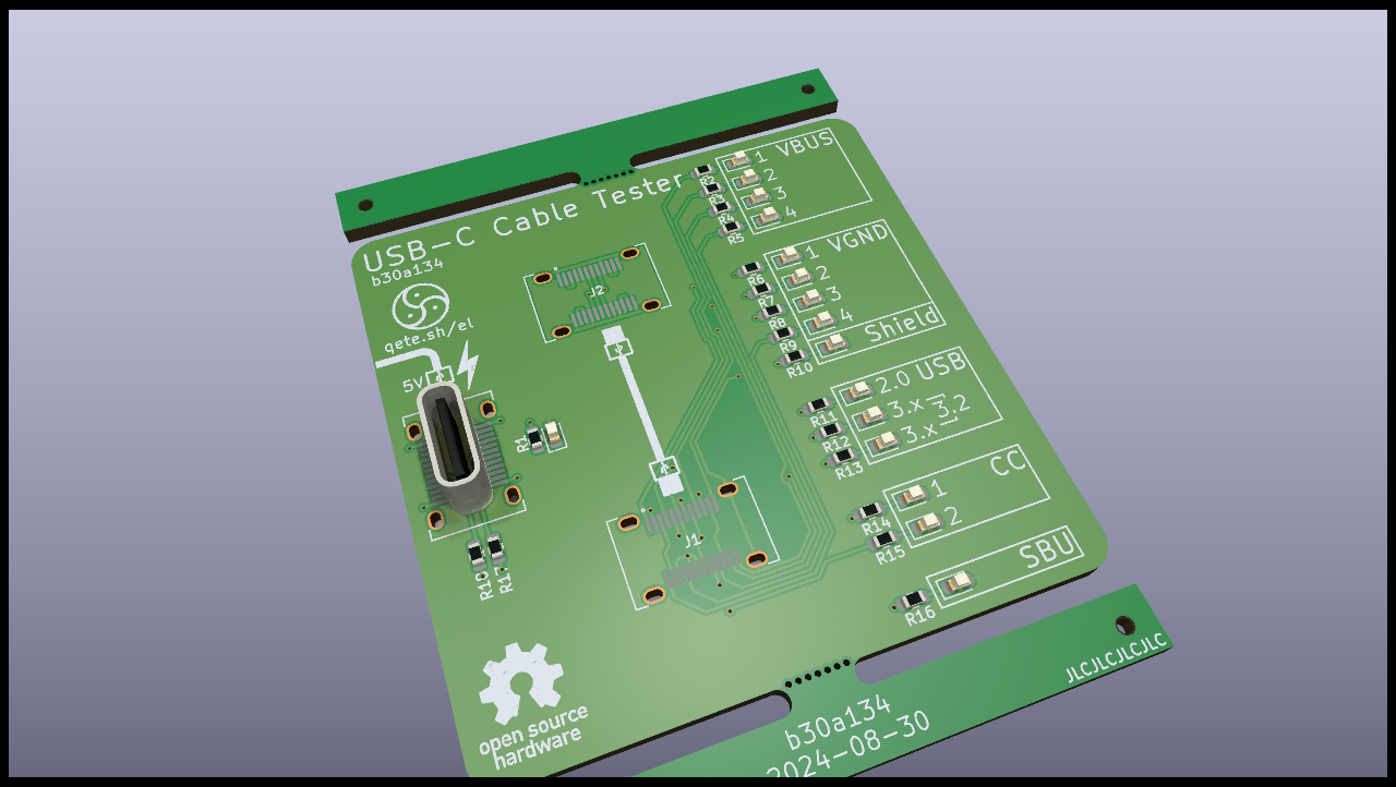
Small passive device for determining the capabilities of a USB-C Cable
This helps when you have a USB-C cable and don't know which USB-Version and other features it supports.
The tester can of course not check for any active circuitry in the cable and might not work at all with active cables but in most cases it should give you a good overview.
| LED | Meaning |
|---|---|
| VBUS 1-4 | One LED for each VBUS connection in the cable. Can give a hint on power capabilities |
| VGND 1-4 | One LED for each Ground connection |
| Shield | Shows if the shielding is connected on both ends |
| USB 2.0 | Lights up when the USB2 differential pair is connected |
| USB 3.x | One LED for each set of TX/RX pairs in the cable. If only one is lit, USB3.2 will not work |
| CC | One of these must be connected, the other should not be. A dim LED can be a hint for an active cable |
| SBU | SideBand Use (See USB Type-C Spec R2.0, chapter 4.3) - Used for alternate modes like audio and video connections |
The PCB is designed with production by JLCPCB in mind and all parts but the USB-Connectors are from their basic parts library. I strongly suggest getting these assembled since soldering the USB connectors by hand is not easy.
| Qty | Value | Footprint | References |
|---|---|---|---|
| 16 | 1k5 | Resistor_SMD:R_0603_1608Metric | R1, R2, R3, R4, R5, R6, R7, R8, R9, R10, R11, R12, R13, R14, R15, R16 |
| 2 | 5k1 | Resistor_SMD:R_0603_1608Metric | R17, R18 |
| 2 | VAL** | Panelization:mouse-bite-2x5mm-slot-onesided-v2 | mouse-bite-2mm-slot, mouse-bite-2mm-slot |
| 1 | CC1 | LED_SMD:LED_0603_1608Metric | D14 |
| 1 | CC2 | LED_SMD:LED_0603_1608Metric | D15 |
| 1 | GND1 | LED_SMD:LED_0603_1608Metric | D6 |
| 1 | GND2 | LED_SMD:LED_0603_1608Metric | D7 |
| 1 | GND3 | LED_SMD:LED_0603_1608Metric | D8 |
| 1 | GND4 | LED_SMD:LED_0603_1608Metric | D9 |
| 1 | LOGO | My_Footprints:CutieMark5mmInverted | G*** |
| 1 | PWR | LED_SMD:LED_0603_1608Metric | D1 |
| 1 | SBU | LED_SMD:LED_0603_1608Metric | D16 |
| 1 | Shield | LED_SMD:LED_0603_1608Metric | D10 |
| 1 | USB2.0 | LED_SMD:LED_0603_1608Metric | D11 |
| 1 | USB3.0 | LED_SMD:LED_0603_1608Metric | D12 |
| 1 | USB3.2 | LED_SMD:LED_0603_1608Metric | D13 |
| 1 | USB_C_IN | My_Footprints:USB_C_Receptacle_GT-USB-7028C | J1 |
| 1 | USB_C_OUT | My_Footprints:USB_C_Receptacle_GT-USB-7028C | J2 |
| 1 | USB_C_Power | My_Footprints:USB_C_Receptacle_GT-USB-7028C | J3 |
| 1 | VBUS1 | LED_SMD:LED_0603_1608Metric | D2 |
| 1 | VBUS2 | LED_SMD:LED_0603_1608Metric | D3 |
| 1 | VBUS3 | LED_SMD:LED_0603_1608Metric | D4 |
| 1 | VBUS4 | LED_SMD:LED_0603_1608Metric | D5 |
The 40 most common of 45 parts.

imchipwood/dumbpad
Simple 4x4 numpad with rotary encoder. Powered by QMK via ATmega32u4 Pro Micro


makeo/PicoLoader
A cheap and easy to install modchip for the Nintendo GameCube!


peterkrull/quad
Firmware, hardware and documentation for my autonomous quad copter project

tebl/RC6502-Apple-1-Replica
An expandable SBC-version of the Apple 1 computer, easy to get started with and lot of cool stuff that can be added to it!

It measures 50 × 64 mm and has 2 copper layers, 1.6 mm thick.
45 parts, built around the USB3.0. The full list of its parts is on this page, with links to each part's symbol and footprint where PCBKit's library has them.
From the Qeteshpony/USB-C-Cable-Tester repository on GitHub, at the commit this page was made from: the board is pcb/USB-Cable-Tester.kicad_pcb and its schematic pcb/USB-Cable-Tester.kicad_sch. PCBKit opens the board in the browser, with nothing to install.
Its repository publishes it under the BSD-2-Clause licence: you may reuse it on that licence's terms (keep the author's notice, and for a copyleft licence share your changes alike).