2 layers50 × 35 mm

 Qeteshpony/BinaryVoltageIndicator1
5V power supply monitor
BinaryVoltageIndicator is an open-source printed circuit board by Qeteshpony, from the Qeteshpony/BinaryVoltageIndicator repository on GitHub, published under the BSD-2-Clause licence. It is a 2-layer board of 20 × 10 mm with 17 parts on 9 nets, routed with 36 tracks and 6 vias.
Its parts include 5 resistors, 2 diodes, 1 capacitor, 1 IC and 1 transistor. It belongs with the power and sensors and measurement boards of this library.

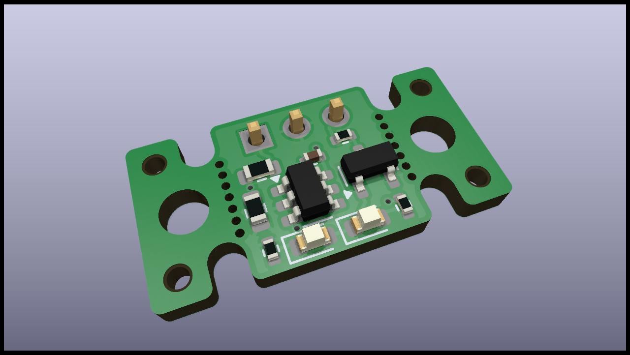
A small board that can be attached to a 5V power supply to show if the voltage is above or below 5.0V with a maximum tolerance of about 2% (±0.1V) when 1% resistors are used.
The board can also be directly plugged onto a Raspberry Pi GPIO header to have a quick visual aid about the power supply status. The third pin is an open collector output that pulls down when the voltage is above 5.0V. When plugged onto the GPIO header this gets connected to GPIO14.
Connections when directly plugged in:
| Board | GPIO Header |
|---|---|
| VCC | 4 (5V) |
| GND | 6 (GND) |
| VOK | 8 (GPIO14) |
When using a cable, VOK can of course be connected to any GPIO Pin or not be used at all.
The "wings" with the screw holes can be used to mount the board in a case or broken off if they are not needed.
| Qty | Value | Footprint | References |
|---|---|---|---|
| 3 | 680R | Resistor_SMD:R_0402_1005Metric | R3, R4, R5 |
| 2 | VAL** | Panelization:mouse-bite-2x5mm-slot-onesided-v2 | mouse-bite-2mm-slot, mouse-bite-2mm-slot |
| 1 | 100n | Capacitor_SMD:C_0402_1005Metric | C1 |
| 1 | 12k | Resistor_SMD:R_0603_1608Metric | R2 |
| 1 | 13k | Resistor_SMD:R_0603_1608Metric | R1 |
| 1 | 2N7002 | Package_TO_SOT_SMD:SOT-23 | Q1 |
| 1 | Conn | Connector_PinHeader_2.54mm:PinHeader_1x03_P2.54mm_Vertical | J1 |
| 1 | MCP65R41-2402 | Package_TO_SOT_SMD:SOT-23-6 | U1 |
| 1 | Power Low | LED_SMD:LED_0603_1608Metric | D1 |
| 1 | Power OK | LED_SMD:LED_0603_1608Metric | D2 |
The 13 most common of 17 parts.


hoglet67/RGBtoHDMI
Bare-metal Raspberry Pi project that provides pixel-perfect sampling of Retro Computer RGB/YUV video and conversion to HDMI


hackclub/OnBoard
💡 Join 1,000 teenagers and make your first PCB with a $100 grant!

DDeGonge/OS-ARM
This arm is not industrial and it will not be fast, but that is not my goal. But it will hopefully be a very nice looking arm fully capable of 6dof motion, cheap enough to keep it accessable but capable enough to…


It measures 20 × 10 mm and has 2 copper layers, 1.6 mm thick.
17 parts. The full list of its parts is on this page, with links to each part's symbol and footprint where PCBKit's library has them.
From the Qeteshpony/BinaryVoltageIndicator repository on GitHub, at the commit this page was made from: the board is pcb/BinaryVoltageIndicator.kicad_pcb and its schematic pcb/BinaryVoltageIndicator.kicad_sch. PCBKit opens the board in the browser, with nothing to install.
Its repository publishes it under the BSD-2-Clause licence: you may reuse it on that licence's terms (keep the author's notice, and for a copyleft licence share your changes alike).