2 layers43.9 × 27.7 mm
 Pyae2014K/Pyae-s-Alarm-Clock
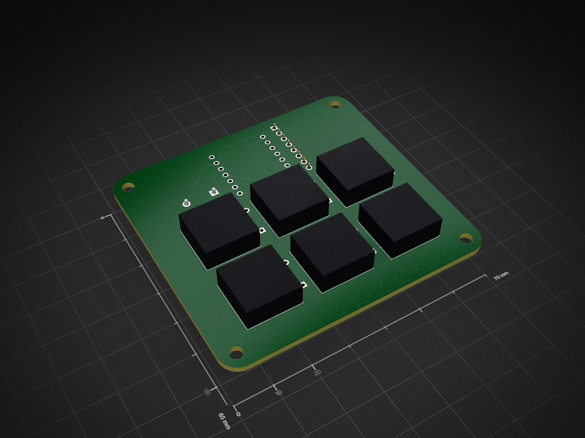
My alarm clock is an alarm clock with 6 keys, a TFT screen, and a buzzer.
Pyae s Alarm Clock is an open-source printed circuit board by Pyae2014K, from the Pyae2014K/Pyae-s-Alarm-Clock repository on GitHub. It is a 2-layer board of 70 × 65 mm with 19 parts on 21 nets, routed with 54 tracks and 0 vias.
Its parts include 6 diodes, 6 switches, 1 IC and 1 connector. It belongs with the lEDs and displays boards and the ESP32 and RISC-V boards of this library.
My alarm clock is an alarm clock with 6 keys, a TFT screen, and a buzzer.
It serves as an alarm clock that I can use every day to wake up on time for school.
Everything fits together using 8 M3 Bolts and heatset inserts.
It has 2 different pieces, the Case and the Plate.
The model was made in Shapr 3D
##PCB My PCB was made using KiCad Schematic
PCB
I used the footprints that were shown in the guide.
This alarm clock uses Arduino IDE It does alarm clock things.
Here is everything you will need to make this alarm clock
6x Charry MX Switches 6x DSA Keycaps 8x M3x5x4 Heatset inserts 8x M3x16mm SHCS Bolts 6x 1N4148 DO-35 Diodes. 1x 2.25in TFT Screen 1x XIAO ESP32C3 1x Case (2 printed parts)
| Qty | Value | Footprint | References |
|---|---|---|---|
| 6 | ~ | ScottoKeebs_MX:MX_PCB_1.00u | S1, S2, S3, S4, S5, S6 |
| 6 | ~ | ScottoKeebs_Components:Diode_DO-35 | D1, D2, D3, D4, D5, D6 |
| 4 | MountingHole | MountingHole:MountingHole_3.2mm_M3 | H1, H2, H3, H4 |
| 1 | Buzzer | Buzzer_Beeper:Buzzer_12x9.5RM7.6 | BZ1 |
| 1 | Conn_01x08_Pin | Connector_PinSocket_2.54mm:PinSocket_1x08_P2.54mm_Vertical | J1 |
| 1 | XIAO-ESP32-C3-SMD | Seeed_Studio_XIAO_Series:XIAO-ESP32-C3-DIP | U1 |

hackclub/OnBoard
💡 Join 1,000 teenagers and make your first PCB with a $100 grant!

polpo/picogus
Emulation of ISA sound cards and CD-ROM on Raspberry Pi Pico (GUS, SB/Adlib, MPU-401, Tandy, CMS, Panasonic CD-ROM) with USB mouse/joystick support


nkitanov/iaq_board
IAQ Board is a DIY (Do-It-Yourself) device for measuring internal air quality


Ardumower/ardumower
Develop an open source robotic lawn mower (HW+SW reference platform)

zmaker/arduino_cookbook
gli sketch del nuovo progetto Arduino Cookbook e dei video di YouTube
It measures 70 × 65 mm and has 2 copper layers, 1.6 mm thick.
19 parts. The full list of its parts is on this page, with links to each part's symbol and footprint where PCBKit's library has them.
From the Pyae2014K/Pyae-s-Alarm-Clock repository on GitHub, at the commit this page was made from: the board is PCB/Pyae's Alarm Clock.kicad_pcb and its schematic PCB/Pyae's Alarm Clock.kicad_sch. PCBKit opens the board in the browser, with nothing to install.
Its repository states no licence, so its author keeps all rights: ask Pyae2014K before reusing the design.